非圆齿轮是在圆柱齿轮的基础上衍生而来的,可实现变传动比传动。鉴于其特殊的传动形式,非圆齿轮主要应用于低速、大扭矩场合,例如:包装机、插秧机、抽油机和液压马达等[1]。Burrows等[2]在飞虱的幼体后腿近端关节处发现一种非圆齿轮机构,通过此机构使飞虱达到快速跳跃的目的,可发现非圆齿轮具有其优越性。由非圆齿轮副组合形成的非圆齿轮行星轮系,可实现复杂的特殊运动,例如动态换向、变速传动等,被广泛应用于农业、航天、医疗等领域[3]。
非圆齿轮行星轮系的动力学特性决定了其应用特性,而时变啮合角、节曲线以及齿廓的差异性导致非圆齿轮的动力学模型比圆齿轮更为复杂。文献[3-5]对齿轮系统的振动与混沌特性进行的探索,为行星轮系的动力学研究提供了理论依据。在此基础上国内外学者开展了对行星轮系动力学特性的研究,魏静等[6]以NGW型行星轮系为研究对象,给出了其扭转振动模式和全振动模式等典型振型,但忽略了中心构件的轴间弹性位移。王鑫等[7]建立了含断齿和磨损故障的行星轮系非线性动力学方程,为考虑复杂因素下的系统动力学分析提供了理论依据。Zghal等[8]提出了一种新的行星轮系动力学建模方法,提高了行星轮系动力学建模的效率。Huang等[9]对含齿面摩擦的齿轮系统动态性能进行了研究,优化了含复杂因素系统的动力学建模过程。文献[10-11]在综合考虑时变啮合刚度、齿侧间隙与综合啮合误差等非线性因素的基础上,建立了行星轮系的非线性动力学模型,并对齿轮传动系统的振动特性进行分析,为齿轮传动系统减振降噪提供了理论依据。
在上述对圆柱齿轮动力学研究的基础上,学者们开展了对非圆齿轮动力学的初步探索。刘大伟等[12]在同时考虑轮齿弹性变形和齿侧间隙等因素影响下,建立了周期负载的两级非圆齿轮的拍击振动模型,为非圆齿轮行星轮系扭转模型建立提供了理论依据。董长斌等[13]建立了椭圆齿轮非线性动力学模型,研究了激励频率等参数对系统动态特性的影响。Lin等[14]对偏心的非圆面齿轮进行了动力学特性分析。温芳等[15]对含齿间摩擦的椭圆齿轮进行非线性动力学分析,为时变摩擦激励下非圆齿轮行星轮系动力学模型建立提供一定的理论指导。
上述研究仅对非圆齿轮副系统的动力学特性进行了研究,而对非圆齿轮行星轮系传动系统动力学特性的研究尚未见文献刊载。非圆齿轮行星轮系传动是一种复杂的耦合转子系统,为消除其服役过程中的非线性振动,对其进行非线性动力学特性分析显得尤为重要。本文在综合考虑齿面摩擦、时变啮合刚度、齿侧间隙、黏弹性阻尼、静态传递误差的基础上,通过引入相对位移坐标消除方程耦合,建立非圆齿轮行星轮系非线性动力学模型,并对其非线性特性进行研究,以期为非圆齿轮传动系统的减振、动力学行为预测提供理论依据。
1 非圆齿轮成形原理 1.1 啮合原理非圆齿轮根据需求导向,通过选择不同基曲线作为其节曲线。图 1为非圆齿轮节曲线,其中:a为中心距,A为长半轴长,c为半焦距,θ1, θ2分别为主、从动轮转角。

|
图 1 非圆齿轮节曲线 Fig. 1 Non-circular gear pitch curve |
根据弧长公式与非圆齿轮的节曲线方程的关系得到以下方程组:
| $ \begin{gathered} \int_0^{2 \mathtt{π}} \sqrt{\left(\frac{A\left(1-e^2\right)}{1-e \cos (N \theta)}\right)^2+\left(\mathrm{d}\left(\frac{A B\left(1-e^2\right)}{1-e \cos (N \theta)}\right) / \mathrm{d} \theta\right)^2} \mathrm{d} \theta- \\ \mathtt{π} m z=0 \end{gathered} $ | (1) |
式中:e为椭圆的偏心率,N为椭圆齿轮的阶数,θ为主动轮转角,z为齿数,m为模数。由式(1)可确定非圆齿轮齿数z、模数m,进而获得非圆齿轮的基本参数。
1.2 齿面方程建立基于非圆齿轮啮合原理及基本参数,通过模拟展成法加工的方式获取齿面方程,其中,产形齿轮的齿面方程为[16]
| $ y_{\mathrm{r}}(u)= \begin{cases}h_{\mathrm{f}} & , \frac{3 \mathtt{π} m}{4}+h_{\mathrm{f}} \tan \alpha_2 \leqslant u \leqslant \mathtt{π} m \\ -\frac{1}{\tan \alpha_1} \boldsymbol\cdot\left(u-\frac{\mathtt{π} m}{4}\right) & , \frac{\mathtt{π} m}{4}-h_{\mathrm{f}} \tan \alpha_1 \leqslant u \leqslant \frac{\mathtt{π} m}{4}+h_{\mathrm{f}} \tan \alpha_1 \\ -h_{\mathrm{a}} & , \frac{\mathtt{π} m}{4}+h_{\mathrm{f}} \tan \alpha_1 \leqslant u \leqslant \frac{3 \mathtt{π} m}{4}-h_{\mathrm{f}} \tan \alpha_1 \\ \frac{1}{\tan \alpha_2} \boldsymbol\cdot\left(u-\frac{3 \mathtt{π} m}{4}\right) & , \frac{3 \mathtt{π} m}{4}-h_{\mathrm{f}} \tan \alpha_2 \leqslant u \leqslant \frac{3 \mathtt{π} m}{4}+h_{\mathrm{f}} \tan \alpha_2 \\ h_{\mathrm{f}} & , 0 \leqslant u \leqslant \frac{\mathtt{π} m}{4}-h_{\mathrm{f}} \tan \alpha_1\end{cases} $ | (2) |
其矢量表达式为
| $ \boldsymbol{R}_{\mathrm{r}}(u, v)=\left[\begin{array}{lll} u & y_{\mathrm{r}}(u) & v \end{array}\right]^{\mathrm{T}} $ | (3) |
齿条刀具齿面法向量为
| $ \boldsymbol{n}_{\mathrm{rr}}(u, v)=\frac{\partial \boldsymbol{R}_{\mathrm{r}}(u, v)}{\partial u} \times \frac{\partial \boldsymbol{R}_r(u, v)}{\partial v} $ | (4) |
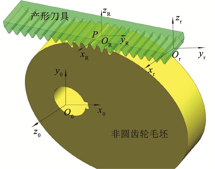
图 2为产形运动关系,建立非圆齿轮的固定坐标系S0(O0-x0y0z0)、非圆齿轮节曲线与工具齿条接触点坐标系SR(OR-xRyRzR)以及固定在工具齿条上的插刀坐标系Sr(Or-xryrzr)。通过S0-SR-Sr坐标系间的坐标变换获取非圆齿轮的齿廓坐标。
|
图 2 产形运动关系 Fig. 2 Production-based motion relationship |
坐标系S0、SR之间的坐标变换为
| $ \boldsymbol{M}_{0 \mathrm{R}}(\varphi)=\left[\begin{array}{cccc} \boldsymbol{n}_{\mathrm{r} 0} & \boldsymbol{t}_{\mathrm{r} 0} & \boldsymbol{q}_{\mathrm{r} 0} & 0 \\ \boldsymbol{n}_{\mathrm{r} 1} & \boldsymbol{t}_{\mathrm{r} 1} & \boldsymbol{q}_{\mathrm{r} 1} & 0 \\ \boldsymbol{n}_{\mathrm{r} 2} & \boldsymbol{t}_{\mathrm{r} 2} & \boldsymbol{q}_{\mathrm{r} 2} & 0 \\ 0 & 0 & 0 & 1 \end{array}\right] $ | (5) |
式中:φ为非圆齿轮转角,nr、tr、qr为3个坐标轴的单位矢量。
坐标系SR和Sr之间的坐标变换为
| $ \boldsymbol{M}_{\mathrm{Rr}}(\varphi)=\left[\begin{array}{cccc} 1 & 0 & 0 & 0 \\ 0 & 1 & 0 & S_{\mathrm{pr}}(\varphi) \\ 0 & 0 & 1 & 0 \\ 0 & 0 & 0 & 1 \end{array}\right] $ | (6) |
式中Spr(φ)为齿条的位移。
根据式(2)~(5)得到插刀坐标系到齿轮坐标系的坐标变换:
| $ \boldsymbol{M}_{0 \mathrm{r}}(\varphi)=\boldsymbol{M}_{0 \mathrm{R}}(\varphi) \boldsymbol{M}_{\mathrm{Rr}}(\varphi) $ | (7) |
啮合方程为
| $ \boldsymbol{M}_{0 \mathrm{r}}(\varphi) \boldsymbol{n}_{\mathrm{rr}}(u, v) \boldsymbol\cdot\left(t_{\mathrm{r}}(\varphi)+\frac{\mathrm{d} S_{\mathrm{pr}}(\varphi)}{\mathrm{d} \varphi}\right)=0 $ | (8) |
经式(2)~(8)综合,可得非圆齿轮齿面方程为[16]
| $ \boldsymbol{R}_{\mathrm{Er}}(\varphi, u, v)=\boldsymbol{M}_{0 \mathrm{r}}(\varphi) \boldsymbol{R}_{\mathrm{r}}(u, v) $ | (9) |
以无游梁式抽油机换向装置中的W-W型非圆齿轮行星轮系[17]为设计目标,根据齿轮啮合原理及非圆齿轮齿面方程进行数字化设计,获得齿面数值模型, 并建立该机构的三维模型如图 3所示。表 1为非圆齿轮行星轮系设计参数。

|
图 3 轮系三维建模过程图 Fig. 3 Process diagram of 3D modeling of gear train |
| 表 1 非圆齿轮行星轮系设计参数 Tab. 1 Design parameters of non-circular planetary gear systems |
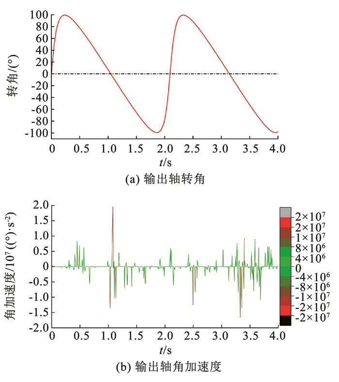
为验证齿面方程以及轮系设计的合理性,利用Adams对其进行了动力学仿真,得到输出摆角和输出角加速度幅值曲线如图 4所示。由图 4(a)输出摆角可知,当输入轴以匀角速度朝一个方向连续转动时,输出轴作往复摆动,满足机械式无切换换向装置的设计要求。由图 4(b)可知角加速度有剧烈波动现象,这表明,在非圆齿轮行星轮系运转过程中产生了冲击与振动,这主要由非圆齿轮齿廓差异性和齿侧间隙时变性所造成的。
|
图 4 非圆齿轮行星轮系运动仿真 Fig. 4 Motion simulation of non-circular planetary gear systems |
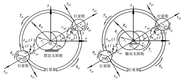
为探究非圆齿轮行星轮系在运转过程中的振动及动力学特性,在综合考虑时变啮合刚度、齿侧间隙、静态传递误差、黏弹性阻尼以及动态激励等因素后建立了如图 5所示的非圆齿轮行星轮系扭转动力学模型。
|
图 5 非圆齿轮行星轮系扭转动力学模型 Fig. 5 Torsional dynamic model of double planet row non-circular gear transmission systems |
考虑到非线性微分方程组含有大量位移耦合项,造成非线性微分方程组求解困难。为消除位移耦合影响,引入相对位移坐标:
| $ \left\{\begin{array}{l} x_{\mathrm{sp} i}=r_{\mathrm{bsp} i}\left(\theta_{\mathrm{p} i}+\theta_{\mathrm{H}}\right)+r_{\mathrm{bs}} \theta_{\mathrm{H}}-e_{\mathrm{sp} i}(\bar{t}) \\ x_{\mathrm{cp} i}=r_{\mathrm{bcp} i}\left(\theta_{\mathrm{p} i}+\theta_{\mathrm{H}}\right)+r_{\mathrm{bc}}\left(\theta_{\mathrm{H}}-\theta_{\mathrm{c}}\right)-e_{\mathrm{sp} i}(\bar{t}) \end{array}\right. $ | (10) |
根据相对位移坐标及轮系啮合原理,推导出其非线性动力学程组:
| $ \left\{\begin{array}{l} I_{\mathrm{pH}} \ddot{\theta}_{\mathrm{H}}=T_{\mathrm{H}} \\ m_{\mathrm{p} 1} \ddot{x}_{\mathrm{sp} 1}+\tau_1\left(c_{\mathrm{sp1}} \dot{x}_{\mathrm{sp} 1}+k_{\mathrm{sp} 1} f\left(x_{\mathrm{sp1}}\right)\right)+ \\ \tau_3\left(c_{\mathrm{cp} 1} \dot{x}_{\mathrm{cp1}}+k_{\mathrm{cp} 1} f\left(x_{\mathrm{cp1}}\right)\right)=-m_{\mathrm{p} 1} \ddot{e}_{\mathrm{sp1}}(\bar{t}) \\ m_{\mathrm{p} 2} \ddot{x}_{\mathrm{sp} 2}+\tau_2\left(c_{\mathrm{sp} 2} \dot{x}_{\mathrm{sp} 2}+k_{\mathrm{sp} 2} f\left(x_{\mathrm{sp} 2}\right)\right)+ \\ \tau_4\left(c_{\mathrm{cp} 2} \dot{x}_{\mathrm{cp} 2}+k_{\mathrm{cp} 2} f\left(x_{\mathrm{cp} 2}\right)\right)=-m_{\mathrm{p} 2} \ddot{e}_{\mathrm{sp} 2}(\bar{t}) \\ m_{\mathrm{c}}\left(\ddot{x}_{\mathrm{cp1} }+\ddot{x}_{\mathrm{cp} 2}\right)+\tau_3\left(c_{\mathrm{cp1}} \dot{x}_{\mathrm{cp1}}+k_{\mathrm{cp} 1} f\left(x_{\mathrm{cp1}}\right)\right)+ \\ \tau_4\left(c_{\mathrm{cp} 2} \dot{x}_{\mathrm{cp} 2}+k_{\mathrm{cp} 2} f\left(x_{\mathrm{cp} 2}\right)\right)=\frac{T_{\mathrm{c}}}{r_{\mathrm{c}}}-m_{\mathrm{c}}\left(\ddot{e}_{\mathrm{cp} 1}(\bar{t})+\ddot{e}_{\mathrm{cp} 2}(\bar{t})\right) \end{array}\right. $ | (11) |
式中:xspi、xcpi(i=1, 2)分别为固定太阳轮与行星轮、输出太阳轮与行星轮沿啮合线方向的相对位移,下标含b的参量为其基圆半径;IpH为行星架和行星轮总的转动惯量; mpi(i=1, 2)、mc分别为行星轮和输出太阳轮质量; cspi、ccpi、kspi、kcpi(i=1, 2)分别为固定太阳轮与行星轮、输出太阳轮与行星轮之间的啮合阻尼和时变啮合刚度; Tc为输出太阳轮和负载转矩之和。将式(11)转化成矩阵形式为
| $ \boldsymbol{M} \ddot{\boldsymbol{X}}+\boldsymbol{C} \dot{\boldsymbol{X}}+\boldsymbol{K} \boldsymbol{Y}=\boldsymbol{F} $ | (12) |
令
| $ \begin{gathered} \boldsymbol{X}=\left[\begin{array}{c} x_{\mathrm{H}} \\ x_{\mathrm{sp} 1} \\ x_{\mathrm{sp} 2} \\ x_{\mathrm{cp} 1} \\ x_{\mathrm{cp} 2} \end{array}\right] \\ \boldsymbol{Y}=\left[\begin{array}{l} x_{\mathrm{H}} \\ f\left(x_{\mathrm{sp1}}\right) \\ f\left(x_{\mathrm{sp} 2}\right) \\ f\left(x_{\mathrm{cp1}}\right) \\ f\left(x_{\mathrm{cp} 2}\right) \end{array}\right] \\ \boldsymbol{M}=\left[\begin{array}{lllll} m_{\mathrm{pH}} & & & & \\ & m_{\mathrm{p} 1} & & & \\ & & m_{\mathrm{p} 2} & & \\ & & & m_{\mathrm{c}} & \\ & & & & m_{\mathrm{c}} \end{array}\right] \\ \boldsymbol{C} =\left[\begin{array}{ccccc} 0 & 0 & 0 & 0 & 0 \\ 0 & \tau_1 c_{\mathrm{sp} 1} & 0 & \tau_3 c_{\mathrm{cp} 1} & 0 \\ 0 & 0 & \tau_2 c_{\mathrm{sp} 2} & 0 & \tau_4 c_{\mathrm{cp} 2} \\ 0 & 0 & 0 & \tau_3 c_{\mathrm{cp1}} & 0 \\ 0 & 0 & 0 & 0 & \tau_4 c_{\mathrm{cp1}} \end{array}\right] \\ \boldsymbol{K} =\left[\begin{array}{ccccc} 0 & 0 & 0 & 0 & 0 \\ 0 & \tau_1 k_{\mathrm{sp1}} & 0 & \tau_3 k_{\mathrm{cp} 1} & 0 \\ 0 & 0 & \tau_2 k_{\mathrm{sp} 2} & 0 & \tau_4 k_{\mathrm{cp} 2} \\ 0 & 0 & 0 & \tau_3 k_{\mathrm{cp} 1} & 0 \\ 0 & 0 & 0 & 0 & \tau_4 k_{\mathrm{cp} 2} \end{array}\right] \\ \boldsymbol{F}=\left[\begin{array}{c} \overline{F}_{\mathrm{H}} \\ -m_{\mathrm{p} 1} \ddot{e}_{\mathrm{sp} 1}(\bar{t}) \\ -m_{\mathrm{p} 2} \ddot{e}_{\mathrm{sp} 2}(\bar{t}) \\ \overline{F}-m_{\mathrm{c}} \ddot{e}_{\mathrm{cp} 1}(\bar{t}) \\ \overline{F}-m_{\mathrm{c}} \ddot{e}_{\mathrm{cp} 2}(\bar{t}) \end{array}\right]=\left[\begin{array}{c} \overline{F}_{\mathrm{H}} \\ 0 \\ 0 \\ \overline{F} \\ \overline{F} \end{array}\right]-\left[\begin{array}{c} 0 \\ m_{\mathrm{p} 1} \ddot{e}_{\mathrm{sp} 1}(\bar{t}) \\ m_{\mathrm{p} 2} \ddot{e}_{\mathrm{sp} 2}(\bar{t}) \\ m_{\mathrm{c}} \ddot{e}_{\mathrm{cp} 1}(\bar{t}) \\ m_{\mathrm{c}} \ddot{e}_{\mathrm{cp} 2}(\bar{t}) \end{array}\right] \end{gathered} $ | (13) |
式中: 摩擦系数函数τj=1+λjμ,其中λi为方向函数,μ为摩擦因数。
进行无量纲化简化可得:
| $ \ddot{\boldsymbol{X}}+\boldsymbol{C}_1 \dot{\boldsymbol{X}}+\boldsymbol{K}_1 \boldsymbol{Y}=\boldsymbol{F}_1 $ | (14) |
| $ \boldsymbol{C}_1=\left[\begin{array}{ccccc} 0 & 0 & 0 & 0 & 0 \\ 0 & \xi_1 & 0 & \xi_3 & 0 \\ 0 & 0 & \xi_2 & 0 & \xi_4 \\ 0 & 0 & 0 & \xi_3 & 0 \\ 0 & 0 & 0 & 0 & \xi_4 \end{array}\right]+\mu\left[\begin{array}{ccccc} 0 & 0 & 0 & 0 & 0 \\ 0 & \lambda_1 \xi_1 & 0 & \lambda_3 \xi_3 & 0 \\ 0 & 0 & \lambda_2 \xi_2 & 0 & \lambda_4 \xi_4 \\ 0 & 0 & 0 & \lambda_3 \xi_3 & 0 \\ 0 & 0 & 0 & 0 & \lambda_4 \xi_4 \end{array}\right] $ | (15) |
| $ \begin{gathered} \boldsymbol{K}_{\mathrm{l}}=\left(1+k_{\mathrm{a}} \cos \left(\omega_{\mathrm{eh}} t\right)\right)\left[\left[\begin{array}{lllll} 0 & 0 & 0 & 0 & 0 \\ 0 & 1 & 0 & 1 & 0 \\ 0 & 0 & 1 & 0 & 1 \\ 0 & 0 & 0 & 1 & 0 \\ 0 & 0 & 0 & 0 & 1 \end{array}\right]+\right. \\ \mu\left[\begin{array}{ccccc} 0 & 0 & 0 & 0 & 0 \\ 0 & \lambda_1 & 0 & \lambda_3 & 0 \\ 0 & 0 & \lambda_2 & 0 & \lambda_4 \\ 0 & 0 & 0 & \lambda_3 & 0 \\ 0 & 0 & 0 & 0 & \lambda_4 \end{array}\right] \end{gathered} $ | (16) |
| $ \boldsymbol{F}_1=\left[\begin{array}{c} F_{\mathrm{H}} \\ 0 \\ 0 \\ F_{\mathrm{m}} \\ F_{\mathrm{m}} \end{array}\right]+\left[\begin{array}{c} 0 \\ 0 \\ 0 \\ F_{\mathrm{ah}} \\ F_{\mathrm{ah}} \end{array}\right] \omega_{\mathrm{eh}}^2 \sin \left(\omega_{\mathrm{eh}} t\right) $ | (17) |
由于非圆齿轮齿廓差异性,致使目前没有完整的非圆齿轮时变啮合刚度数值解的计算方法。本文基于ISO standard 6336-1 (2019),采用等效齿数的变化来表征非圆齿轮副啮合过程中的节曲线半径变化的方法[18],计算非圆齿轮时变啮合刚度。则啮合刚度为:
| $ k=\frac{1}{q} B C_{\mathrm{m}} C_{\mathrm{R}} $ | (18) |
| $ \left\{\begin{array}{l} Z_{\mathrm{e} 1}=\frac{2 a\left(1-k^2\right)\left[\left(1-k \cos \theta_1\right)^2+k^2 \sin \theta_1\right]^{\frac{3}{2}}}{m\left(1-k \cos \theta_1\right)^3} \\ Z_{\mathrm{e} 2}=\frac{2 a\left(1-k^2\right)\left[\left(1+k \cos \theta_2\right)^2+k^2 \sin \theta_2\right]^{\frac{3}{2}}}{m\left(1-k \cos \theta_2\right)^3} \end{array}\right. $ | (19) |
| $ \begin{aligned} q= & 0.047\;23+\frac{0.155\;10}{Z_{\mathrm{e} 1}}+\frac{0.257\;91}{Z_{\mathrm{e} 2}}-0.006\;35 x_1- \\ & \frac{0.116\;54 x_1}{Z_{\mathrm{e} 1}}-0.001\;93 x_2-\frac{0.241\;88 x_2}{Z_{\mathrm{e} 2}}+ \\ & 0.005\;29 x_1^2+0.001\;82 x_2^2 \end{aligned} $ | (20) |
式中: q为单位齿宽柔度,Cm为误差修正系数, Ze1、Ze2为主、从动轮等效齿数, x1、x2为主、从动轮齿廓修形系数。
由式(18)~(20)可计算出非圆齿轮副的时变啮合刚度,将其拟合成傅里叶展开式形式为
| $ k(t)=k_{\mathrm{m}}+\sum\limits_{N=1}^{\infty}\left[k_{2 N} \cos \left(n \omega_N t\right)+k_{2 N+1} \sin \left(n \omega_N t\right)\right] $ | (21) |
式中:km为平均啮合刚度,k2N、k2N+1为傅里叶系数。
非圆齿轮的啮合阻尼可表示为:
| $ c=2 \xi \sqrt{\frac{k(t)}{\frac{r_{\mathrm{b} 1}^2}{I_1}+\frac{r_{\mathrm{b} 2}^2}{I_2}}}, \xi=\frac{c}{2 m_{\mathrm{e}} \sqrt{\frac{k_{\mathrm{m}}}{m_{\mathrm{e}}}}} $ | (22) |
式中:rb1、rb2分别为轮系中两对啮合的非圆齿轮主、从动轮基圆半径,ξ为阻尼比。
2.2.2 齿面摩擦由于非圆齿轮在啮合过程中存在齿面摩擦,因此,在建立非圆齿轮行星轮系动力学模型时,需考虑摩擦力与摩擦力矩对系统的影响。齿面摩擦力可表示为:
| $ F_{\mathrm{f}}=\lambda_j \mu F_{\mathrm{n}} $ | (23) |
| $ \lambda_j=\left\{\begin{array}{l} \operatorname{sgn}\left[L_{\mathrm{s} 1}(\bar{t}) \omega_{\mathrm{s}}-L_{\mathrm{sp} 1}(\bar{t}) \omega_{\mathrm{p} 1}\right], j=1 \\ \operatorname{sgn}\left[L_{\mathrm{s} 2}(\bar{t}) \omega_{\mathrm{s}}-L_{\mathrm{sp} 2}(\bar{t}) \omega_{\mathrm{p} 2}\right], j=2 \\ \operatorname{sgn}\left[L_{\mathrm{rp} 1}(\bar{t}) \omega_{\mathrm{p} 1}-L_{\mathrm{c} 1}(\bar{t}) \omega_{\mathrm{c}}\right], j=3 \\ \operatorname{sgn}\left[L_{\mathrm{rp} 2}(\bar{t}) \omega_{\mathrm{p} 2}-L_{\mathrm{c} 2}(\bar{t}) \omega_{\mathrm{c}}\right], j=4 \end{array}\right. $ | (24) |
式中sgn[]为方向函数。
根据齿轮啮合原理与轮齿间的几何关系,可确定非圆齿轮行星轮系中各轮齿的摩擦力力臂为
| $ \left\{\begin{array}{l} L_{\mathrm{sp} i}=\sqrt{\left(\rho_{\mathrm{sp} 1}+m\right)^2-\left(\rho_{\mathrm{sp} i} \cos \alpha\right)^2}-\left(\rho_{\mathrm{s}}+\rho_{\mathrm{sp} i}\right) \sin \alpha+\bmod \left(\omega_{\mathrm{p} i} r t, p_{\mathrm{b}}\right) \\ L_{\mathrm{s} i}=\sqrt{\left(\rho_{\mathrm{s}}+m\right)^2-\left(\rho_{\mathrm{s}} \cos \alpha\right)^2}-\left(\rho_{\mathrm{s}}+\rho_{\mathrm{sp} i}\right) \sin \alpha+\bmod \left(\omega_{\mathrm{s}} r t, p_{\mathrm{b}}\right) \\ L_{\mathrm{c} i}=\sqrt{\left(\rho_{\mathrm{c}}+m\right)^2-\left(\rho_{\mathrm{c}} \cos \alpha\right)^2}-\left(\rho_{\mathrm{c}}+\rho_{\mathrm{cp} i}\right) \sin \alpha+\bmod \left(\omega_{\mathrm{c}} r t, p_{\mathrm{b}}\right) \\ L_{\mathrm{cp} i}=\sqrt{\left(\rho_{\mathrm{cp} 1}+m\right)^2-\left(\rho_{\mathrm{cp} i} \cos \alpha\right)^2}-\left(\rho_{\mathrm{c}}+\rho_{\mathrm{cp} i}\right) \sin \alpha+\bmod \left(\omega_{\mathrm{p} i} r t, p_{\mathrm{b}}\right) \end{array}\right. $ | (25) |
式中:L为摩擦力力臂,ρ为曲率半径,pb为分度圆齿距,α为刀具齿形角。
非圆渐开线直齿轮的齿面法向力为[19]
| $ F_{\mathrm{n}}=\frac{T(t) \sqrt{r_1^2+r_2^2}}{r_1\left(a-r_1\right) \cos \alpha} $ | (26) |
式中T(t)为从动轮转矩。
综合误差用傅里叶级数表示为
| $ e(t)=e_{\mathrm{m}}+\sum\limits_{N=1}^{\infty}\left[e_{2 N} \cos \left(n \omega_N t\right)+e_{2 N+1} \sin \left(n \omega_N t\right)\right] $ | (27) |
式中: em为平均啮合误差,e2N、e2N+1为傅里叶系数,ωN为啮合频率。
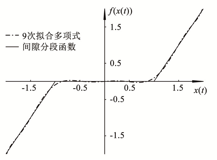
2.2.3 齿侧间隙齿侧间隙对于非圆齿轮传动系统具有重要作用,可保证非圆齿轮合理啮合,储存润滑油,形成润滑油膜,进而减缓磨损。但齿侧间隙也是造成非圆齿轮非线性振动的主要因素。针对非圆齿轮传动系统而言,啮合具有循序渐进渐退性即齿侧间隙值连续顺滑变化。若非圆齿轮传动系统齿侧间隙采用分段线性函数,将导致计算结果不精确。为此采用拟合的方式对其非线性函数进行优化。齿侧间隙非线性函数为
| $ f(x(t))= \begin{cases}x(t)-b, & x(t)>b \\ 0, & |x(t)|<b \\ x(t)+b, & x(t)<-b\end{cases} $ | (28) |
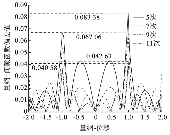
选取量纲-间隙b=1,进行多项式拟合计算,分别采用5次、7次、9次和11次进行拟合。随着拟合次数的增大,拟合曲线越来越平缓,拟合多项式相对于分段线性函数的偏差量也越来越小。
图 6为量纲-间隙函数拟合偏差图,当拟合多项式次数超过9次时,偏差量逐渐趋于稳定。相比于5次多项式拟合偏差值和7次多项式拟合偏差值,9次多项式拟合偏差值误差更小且拟合程度更好。但次数越高,偏差值振荡现象越剧烈。9次多项式拟合偏差值和11次多项式拟合偏差值浮动范围基本一致,但在区间[-1, 1]上,11次多项式拟合偏差值误差大于9次,出现过拟合现象,拟合精度下降。
|
图 6 量纲-间隙函数拟合偏差 Fig. 6 Deviation of dimensional-tooth clearance function fitting deviation |
综上所述,9次拟合多项式已足以反映非圆齿轮非线性侧隙函数的总体趋势, 其拟合效果图如图 7所示。
|
图 7 间隙函数拟合 Fig. 7 Clearance function fitting diagram |
结合实际情况与误差对比,采用9次拟合多项式替代齿侧间隙分段函数,其表达式为
| $ \begin{aligned} f(x(t))= & 0.016\;3 x^9(t)-0.154\;8 x^7(t)+0.470\;4 x^5(t)- \\ & 0.332\;0 x^3(t) +0.047\;3 x(t) \end{aligned} $ | (29) |
采用四阶变步长Runge-Kutta法对非圆齿轮行星轮系的微分方程组进行求解,获取了系统的分岔图、时域图、相平面轨迹和poincaré映射,以此来研究参数激励下非圆齿轮行星轮系的非线性响应特性。
3.1 阻尼对系统动态特性的影响非圆齿轮在啮合过程中由于塑性变形和润滑油膜会导致能量损耗,这种能量损耗现象被称之为啮合阻尼。为探究啮合阻尼对系统动态特性的影响,分别取不同的阻尼比进行分析。
图 8(a)为啮合方向位移相应随阻尼比变化的分岔图。在阻尼比取0.1附近时,啮合方向的位移相应波动范围急剧减小,系统从混沌运动进入稳定的拟周期运动。为进一步研究阻尼比对系统动态特性的影响,分别取ξ=0.05、ξ=0.20和ξ=0.30,结果如图 8(b)~8(d)所示。ξ=0.05时,时序图急剧波动,相图稍显杂乱,Poincaré截面图杂乱无章,系统处于混沌状态。ξ=0.20时,时序图整体呈规律波动,相图呈近闭合圆环曲面,Poincaré截面图有环形分布趋势,系统处于近拟周期运动状态。ξ=0.30时,时序图规律波动,相图呈闭合圆环曲面,Poincaré截面图呈环形分布,系统处于拟周期运动。

|
图 8 阻尼比对系统动态特性的影响 Fig. 8 Impact of damping ratio on system dynamic characteristics |
由图 8中时序图变化分析可得,阻尼比对幅值有一定抑制作用。阻尼比取较小值时,混沌运动占主导运动;随阻尼比的增大,系统逐渐处于稳定状态。因此,在一定范围内增大阻尼比,可使轮系快速进入稳定周期运动状态。由式(18)可知,阻尼与阻尼比成正比,因此,可利用阻尼比对系统的动态特性响应规律,指导齿面附加阻尼层设计[20],提高系统阻尼使轮系运转更加稳定。
3.2 齿面摩擦对系统动态特性的影响在非圆齿轮啮合的过程中,轮齿间并非纯滚动,而是啮合中的两齿面呈摩擦滚动状态,因此摩擦对系统动态特性的影响是不可忽视的。为探究摩擦对系统动态特性的影响,就摩擦因数取值不同做了以下研究。
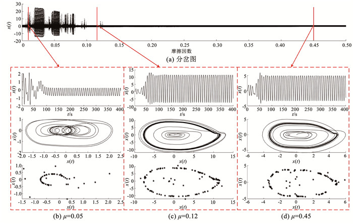
图 9(a)为啮合方向位移相应摩擦因数变化的分岔图,当摩擦因数增大到0.085时啮合方向位移发生突变,最大值和波峰值波动范围大幅减小,即系统运动形式发生改变,由混沌运动状态变化为拟周期运动状态。为进一步研究摩擦因数对系统动态特性的影响,分别取μ=0.01、μ=0.12和μ=0.45,结果如图 9(b)~9(d)所示。当μ=0.01时,相图和Poincaré截面图显示系统处于混沌运动状态;当μ=0.12和μ=0.45时,相图呈闭合圆环,Poincaré截面呈环状分布,系统处于拟周期运动状态。
|
图 9 摩擦因数对系统动态特性的影响 Fig. 9 Impact of friction factor on dynamic characteristics of the system |
综上所述,非圆齿轮行星轮系对摩擦因数较为敏感,当摩擦因数过小,会导致系统表现为混沌-周期状态交替存在,且位移响应幅值整体呈递减趋势。摩擦因数对系统的动态响应规律,可指导非圆齿轮行星轮系材料、压力角、润滑条件等相关参数的设计。由式(26)可知,适当增加压力角可提高齿面法向力,进而增大系统摩擦力,使系统运转更稳定。
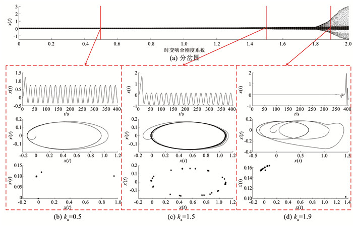
3.3 时变啮合刚度对系统动态特性的影响通过改变时变啮合刚度系数,可得到刚度激励下的系统动态响应如图 10所示。由图 10(a)分岔图可知,当ka>1.8时系统位移幅值急剧波动,出现分岔现象,系统进入混沌状态。为进一步研究啮合刚度系数对动态特性的影响,分别取ka=0.5、ka=1.5和ka=1.9,结果如图 10(b)~10(d)所示。ka= 0.5时,Poincaré截面图集中在某一区域,系统处于混沌运动;ka=1.5时,相图呈闭合环形曲线,Poincaré截面图呈环形分布,系统处于拟周期运动;ka=1.9时,时序图急剧波动,Poincaré截面图呈散乱分布,相图杂乱无章,系统处于混沌状态。
|
图 10 啮合刚度系数对系统动态特性的影响 Fig. 10 Impact of mesh stiffness coefficient on dynamic characteristics of the system |
当啮合刚度系数过大时,系统趋于混沌。适当增大时变啮合刚度系数,有利于提高系统稳定性;根据时变啮合刚度系数对系统的动态响应规律,可在理论上指导非圆齿轮的节曲线偏心率、齿顶高系数、压力角等设计参数的选择。例如,对齿面进行特殊热处理,增大节曲线偏心率和齿顶高系数等,提高时变啮合刚度,使非圆齿轮行星轮系平稳运转。
4 结论1) 在阻尼比取值较小时,系统混沌运动占主导运动,合理增大阻尼比,有利于轮系快速进入稳定周期运动状态。阻尼比对系统动态特性响应规律,可为齿面附加阻尼层设计提供理论依据。
2) 非圆齿轮行星轮系对摩擦因数较为敏感,当摩擦因数较小时,系统表现为混沌-周期状态交替存在,且位移响应幅值整体呈递减趋势。
3) 当啮合刚度系数过大时,系统趋于混沌;适当增大时变啮合刚度系数,有利于提高系统稳定性。时变啮合刚度系数对系统的动态响应规律,可为工程试验中扭矩、转速等实际工况条件的选取提供一定指导。
| [1] |
李渤涛, 陈定方. 非圆齿轮设计、制造、检测及应用[J]. 机械工程学报, 2020, 56(9): 55. LI Botao, CHEN Dingfang. Design, manufacture, inspection and application of non-circular gears[J]. Journal of Mechanical Engineering, 2020, 56(9): 55. DOI:10.3901/JME.2020.09.055 |
| [2] |
BURROWS M, SUTTON G. Interacting gears synchronize propulsive leg movements in a jumping insect[J]. Science, 2013, 341(6151): 1254. DOI:10.1126/science.1240284 |
| [3] |
LIN Chao, RAN Gui, HU Yanan. Compound motion characteristics analysis of eccentric herringbone curve-face gear pair[J]. Journal of Mechanical Science and Technology, 2021, 35(12): 5571. DOI:10.1007/s12206-021-1128-5 |
| [4] |
CHEN Siyu, TANG Jinyuan, LUO Caiwang, et al. Nonlinear dynamic characteristics of geared rotor bearing systems with dynamic backlash and friction[J]. Mechanism and Machine Theory, 2011, 46(4): 466. DOI:10.1016/j.mechmachtheory.2010.11.016 |
| [5] |
YI Yong, HUANG Kang, XIONG Yangshou, et al. Nonlinear dynamic modelling and analysis for a spur gear system with time-varying pressure angle and gear backlash[J]. Mechanical Systems and Signal Processing, 2019, 132: 18. DOI:10.1016/j.ymssp.2019.06.013 |
| [6] |
魏静, 吕程, 孙伟, 等. NGW型行星轮系模态特性及参数敏感性研究[J]. 振动工程学报, 2013, 26(5): 654. WEI Jing, LV Cheng, SUN Wei, et al. Study on the mode characteristics and parameter sensitivity for NGW planetary gear system[J]. Journal of Vibration Engineering, 2013, 26(5): 654. DOI:10.16385/j.cnki.issn.1004-4523.2013.05.015 |
| [7] |
王鑫, 徐玉秀, 武宝林, 等. 行星轮系故障状态下分岔与混沌特性分析[J]. 机械科学与技术, 2017, 36(3): 359. WANG Xin, XU Yuxiu, WU Baolin, et al. Bifurcation and chaos characteristics of planetary gear train with fault[J]. Mechanical Science and Technology for Aerospace Engineering, 2017, 36(3): 359. DOI:10.13433/j.cnki.1003-8728.2017.0306 |
| [8] |
ZGHAL B, GRAJA O, DZIEDZIECH K, et al. A new modeling of planetary gear set to predict modulation phenomenon[J]. Mechanical Systems and Signal Processing, 2019, 127: 234. DOI:10.1016/j.ymssp.2019.02.044 |
| [9] |
HUANG Kang, XIONG Yangshou, WANG Tao, et al. Research on the dynamic response of high-contact-ratio spur gears influenced by surface roughness under EHL condition[J]. Applied Surface Science, 2017, 392: 8. DOI:10.1016/j.apsusc.2016.09.009 |
| [10] |
李晟, 吴庆鸣, 张志强, 等. 两级行星轮系分岔与混沌特性研究[J]. 中国机械工程, 2014, 25(7): 931. LI Sheng, WU Qingming, ZHANG Zhiqiang, et al. Bifurcation and chaos characteristics of two-stage planetary gear train sets[J]. China Mechanical Engineering, 2014, 25(7): 931. DOI:10.3969/j.issn.1004-132X.2014.07.015 |
| [11] |
WANG Song, CAO Yunyu. Analysis of planetary gear transmission characteristics based on ANSYS[J]. Journal of Engineering Research and Reports, 2022, 23(1): 22. DOI:10.9734/jerr/2022/v23i117588 |
| [12] |
刘大伟, 谭万鑫, 金昕, 等. 变速椭圆齿轮泵的非线性振动模型与拍击特性[J]. 农业工程学报, 2021, 37(7): 15. LIU Dawei, TAN Wanxin, JIN Xin, et al. Nonlinear vibration model and rattling characteristics of elliptical gear pump with timing-varying input speed[J]. Transactions of the Chinese Society of Agricultural Engineering, 2021, 37(7): 15. DOI:10.11975/j.issn.1002-6819.2021.07.003 |
| [13] |
董长斌, 刘永平, 魏永峭, 等. 椭圆齿轮传动系统非线性动态特性分析[J]. 吉林大学学报(工学版), 2020, 50(2): 483. DONG Changbin, LIU Yongping, WEI Yongqiao, et al. Analysis of nonlinear dynamic characteristic of elliptic gear transmission system[J]. Journal of Jilin University (Engineering and Technology Edition), 2020, 50(2): 483. DOI:10.13229/j.cnki.jdxbgxb20181080 |
| [14] |
LIN Chao, WANG Yu, HU Yanan, et al. Nonlinear dynamic analysis of eccentric curve-face gear transmission system[J]. Journal of Sound and Vibration, 2022, 520: 116596. DOI:10.1016/j.jsv.2021.116596 |
| [15] |
温芳, 党海钊, 蔡敢为, 等. 含摩擦的椭圆齿轮非线性动态特性分析[J]. 机械传动, 2021, 45(5): 107. WEN Fang, DANG Haizhao, CAI Ganwei, et al. Analysis of nonlinear dynamic characteristic of elliptic gear with friction[J]. Journal of Mechanical Transmission, 2021, 45(5): 107. DOI:10.16578/j.issn.1004.2539.2021.05.016 |
| [16] |
华林. 非圆齿轮传动设计、制造与检测[M]. 武汉: 武汉理工大学出版社, 2019. HUA Lin. Noncircular gear transmission design, manufacturing and detection[M]. Wuhan: Wuhan University of Technology Press, 2019. |
| [17] |
吴序堂, 王贵海. 非圆齿轮及非匀速比传动[M]. 北京: 机械工业出版社, 1997. WU Xutang, WANG Guihai. Non-circular gear and non-uniform ratio transmission[M]. Beijing: China Machine Press, 1997. |
| [18] |
董长斌. 椭圆齿轮传动系统的啮合特性研究[D]. 兰州: 兰州理工大学, 2021 DONG Changbin. Study on meshing characteristics of elliptic gear transmission system[D]. Lanzhou: Lanzhou University of Technology, 2021. DOI: 10.27206/d.cnki.ggsgu.2021.001337 |
| [19] |
姚文席. 非圆齿轮设计[M]. 北京: 机械工业出版社, 2013. YAO Wenxi. Design of noncircular gear[M]. Beijing: China Machine Press, 2013. |
| [20] |
李辉. 大功率舰船用齿轮箱箱体结构的减振降噪方法研究[D]. 哈尔滨: 哈尔滨工业大学, 2020 LI Hui. Research on vibration and noise reduction method for high power marine gearbox housing structure[D]. Harbin: Harbin Institute of Technology, 2020. DOI: 10.27061/d.cnki.ghgdu.2020.001018 |
 2024, Vol. 56


