Solid propellants are high energetic materials which, during combustion, produce high temperature gaseous products. They are typically used in applications such as guns and rocket propulsion[1]. The energy and ballistic characteristics of solid propellants should be known, such as force, vivacity and co-volume, and the coefficient of burning rate law is very important in the development and evaluation of new propellant formulations, as well as in the quality control of large propellant production. These characteristic parameters also play a major role in the interior ballistic modeling, especially the intrinsic linear burning rate of the propellant, which is a central parameter for predicting the interior ballistic behavior of guns and rockets using computer simulations.
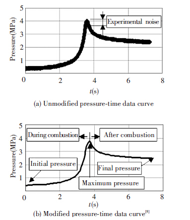
Experimentally, the determination of propellant burning rate can be accomplished through some sophisticated techniques[2], such as optical method[3], X-ray method[4], laser fractional light transmission[5], and microwave interferometry[6]. However, the conventional method using the closed bomb test[7] or strand burner[8] is more popular and has been widely used for the determination of propellant burning rates.This method consists of burning a small quantity of the propellant in a vessel of a constant volume and then acquiring the pressure versus time data. Examples of the pressure profile obtained in a closed bomb and strand burner are shown in Fig.1 and Fig.2, respectively.

|
Figure 1 Example of a closed vessel test result, in which the ignition time (tign) is indicated |
|
Figure 2 An example of pressure-time data curve |
The closed bomb and stand burner experimental methods have a few shortcomings. For instance, they require a substantial amount of hardware and sometimes need the utilization of expensive sensors, as well as the risk of manipulating the solid propellant which can be very hazardous. As a result, the computer modeling can provide a safe, fast, and economical alternative for evaluating the performance potential of solid propellants.Numerical modeling of closed vessel tests can be accomplished using numerical modeling for the interior ballistic of guns. In fact, the modeling of closed bomb tests represents a particular case of interior ballistic modeling of guns on which the projectile is fixed during the whole process. The existing code for interior ballistic modelization and simulation are of two classes: (1) lumped-parameter codes, also known as global-parameter codes or thermodynamic interior ballistic codes, such as IBHVG[9] and STANAG 4367[10]. (2) Local-parameter codes, also known as two-phase flow interior ballistic such as the one-dimensional code XNOVAKTC[11], and the multidimensional code NGEN3[12]. The local-parameter codes are more accurate and are the new trend for interior ballistics simulation. The most elaborate codes are built by military laboratories and industries for the simulation of interior ballistics of medium and large-caliber weapons. The access to such codes is restricted, and the development of similar codes takes decades and needs a lot of resources.
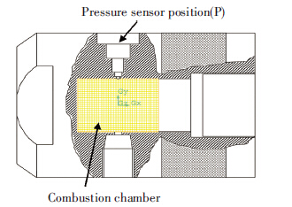
The available commercial CFD code-Fluent has been used in industry and engineering to simulate and analyze multiphase flow. It offers high quality flow calculation and highly detailed flow field visualization. Moreover, Fluent allows for the user to make some changes and integrate new codes (subroutines) to simulate specific problems. This work is the first step into the customization of Fluent to faithfully simulate the combustion of a solid propellant for interior ballistics of a small-caliber gun. It describes a computational technique for modeling the burning of propellant grains inside a closed volume. In this paper, in order to predict the pressure profile in the closed vessel (Fig.3), which is a key parameter in testing solid propellants characteristics, the combustion of the solid propellant is modeled by an Eulerian two-phase flow axisymmetric approach. Ideal gas law assumption and real gas law are both considered for the gas state equation. Then, the model is implemented into the commercial CFD code ANSYS FLUENT 14.5. The numerical results of the model for different solid propellants’ mass are compared with the experimental results reported in Ref.[13].
|
Figure 3 Closed-vessel apparatus |
2 Mathematical Model
The combustion modeling of the solid propellant in a closed vessel is based on unsteady, reactive two-phase flow with solid propellants, the combustion gases, and the ignition gases. Most of the existing models are based on one of two approaches[14]: the ensemble averaging approach and the Mixture-theory approach. The ensemble averaging approach is to treat the two flows of gas and particulates, and this method can be found in the Eulerian model in Fluent. In the Mixture-theory approach, the mixture is treated as one continuum flow consisting of two separate identifiable components, and this method is represented in Fluent by the Mixture model.
The combustion of the solid propellant in a closed vessel and in guns is a complex process. It is necessary to accept some assumptions to be able to model this process. The basic assumptions are: (1) the solid phase, which is composed of solid propellants, is considered as an incompressible pseudo-fluid; (2) the gas phase, which is composed of the propellants combustion gases, is considered as a compressible inviscid flow except for their action on the solid propellant particles via drag; (3) air in the chamber is neglected because the mass of the air is very small compared with the mass of combustion gas produced from the solid propellant; (4) the solid (propellant) burning results in a loss of mass from the solid phase and an equivalent gain by the gas phase; (5) the ignition is assumed to be perfect, i.e. all the solid propellant granules are simultaneously and uniformly ignited, and then all burn in parallel layers according to Piobert’s Law; (6) the walls are adiabatic.
2.1 Governing EquationsIn an Eulerian-Eulerian two-phase model, the gas and solids phases are treated as an interpenetrating continuum, identified by their phase fraction, and exchanging properties like momentum and energy. Each of these continua is described by means of equations of continuity and momentum[15].
The governing equations for the gas phase contain the terms of mass and energy generation by solid decomposition. The balance equations for mass, momentum, and energy of the gas phase are given by the following conservative-form equations[16]:
| ${\partial \over {\partial {\rm{t}}}}\left( {\alpha \rho } \right) + \nabla \cdot \left( {\alpha \rho .\overrightarrow u } \right) = \dot m$ | (1) |
| ${\partial \over {\partial {\rm{t}}}}\left( {\alpha \rho \overrightarrow u } \right) + \nabla \cdot \left( {\alpha \rho .\overrightarrow u \overrightarrow u } \right) = -\alpha \nabla p-\overrightarrow {{f_d}} + \dot m{\overrightarrow u _p}$ | (2) |
| ${\partial \over {\partial {\rm{t}}}}\left( {\alpha E} \right) + \nabla \cdot \left[ {\alpha \left( {E + p} \right)\overrightarrow u } \right] = -\overrightarrow {{f_d}} \overrightarrow {{u_p}} + \dot m\left( {{e_p} + {{{{\overrightarrow u }_p} \cdot {{\overrightarrow u }_p}} \over 2}} \right){q_p}$ | (3) |
where α is the gas volume fraction;ρ the gas density; u is the gas phase velocity vector; E is the total energy, and p is the pressure. The right side term of Eq.(1) represents the rate of the solid propellant’s decomposition. The right side momentum equation contains the interphase drag vector fd and the product of the solid decomposition rate by the solid phase velocity vector. In right side of the energy equation, ep represents the internal energy of the propellant, and qpaccounts for the heat transfer between phases. The subscript p in previous terms stands for the propellant.
The governing equations for the solid phase, which is considered as incompressible flow, are represented by the balance equation of momentum:
| ${\partial \over {\partial {\rm{t}}}}\left( {{\alpha _p}{\rho _p}\overrightarrow {{u_p}} } \right) + \nabla \cdot \left( {{\alpha _p}{\rho _p}{{\overrightarrow u }_p}{{\overrightarrow u }_p}} \right) = -{\alpha _p}\nabla p-{f_i} + {\overrightarrow f _d}-\dot m{\overrightarrow u _p}$ | (4) |
where αp is the solid volume fraction; ρp is the solid propellant density, and up is the solid phase velocity vector. The right side of Eq.(4) includes the intergranular force vector fi, plus the same terms, with opposite sign, of those appeared on the right side of the gas phase momentum equation.
2.2 Constitutive EquationsIn order to fully describe the system, additional equations are needed to determine some terms in previous equations. We use the constitutive laws to determine: the mass and energy exchanged between the phases, the interphase drag, the propellant combustion rate, etc.
2.2.1 Solid propellants combustionAs the volume of the solid propellant decreases by propellant combustion, the volume of the gas increases. The rate of decomposition of the solid propellant, in the control volume, is given by:
| $\dot m = \left( {1-\alpha } \right){\rho _p}{{{S_p}} \over {{V_p}}}r$ | (5) |
where α is the porosity; Sp is the particle surface; Vp is the particle volume; ρp is the solid density and r is the propellant linear burning rate which is modeled by Vieille’s law (also known as St. Roberts’ law),
| $r = A{p^n} + B$ | (6) |
where A, B and n are constants for a given propellant material.
2.2.2 Interphase dragThe interphase drag in the chamber is given by Ref.[12]. For spherical particle, the interphase drag has the following form,
| ${f_s} = {{1-\alpha } \over {{d_p}}}\rho \left( {u-{u_p}} \right)\left| {u-{u_p}} \right|{f_{sc}}$ | (7) |
where fsc and Re are given by
| ${f_{sc}} = {{2.5} \over {{{{\mathop{\rm Re}\nolimits} }^{0.0814}}}}{f_{s0}}, {\mathop{\rm Re}\nolimits} = {{\rho \left| {u = {u_p}} \right|{d_p}} \over \mu }$ | (8) |
The interphase heat transfer is given by Ref.[13], and can be written as:
| ${q_p} = {n_p}{S_p}q = \left( {1-\alpha } \right){{{S_p}} \over {{V_p}}}q$ | (9) |
| $q = h\left( {{T_g}-{T_p}} \right)$ | (10) |
where h is the thermal transfer coefficient. Tg is the temperature of the gas phase and Tp is the temperature of the solid particle.
2.2.4 State equationThe gas satisfies the real gas equation, known as the Nobel-Abel equation:
| $p = {{RT} \over {\left( {1/\rho -b} \right)}}$ | (11) |
where p is the pressure; T is the temperature; ρ is the gas density; b is the gas co-volume, and R is the gas constant. The commercial Fluent CFD code requires eight thermodynamic functions which must be derived from the state equation. These functions are put into Fluent-acceptable form by Ref.[17].
For the 2D axisymmetric calculation method, the governing equation for the gas and solid phase formed from Eqs.(1)-(4) can be written as[18]:
| ${{\partial Q} \over {\partial t}} + {{\partial F} \over {\partial x}} + {{\partial G} \over {\partial y}} + H = S$ | (12) |
where Q is the conservative vector; F and G are the convective fluxes, and S is the sources terms. The detailed form of these quantities is given by:
| $Q = \left( {\matrix{ {\alpha \rho } \cr {\alpha pu} \cr {\alpha pv} \cr {\alpha E} \cr {{\alpha _p}{\rho _p}{u_p}} \cr {{\alpha _p}{\rho _p}{v_p}} \cr } } \right), F = \left( {\matrix{ {\alpha pu} \cr {\alpha p{u^2} + \alpha p} \cr {\alpha puv} \cr {\alpha \left( {E + p} \right)u} \cr {{\alpha _p}{\rho _p}u_p^2} \cr {{\alpha _p}{\rho _p}{u_p}{v_p}} \cr } } \right)$ |
| $G = \left( {\matrix{ {\alpha \rho v} \cr {\alpha \rho vu} \cr {\alpha \rho {v^2} + \alpha p} \cr {\alpha \left( {E + p} \right)v} \cr {{\alpha _p}{\rho _p}{v_p}{u_p}} \cr {{\alpha _p}{\rho _p}v_p^2} \cr } } \right), H = {1 \over y}\left( {\matrix{ {\alpha \rho v} \cr {\alpha \rho vu} \cr {\alpha \rho {v^2}} \cr {\alpha \left( {E + p} \right)v} \cr {{\alpha _p}{\rho _p}{u_p}{v_p}} \cr {{\alpha _p}{\rho _p}v_p^2} \cr } } \right)$ |
| $S = \left( {\matrix{ {\dot m} \cr {-{f_{sx}} + \dot m{u_p}} \cr {-{f_{sy}} + \dot m{v_p}} \cr {-{f_{sx}}{u_p}-{f_{sy}}{v_p} + \dot m\left( {{{u_p^2 + v_p^2} \over 2}} \right)-{q_p}} \cr {-{\alpha _\rho }{{\partial p} \over {\partial x}}-{f_{ix}} + {f_{sx}}-\dot m{u_p}} \cr {-{\alpha _\rho }{{\partial p} \over {\partial y}}-{f_{iy}} + {f_{sy}}-\dot m{u_p}} \cr } } \right)$ |
The standard Mixture and the Eulerian models of Fluent are not able to simulate the modeling of the propellant combustion presented above without extensive user customization. The implementation of: real gas Nobel-Abel equation of state (Eq.(11)) and its eight related functions, the burning rate (Eqs.(5), (6)), the interphase drag (Eqs.(7), (8)), interphase heat transfer (Eqs.(9), (10)), and the source terms (the S term in Eq.(12)) is accomplished through a set of C code subroutines written and incorporated into Fluent code as the User Defined Functions (UDF).
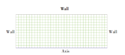
The finite volume method by Patankar[19] is used to solve the governing equations. The differential equations were discretized by a first-order upwind differencing scheme over the finite volume, and solved by the commercial CFD package Ansys Fluent V14.5 produced and owned by Ansys Inc. The velocity-pressure linkage is handled through the PISO algorithm for the Mixture model and by Coupled for the Eulerian model. The simulations are performed in a 2D Axisymmetric structured grid (Fig.4). A 2D mesh is produced in Gambit containing 442 cells of 0.002×0.002 m in size. The cell dimension has been chosen to be small enough to ensure a precise discretization of the computational domain, and large enough to ensure that several grains can be in one cell at the same time, i.e. the cell should be larger than the grain. A pre-simulation has shown that the pressure is independent of the grid. A very small adaptive time step (1×10⁻⁶ s to 1×10⁻⁹ s) with 25 iterations per time step is used. The numerical convergence criterion (as defined in Ansys Fluent 14.5) is set to 1×10⁻⁶ for energy and 1×10⁻³ for other scaled residual components. For the Mixture model, the underrelaxation factor equals to 1 and is adopted for all flow quantities, while for Eulerian model the default underrelaxation is kept unchanged. The materials properties and the operating conditions are summarized in Table1.
|
Figure 4 Combustion chamber mesh |
| Table 1 Materials properties and operating conditions |
4 Results and Discussion 4.1 Solid Propellant Mass mp=20.5 g
Firstly, the initial pressure of the solid propellant bed is set to be equal to 101 325 Pa for all models. The propellant charge of 20.5 g, which corresponds to a solid volume fraction of 0.1, is patched to the entire closed-vessel volume. The initial temperature is 298 K. The initial gas and solid velocities are null.
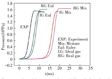
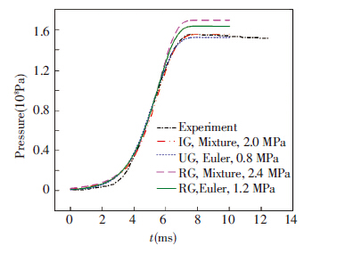
Fig.5 shows the pressure-time profile at the middle of the closed vessel (position (P) in Fig.3) during the combustion of 20.5 g of solid propellants. It displays the experimental profile of the pressure along with the numerical profiles predicted by the Mixture and Eulerian models using both the ideal gas assumption and the real gas law for the gas phase.
|
Figure 5 Pressure-time history at the middle of the closed vessel (P), for mp=20.5 g and P0=101 325 Pa |
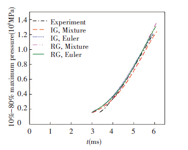
It seems that all models adequately predict the qualitative trend of the profiles of the pressure. They reproduce the rise of pressure and profile slope during the combustion as well as the maximum pressure. However, the time of the whole process is overestimated by all models especially by the Mixture model. This is due to the fact that the present code cannot simulate the ignition phase. Therefore, it is not able to predict the so called ignition delay (as shown in Fig.1). In the present code, the ignition of the solid propellant is assumed to start immediately. Codes for interior ballistic with this hypothesis set the initial chamber pressure as the mean chamber pressure when the ignition gases are uniformly injected into the gun chamber[14]. In other words, they replace the effect of the igniter by raising the initial pressure[20]. Since we do not dispose any numerical or experimental information on the ignition, a set of numerical simulation with different values of initial pressure are carried out. Values after fitting the initial pressure, as well as the new pressure profiles are shown in Fig.6. The curves can be divided into three parts: the early stage of combustion, which is associated with the ignition phase, is generally taken as the first 10% of maximum pressure (Fig.1). The combustion phase in the closed vessel test is used to determine the solid propellants parameters, generally taken as 10% to 80% of the maximum pressure. Finally, the end of the combustion determines the maximum pressure. For the first part, the profiles do not adequately fit the experimental profile, because they are out of the applicability of the Vieille’s Law, as well as the present code. This is due to the aforementioned ignition phase not being taken into account.
|
Figure 6 Pressure-time history at the middle of the closed vessel (P), for mp=20.5 g |
Fig.7 displays the second part. It can be seen that the numerical profiles fit the experimental pressure-time curve. For the last part of the curve, the predicted average maximum pressure is reported in Table2. Models using ideal gas assumption underestimate the maximum pressure by 0.1% and 1.9% for the Mixture and Eulerian model, respectively. Models using the real gas law overestimate the maximum pressure by 9.0% and 5.2% for the Mixture and Eulerian model, respectively.
|
Figure 7 10%-80% maximum pressure-time history at the middle of the closed vessel (P), for mp=20.5 g |
| Table 2 Calculated results of maximum average pressure by different models |
Although the code with the real gas law tends to predict a slightly higher maximum pressure than the measured value, it is quite justifiable by the fact that the simulation is adiabatic as the experience is subject to thermal losses. This can be clearly seen in Fig.6. After the pressure reaches the maximum pressure, it remains constant for the numerical simulation, while it starts to decrease in the experiment. The use of the ideal gas law assumption for the gas phase can be tolerated in the simulation of the closed vessel test with low or medium pressure, but it is preferable to use the real gas law instead. This is particularly true for the simulation of small closed vessels with high pressure or in the interior ballistic simulation of guns because at high pressure the properties and behaviors of the gases produced by the combustion from a solid propellant are far from those of ideal gasses. The discrepancy between the Mixture and Euler model can be attributed to the difference between them in the treatment of the solid and gas phases. The Mixture model is a simplification of the Euler model and it treats the solid and gases as one phase while the Euler model treats them as separate phases.
Both the Mixture model and Eulerian model can be used for the prediction of the pressure profile in a closed vessel test, however the use of the present code for the interior ballistic of a gun with the integration of the ignition phase needs the use of Eulerian model which is capable of showing the patterns of the flow, especially the spread of the flame wave through the solid propellant bed.
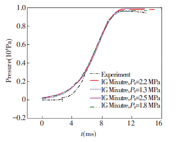
4.2 Solid Propellant Mass mp=12.8 gTo test the reliability of the code, another set of simulations are carried out for a small mass of solid propellants (mp=12.8 g). The results of the simulation and the experiment are shown in Fig.6. The code is still able to predict the pressure in agreement with the experiment.
|
Figure 8 Pressure⁃time history at the middle of the closed vessel (P), for mp = 12.8 g |
4.3 Gain Effect
The solid propellants particles used in guns have different shapes. The configuration of the propellant grain is very important because it determines the behavior of the propellant during the combustion, thus, the interior ballistic performance of the system. The solid propellants used in small-caliber guns usually have the shape of a disc, cylinder or sphere. Here, the present code is used to simulate the combustion of a solid propellant in a closed-vessel using three different shapes of particles of the same volume, namely, disc, cylinder and sphere.
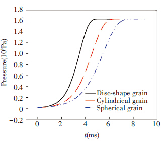
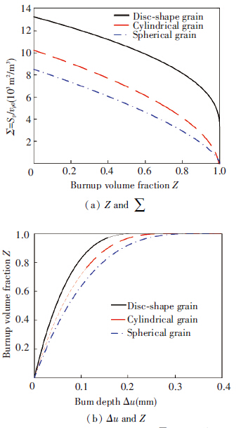
Fig.9 displays the pressure-time curve for the three grain shapes. Since the solid propellant in the three cases has the same mass and thermodynamic properties, the maximum pressure in the chamber is the same. However, the build-up of the pressure differs for different shapes of grains. The disc-shape grain is the fastest one while the spherical grain is the slowest. The shape of the propellant grain affects the pressure profile. This can be explained by the behavior of each propellant related to the burn-up volume fraction Z and the surface area per the initial volume ∑, which is shown in Fig.10.
|
Figure 9 Pressure-time history at the middle of the closed vessel (P), for mp=20.5 g |
|
Figure 10 Relationships between Z and ∑, and Δu and Z |
For all three shapes, the surface area of the propellant grains decreases as the burning progresses. At the beginning, a large total surface area is processed, which leads to a relatively fast initial production of gas because the gas production rate is directly proportional to the total surface area of all of the particles. As the burning progresses, the total surface area diminishes yielding to a reduction in the gas production rate. In the meantime, the burning rate is affected by the variation of pressure in the solid propellant bed as is stated in Eq.(6). At the end, the propellant grains are almost entirely consumed as its surface area drops to zero and the combustion stops. Propellant grains with this behavior are known as “degressive” propellants. During the combustion the disc-shape grain has the largest surface area which results in the corresponding fastest burning of the propellants. The spherical grain is the most degressive grain and the disc-shape grain the less degressive. In fact the ratio between the initial surface area and the final surface area is about 3, which means that the disc-shaped grain is almost neutral rather than degressive.
5 ConclusionsThe two-dimensional axisymmetric Eulerian numerical simulation in a closed vessel utilizing spherical single-component solid propellant granules is carried out using CFD code Ansys Fluent. The results of the simulation are compared with experimental data for validation. The history of the pressure of the closed vessel is in good agreement with the experimental data. The shape of propellant grains affects the energy release rate of the solid propellant. The model presented is capable in simulating the combustion of solid propellants inside closed-vessels, thus, it has the potential to simulate the interior ballistics inside gun systems. Expanding beyond the simulation of closed-vessel tests to gun systems need some improvements in the present model such as the modeling of the movement of the projectile and the ignition phase. These improvements will be the scope of the future work.
| [1] |
Thakre P, Yang V.
Solid propellants. John Wiley & Sons Ltd. 2010 : 1 -9.
( 0) 0)
|
| [2] |
Murphym J J, Fuchinoue R, Krier H. Transient solid propellant burning rate measurement techniques.
,1999, 1 : 527-538.
( 0) 0)
|
| [3] |
Eisenreich N, Kugler H P, Sinn F. An optical system for measuring the burning rate of solid propellant strands.
Propellant, Explosives, Pyrotechnics,1987, 12 (3) : 78-80.
( 0) 0)
|
| [4] |
Hasegawa H, Tokudome S, Hanzawa M, et al. Erosive burning of aluminized composite propellants: x-ray absorption measurement, correlation and application. Proceedings of 39th AIAA/ASME/SAE/ASEE Joint Propulsion Conference and Exhibit. Huntsville, 2003. AIAA paper No. 2003-4812.
( 0) 0)
|
| [5] |
Wang J, Sang B. Laser technique for determining solid propellant transient burning rates during oscillatory combustion.
Fuel,1998, 77 (15) : 1845-1849.
( 0) 0)
|
| [6] |
Bozic V S, Blagojevic D D, Anicin B A. Measurement system for determining solid propellant burning rate using transmission microwave interferometry.
Journal of propulsion and power,1998, 14 (4) : 421-428.
( 0) 0)
|
| [7] |
STANAG 4115. Definition and determination of ballistic properties of gun propellants. North Atlantic Council.ED.2, 1997.
( 0) 0)
|
| [8] |
Yilmaz N, Donaldson B, Gill W, et al. Solid propellant burning rate from strand burner pressure measurement.
Propellants, Explosives, Pyrotechnics,2008, 33 (2) : 109-117.
( 0) 0)
|
| [9] |
Ronald D A, Kurt D F. IBHVG2—A user’s guide: report of US Army Ballistic Research Laboratory, BRL-TR-2829. Aberdeen Proving Ground, MD, 1987.
( 0) 0)
|
| [10] |
STANAG 4367. Thermodynamic interior ballistic model with global parameters. North Atlantic Council, 2009.
( 0) 0)
|
| [11] |
Gough P S. The XNOVAKTC code: report of US Army Ballistic Research Laboratory, BRL-CR-627. Aberdeen Proving Ground, MD, 1990.
( 0) 0)
|
| [12] |
Nusca M J, Gough P S. Numerical model of multiphase flows applied to solid propellant combustion in gun systems. Proceedings of 34th IAA/ASME/SAE/ASEE Joint Propulsion Confernce & Exibit. Ceveland, OH, 1998. AIAA paper No. 98-3695.
( 0) 0)
|
| [13] |
Papy A.
Etude numérique de la balistique intérieur des armes de petite calibre. Free University of Brussels. 2005 .
( 0) 0)
|
| [14] |
Sung H G, Jang J S, Roh T S. Application of Eulerian—Lagrangian approach to gas-solid flows in interior ballistics. ASME Journal of Applied Mechanics, 2013, 80(3): Article ID 031407.
( 0) 0)
|
| [15] |
Gidaspow D. Multiphase Flow and Fluidization: Continuum and Kinetic Theory Descriptions. New York:Academic Press, 1994.
( 0) 0)
|
| [16] |
Miura H, Matsuo A. Numerical simulation of projectile accelerator using solid propellant. Proceedings of 44th AIAA Aerospace Sciences Meeting and Exhibit. Reno, NV, 2006.AIAA Paper No. 2006-1439.
( 0) 0)
|
| [17] |
Johnston I A. The Noble-Abel equation of state: thermodynamic derivations for ballistics modeling. Report of Weapon Systems Division, Defense Science and Technology Organization, DSTO-TN-0670. Australia, 2005.
( 0) 0)
|
| [18] |
Miura H, Mastuo A. Numerical simulation of solid propellant combustion in a gun chamber. Proceedings of 42nd AIAA/ASME/SAE/ASEE Joint Propulsion Conference & Exhibit. Sacramento, California, 2006. AIAA paper No. 2006-4955.
( 0) 0)
|
| [19] |
Patankar S V. Numerical Heat Transfer and Fluid Flow. Washington DC: Hemisphere Publishing Corporation, 1980.
( 0) 0)
|
| [20] |
Nussbaum J, Helluy P, Herard J M, et al. Numerical simulations of reactive two-phase gas-particle flows. Proceedings of 39th AIAA Thermophysics Conference, Miami, FL, 2007. AIAA Paper No. 2007-4161.
( 0) 0)
|
 2016, Vol. 23


