Numerical Simulation for Two-Phase Water Hammer Flows in Pipe by Quasi-Two-Dimensional Model
1 Introduction
The study of two-phase flows in pipelines is of great practical importance in water supply network systems. In general, when the liquid pressure in a pipeline drops to the dissolved gas saturation pressure or the vapor pressure, the flow regime is changed from single-phase (pure liquid) to two-phase (liquid-gas)[1-2]. The cavitation flows occurred in a pipe are distinguished as two cases; one is that the gaseous cavitation by a significant gas release occurs when the pressure is below the dissolved gas saturation pressure but above the vapor pressure and the other is that the vapor cavitation happens when the pressure drops to the vapor pressure of the liquid[2]. The vapor cavitation may occur as a discrete vapor cavity in a localized portion of the pipe or a distributed vaporous cavitation in a significant portion of the pipe[4]. The discrete (localized) vapor cavity is formed at a boundary or at a high point along the pipeline. If the vapor pressure extends over a significant portion of the pipe, the vapor cavitation forms the distributed vaporous cavitation. Therefore, the discrete vapor cavity model (DVCM), discrete gas cavity model (DGCM), and distributed vaporous cavitation model are mainly used to simulate two-phase flows in pipeline systems.
Previous research works have focused on the numerical simulation of two-phase water hammer flows. Bergant et al.[1-2], Simpson et al.[3-4], and Wylie et al.[5] presented a set of one-dimensional (1D) equations for two-phase water hammer flows and compared the numerical results with the experimental ones occurred by a rapid closure of a downstream valve in a sloping pipeline laboratory apparatus. Leon et al.[6] proposed a second-order shock- capturing scheme by finite volume method to simulate two-phase water hammer flows. Adamkowski et al.[7-8] presented the results of laboratory tests and visualization of the cavitation zones. Sumam et al.[9] proposed the use of 1D continuity and momentum equations for the homogeneous water-vapor mixture to simulate two-phase water hammer flows in a pipe. Urbanowicz et al.[10] proposed the modeling of instantaneous wall shear stress for two-phase water hammer flows. Himr[11] investigated the volume of cavity by means of the experiment and simulated numerically the 1D water hammer flow with the column separation. Zhou et al.[12] used both the experimental and numerical methods to simulate water hammer flows in a rapidly filling pipeline containing two entrapped air pockets. Pezzinga et al.[13] proposed a distributed two-dimensional (2D) model for analysis of transient vaporous cavitation in pipes.
Generally, the 1D model is commonly used to simulate two-phase water hammer flows. The 1D model is easy programming and has a good computational efficiency, but it underestimates both pressure heads and discharges due to the poor representation of the unsteady friction. Taking into account the velocity profile in the cross section of the pipe, the quasi-two-dimensional (quasi-2D) model[14-20] is able to analyze water hammer flows in a pipe more accurately than the 1D model.
This paper presents the numerical analysis of the two-phase water hammer flows with column separation in pipes by a numerical model including the quasi-2D model for pure liquid zone and the discrete gas cavity model for vaporous cavity zone with column separation. Due to the unsteady friction in water hammer flows, the dissipation is correctly evaluated by the proposed quasi-2D model. In a numerical test, the numerical results obtained by the proposed model are compared with these by the corresponding 1D model and the experimental ones provided by the literature[2], respectively.
2 Mathematical Model
2.1 Water Hammer Equations
Assuming that the flow is axially symmetric and the convective terms are negligible, the 2D governing equations for water hammer flows in a pipe may be expressed as[14]
|
$\frac{g}{{{a}^{2}}}\frac{\partial H}{\partial t}+\frac{\partial u}{\partial x}+\frac{1}{r}\frac{\partial \left( rv \right)}{\partial r}=0$
|
(1) |
|
$\frac{\partial u}{\partial t}+g\frac{\partial H}{\partial x}-\frac{1}{\rho r}\frac{\partial \left( r\tau \right)}{\partial r}=0$
|
(2) |
where x is the distance in axial direction of the pipe; r is the distance in radial direction from the pipe axis; t is the time; ρ is the liquid density; H is the pressure head; u and v are the axial and radial velocities, respectively; a is the wave speed; g is the gravitational acceleration, and τ is the total shear stress. The 1D water hammer equations are derived by integrating Eqs.(1) and (2) across the pipe section, yielding
|
$\frac{gA}{{{a}^{2}}}\frac{\partial H}{\partial t}+\frac{\partial Q}{\partial x}=0$
|
(3) |
|
$\frac{\partial Q}{\partial t}+gA\frac{\partial H}{\partial x}+\frac{\pi D{{\tau }_{w}}}{\rho }=0$
|
(4) |
with
|
$Q=\int\limits_{0}^{R}{2\pi rudr, }{{\tau }_{w}}=-{{\left( \rho {{v}_{T}}\frac{du}{dr} \right)}_{r}}=R$
|
where Q is the discharge; A is the cross-sectional area of the pipe; R and D are the radius and the diameter of the pipe, respectively; νT is the total viscosity, and τw is the wall shear stress.
2.2 Quasi-2D Model for Water Hammer Flow
The solution for water hammer flows in the pure liquid zone is estimated by a quasi-2D model using the method of characteristics (MOC). The characteristic forms of both 2D and 1D water hammer equations are given as
|
$\frac{\text{d}H}{\text{d}t}\pm \frac{a}{g}\frac{\text{d}u}{\text{d}t}+\frac{{{a}^{2}}}{g}\frac{1}{r}\frac{\partial \left( rv \right)}{\partial r}\mp \frac{a}{g}\frac{1}{\rho r}\frac{\partial \left( r\tau \right)}{\partial r}=0, \text{along}$
|
(5) |
|
$\frac{\text{d}H}{\text{d}t}\pm B\frac{\text{dQ}}{\text{d}t}\pm B\frac{\pi D{{\tau }_{w}}}{\rho }=0, \text{along d}x/\text{d}t=\pm a$
|
(6) |
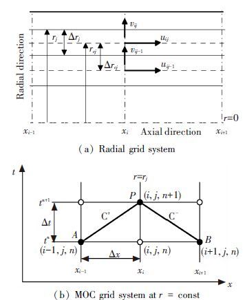
where B=a/gA. The computational domain for the discretization of characteristic equations is shown in Fig. 1(a). The pipe is discretized into Nr cylinders with varying thickness in the radial direction. The pipe length L is divided into Nx reaches of constant length Δx(=L/Nx) in the axial direction. The axial velocity u is located in the middle of each reaches in the radial direction and both radial velocity v and turbulent viscosity νT are located at the boundaries of each reaches in the radial direction. The time step Δt is computed by the equation Δt=Δx/a.
Integrating Eq.(5) on the characteristic lines between time t and t+Δt(Fig. 1(b)), the discretized forms of Eq.(5) may be expressed as
|
$\begin{align}
& {{H}_{p}}-{{H}_{A}}+\frac{a}{g}\left( {{u}_{p}}-{{u}_{A}} \right)+\theta {{\left[ \frac{\Delta t{{a}^{2}}}{g}\frac{1}{r}\frac{\partial \left( rv \right)}{\partial r} \right]}_{p}}+ \\
& \left( 1-\theta \right){{\left[ \frac{\Delta t{{a}^{2}}}{g}\frac{1}{r}\frac{\partial \left( rv \right)}{\partial r} \right]}_{A}}-\varepsilon {{\left[ \frac{\Delta ta}{g}\frac{1}{pr}\frac{\partial \left( r\tau \right)}{\partial r} \right]}_{p}}- \\
& \left( 1-\varepsilon \right){{\left[ \frac{\Delta ta}{g}\frac{1}{pr}\frac{\partial \left( r\tau \right)}{\partial r} \right]}_{A}}=0 \\
\end{align}$
|
(7) |
|
$\begin{align}
& {{H}_{p}}-{{H}_{B}}+\frac{a}{g}\left( {{u}_{p}}-{{u}_{B}} \right)+\theta {{\left[ \frac{\Delta t{{a}^{2}}}{g}\frac{1}{r}\frac{\partial \left( rv \right)}{\partial r} \right]}_{p}}+ \\
& \left( 1-\theta \right){{\left[ \frac{\Delta t{{a}^{2}}}{g}\frac{1}{r}\frac{\partial \left( rv \right)}{\partial r} \right]}_{B}}-\varepsilon {{\left[ \frac{\Delta ta}{g}\frac{1}{pr}\frac{\partial \left( r\tau \right)}{\partial r} \right]}_{p}}- \\
& \left( 1-\varepsilon \right){{\left[ \frac{\Delta ta}{g}\frac{1}{pr}\frac{\partial \left( r\tau \right)}{\partial r} \right]}_{B}}=0 \\
\end{align}$
|
(8) |
where ε and θ are the weight coefficients defining temporal discretization of the viscous term and radial flux term in the characteristic equations, respectively. Using the central difference scheme in the radial direction for both the viscous and radial flux terms in the above equations, the resulting equations are expressed as follows:
|
$\begin{align}
& H_{i}^{n+1}-\theta {{C}_{qj}}q_{i, j-1}^{n+1}+\theta {{C}_{qj}}q_{i, j}^{n+1}-\varepsilon {{C}_{u1j}}u_{i, j-1}^{n+1}+ \\
& \left( a/g+{{\varepsilon }_{u2j}} \right)u_{i, j}^{n+1}-\varepsilon {{C}_{u3j}}u_{i, j+1}^{n+1}={{K}_{pi, j}} \\
\end{align}$
|
(9) |
|
$\begin{align}
& H_{i}^{n+1}-\theta {{C}_{qj}}q_{i, j-1}^{n+1}+\theta {{C}_{qj}}q_{i, j}^{n+1}+\varepsilon {{C}_{u1j}}u_{i, j-1}^{n+1}- \\
& \left( a/g+{{\varepsilon }_{u2j}} \right)u_{i, j}^{n+1}+\varepsilon {{C}_{u3j}}u_{i, j+1}^{n+1}={{K}_{ni, j}} \\
\end{align}$
|
(10) |
with
|
$\begin{align}
& {{K}_{pi, j}}=H_{i-1}^{n}+\left( 1-\theta \right){{C}_{qj}}\left( q_{i-1, j-1}^{n}-q_{i-1, j}^{n} \right)+ \\
& \left( 1-\varepsilon \right)\times {{C}_{u1j}}u_{i-1, j-1}^{n}+\left[ a/g-\left( 1-\varepsilon \right){{C}_{u2j}} \right] \\
& u_{i-1, j}^{n}+\left( 1-\varepsilon \right){{C}_{u3j}}u_{i-1, j+1}^{n} \\
& {{K}_{ni, j}}=H_{i-1}^{n}+\left( 1-\theta \right){{C}_{qj}}\left( q_{i+1, j-1}^{n}-q_{i+1, j}^{n} \right)- \\
& \left( 1-\varepsilon \right)\times {{C}_{u1j}}u_{i+1, j-1}^{n}+\left[ a/g-\left( 1-\varepsilon \right){{C}_{u2j}} \right] \\
& u_{i+1, j}^{n}-\left( 1-\varepsilon \right){{C}_{u3j}}u_{i+1, j+1}^{n} \\
\end{align}$
|
where q(=rv) is the radial flux; the subscripts i and j indicate the axial and radial step indexes, respectively, and the superscript n denotes the time step index. The coefficients Cq, Cu1, Cu2 and Cu3 in the above equations may be expressed as
|
$\begin{align}
& {{C}_{qj}}=\frac{{{a}^{2}}\Delta t}{g{{r}_{cj}}\left( {{r}_{j}}-{{r}_{j-1}} \right)} \\
& {{C}_{u1j}}=\frac{a\Delta t{{v}_{Tj-1}}{{r}_{j-1}}}{g{{r}_{cj}}\left( {{r}_{cj}}-{{r}_{cj-1}} \right)\left( {{r}_{j}}-{{r}_{j-1}} \right)} \\
& {{C}_{u3j}}=\frac{a\Delta t{{v}_{Tj}}{{r}_{j}}}{g{{r}_{cj}}\left( {{r}_{cj+1}}-{{r}_{cj}} \right)\left( {{r}_{j}}-{{r}_{j-1}} \right)} \\
& {{C}_{u2j}}={{C}_{u1j}}+{{C}_{u3j}} \\
\end{align}$
|
where rj and rc j are the coordinates of the boundary and middle points of reaches in the radial direction, respectively. The source term Kpi, j and Kni, j are the known values, whose elements depend on H, u and q at the previous time level n. The equation for axial velocity is obtained by subtracting Eq.(9) from Eq.(10) and the equation for both pressure head and radial velocity is obtained by adding Eqs.(9) and (10) , respectively. The equation for axial velocity and the equation for both pressure head and radial flux may be given as
|
$\begin{align}
& \varepsilon {{C}_{u1j}}u_{i, j-1}^{n+1}-\left( a/g+{{\varepsilon }_{u2j}} \right)u_{i, j}^{n+1}+{{C}_{u3j}}u_{i, j+1}^{n+1}= \\
& 0.5\left( {{K}_{ni, j}}-{{K}_{pi, j}} \right) \\
\end{align}$
|
(11) |
|
$H_{i}^{n+1}-\theta {{C}_{qj}}\left( q_{i, j-1}^{n+1}-q_{i, j}^{n+1} \right)=0.5\left( {{K}_{pi, j}}+{{K}_{ni, j}} \right)$
|
(12) |
Both Eqs.(11) and (12) are the important ones of the quasi-2D model proposed by Zhao and Ghidaoui[17]. Both equations are the fully implicit equations in terms of the unknowns (u, H and q), and these solutions involve the inversions of the two Nr×Nr matrices with tri-diagonal.
For the proposed quasi-2D model, both the radial flux and pressure head are calculated by the individual explicit equations instead of using Eq.(12) . In fact, it is proved that the pressure head obtained by the step-by-step calculation of the radial flux in Eq.(12) is identical to one obtained by using the 1D characteristic equation (as shown in Appendix). Based on this fact, the pressure head is evaluated by the 1D characteristic Eq.(6) . If the pressure head at time level n+1 is known, the radial flux or radial velocity can be easily evaluated by using Eq. (12) , and these explicit equations may be expressed as
|
$q_{i, j}^{n+1}=\left[ \left( {{K}_{ni, j}}+{{K}_{pi, j}} \right)/2-H_{i}^{n+1} \right]\theta {{C}_{qj}}+q_{i, j-1}^{n+1}$
|
(13) |
or
|
$v_{i, j}^{n+1}=q_{i, j}^{n+1}/{{r}_{j}}$
|
(14) |
The discretized forms of 1D characteristic Eq. (6) are expressed as follows:
|
$H_{i}^{n+1}+BQ_{i}^{n+1}+\varepsilon \pi DtB\tau _{wi}^{n+1}/\rho ={{C}_{p}}$
|
(15) |
|
$H_{i}^{n+1}+BQ_{i}^{n+1}+\varepsilon \pi DtB\tau _{wi}^{n+1}/\rho ={{C}_{M}}$
|
(16) |
with
|
$\begin{align}
& {{C}_{p}}=H_{i-1}^{n}+BQ_{i-1}^{n}-\left( 1-\varepsilon \right)\pi DtB\tau _{wi-1}^{n}/\rho \\
& {{C}_{M}}=H_{i+1}^{n}+BQ_{i+1}^{n}-\left( 1-\varepsilon \right)\pi DtB\tau _{wi+1}^{n}/\rho \\
\end{align}$
|
Combining Eq.(15) with Eq.(16) , the pressure head and discharge may be obtained as
|
$H_{i}^{n+1}=\left( {{C}_{P}}+{{C}_{M}} \right)/2$
|
(17) |
|
$Q_{i}^{n+1}=\left( {{C}_{P}}+{{C}_{M}} \right)/2B-\varepsilon \pi DtB\tau _{wi}^{n+1}/\rho $
|
(18) |
The axial velocity calculated by Eq.(11) as the model of Zhao and Ghidaoui, is used to evaluate the wall shear stress. For the proposed model, two explicit equations for the pressure head and radial flux will reduce the computational number with respect to the solution of Eq.(12) . Moreover, the radial velocity in the water hammer analysis is usually neglected, and the computational efficiency can be improved by neglecting Eq.(13) for the radial flux.
2.3 Discrete Gas Cavity Model
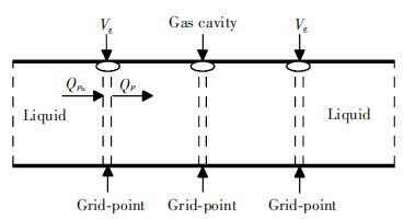
The vaporous cavitation zone with column separation may be successfully simulated by DGCM[1]. In DGCM, it is assumed that a small quantity of free air is concentrated at each grid point as shown in Fig. 2.
The regions between both grid points are assumed to be pure liquid without free gas, and the water hammer equations are valid for these regions. In the discrete gas cavity model, the gas void fraction α is very small as the order of 10-7 at the standard atmospheric condition, where α is the ratio between the volume of free gas Vg and the volume of the liquid-gas mixture Vm. Each isolated small volume of gas is assumed to be expanded and contracted isothermally as the pressure varies in accordance with the perfect gas law. Therefore, the gas void fraction α may be written as[1, 5]
|
$\alpha =\frac{{{M}_{g}}{{R}_{g}}T}{{{P}_{g}}{{R}_{g}}T}$
|
(19) |
where Mg is the mass of free gas; Rg is the specific gas constant, and T is the absolute temperature. Assuming that the mixture volume Vm in each reaches is constant, the volume of gas Vg may be expressed as[5]
|
${{V}_{g}}=\alpha {{V}_{m}}=\frac{{{P}_{g0}}{{\alpha }_{0}}{{V}_{m}}}{{{P}_{g}}}=\frac{C}{H-z-{{H}_{v}}}$
|
(20) |
where α0 is the gas void fraction at a given reference pressure pg0 for a constant mass of free gas; C = pg0α0Vm/ρg is a specified constant; H is the pressure head; z is the elevation of the centerline of the pipe; Hv=pv/ρg-Hb is the gage vapor pressure; Hb is the barometric pressure head, and pv is the absolute vapor pressure at reference temperature. A continuity equation[1] for the discrete gas volume may be given by
|
$\frac{\text{d}{{V}_{g}}}{\text{d}t}=Q-{{Q}_{u}}$
|
(21) |
where Q and Qu are the discharges at the downstream and upstream sides of the computational section(Fig. 2), respectively. The numerical integration of Eq.(21) using the staggered grid may be expressed as[1, 5]
|
$\begin{align}
& v_{gi}^{n+1}=v_{gi}^{n-1}+ \\
& \left[ \psi \left( Q_{i}^{n+1}-Q_{ui}^{n+1} \right)+\left( 1-\psi \right)\left( Q_{i}^{n-1}-Q_{ui}^{n-1} \right) \right]2\Delta t \\
\end{align}$
|
(22) |
where ψ (0.5≤ ψ ≤1) is a weighting coefficient. The water hammer equations for liquid region are used to evaluate the volume of gas Vg at grid point i at time step n+1. Using both Eqs.(15) and (16) , the discharges Qu and Q at grid point i at time step n+1 may be expressed as follows:
|
$Q_{ui}^{n+1}=\left( {{C}_{P}}+H_{i}^{n+1} \right)/B-\varepsilon \pi DtB\tau _{wi}^{n+1}/\rho $
|
(23) |
|
$Q_{ui}^{n+1}=\left( H_{i}^{n+1}-{{C}_{M}} \right)/B-\varepsilon \pi DtB\tau _{wi}^{n+1}/\rho $
|
(24) |
On the other hand, Eq.(20) at grid point i at each time step may be rewritten as
|
$V_{gi}^{n+1}=\frac{C}{H_{i}^{n+1}-{{z}_{i}}-{{H}_{v}}}$
|
(25) |
Substituting Eqs.(23) to (25) into Eq.(22) , the resulting equation may be expressed as
|
$\left( H_{i}^{n+1}-{{z}_{i}}-{{H}_{v}} \right)+2{{B}_{1}}\left( H_{i}^{n+1}-{{z}_{i}}-{{H}_{v}} \right)-{{B}_{0}}=0$
|
(26) |
with
|
$\begin{align}
& {{B}_{1}}=-\left( {{C}_{P}}+{{C}_{M}} \right)/4+\left( {{z}_{i}}+{{H}_{v}} \right)/2+B{{B}_{v}}/4 \\
& {{B}_{v}}=\left[ 0.5V_{gi}^{n-1}/\Delta t+\left( 1-\psi \right)\left( Q_{i}^{n-1}-Q_{ui}^{n-1} \right) \right]/\psi \\
& {{B}_{0}}=CB/\left( 4\Delta t\psi \right) \\
\end{align}$
|
The solutions of Eq.(26) may be obtained as
|
$H_{i}^{n+1}={{z}_{i}}+{{H}_{v}}-\left( {{B}_{1}}+\sqrt{B_{1}^{2}+{{B}_{0}}} \right), \text{if }{{B}_{1}}<0$
|
(27) |
|
$H_{i}^{n+1}={{z}_{i}}+{{H}_{v}}-\left( {{B}_{1}}+\sqrt{B_{1}^{2}+{{B}_{0}}} \right), \text{if }{{B}_{1}}>0$
|
(28) |
3 Numerical Test
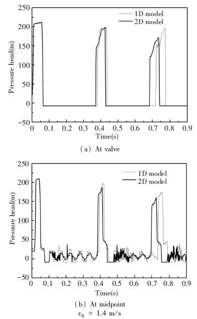
The proposed model is applied for analysis of water hammer flows with vapor cavity caused by the rapid downstream valve closure in a reservoir-pipe-valve system. The parameters of the numerical test are the following[2]: the pipe length is 37.23 m; the internal diameter of pipe is 22.1 mm; the pipe slope has a constant value of θ=3.2°; the wave speed is 1 319 m/s; the liquid density is 1 000 kg/m3; the upstream pressure head is 22.0 m; the vapor pressure head is -9.8 m; the weighting coefficient ψ is 1.0; the gas void fraction α is 10-7 at the standard condition; the valve closure time is 9 ms; the number of reaches in the axial direction Nx is 32; the number of reaches in the radial direction Nr is 90, and the weighting coefficients of both ε and θ are 1. Two cases of different initial mean velocities (v0= 0.3 m/s and v0=1.4 m/s) are used in the numerical test. Fig. 3 shows the comparison of the pressure heads at both the valve and the midpoint of the pipe calculated by both the 1D model and the proposed 2D model using the initial mean velocity of 0.30 m/s. In Fig. 3, as the computational time increased, the pressure heads obtained by the 2D model are correspondingly lower than those by the 1D model. Fig. 3 also shows that the rapid valve closure generates water hammer and subsequent vapor cavity (column separate) at the valve and the midpoint of the pipe. Both the 1D and 2D models correctly estimate that the peak pressures following the collapse of the vapor cavity exceed the Joukowsky pressure rise (av0/g). The first cavities at the valve for both the 1D and 2D models are generated at 0.065 3 s and then collapsed at 0.128 8 s; therefore the duration time of the first cavity is 0.063 5 s. For the experimental results of Bergant et al.[2], the first cavity at the valve is generated at 0.066 2 s and then collapsed at 0.129 8 s; therefore the duration time of the first cavity is 0.063 6 s. The comparison between the two models and the measurement shows that the generation, collapse, and duration times of the first cavity at the valve calculated by both 1D and 2D models are close to the experimental results[2]. However, the maximum pressure head of 98.6 m obtained by the 2D model is closer to the experimental value[2] of 95.6 m, comparing with the maximum pressure head of 101.5 m calculated by the 1D model.
Fig. 4 shows the traces of pressure heads at both the valve and the midpoint of pipe calculated by both the 1D and 2D models using the initial mean velocity of 1.4 m/s. The comparison shows that the pressure heads obtained by the 2D model are correspondingly lower than those by the 1D model as the computational time increases. The maximum pressure heads at the valve are almost equal to the water hammer head generated by the valve rapid closure at time 2L/a, which are 210 m for the 1D model and 212 m for the 2D model, respectively. The pressure heads following the collapse of the vapor cavity, obtained by both the 1D and 2D models, are lower than the Joukowsky pressure rise. In fact, the first pressure peaks following the collapse of the vapor cavity are 199.8 m for the 1D model and 198.5 m for the 2D model, respectively. The duration times of the first cavity at the valve are 0.311 8 s by the measurement, 0.312 2 s by the 1D model and 0.305 2 s by the 2D model, respectively.
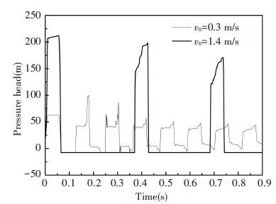
These duration times are much longer than the corresponding time 0.063 6 s and 0.063 5 s at the initial mean velocity of 0.30 m/s. Whether the first pressure peak following the collapse of the vapor cavity is lower than the Joukowsky pressure rise, it depends on the duration time of the first vapor cavity at the valve. Moreover, due to the energy dissipation, the pressure peaks in the water hammer flows are reduced as the computational time increases. Therefore, as the duration time of the vapor cavity increases, the pressure head following the collapse of the first cavity will be reduced. The duration time of the first cavity at the valve by the 2D model is shorter than the measurement. However, the maximum pressure heads following the collapse of the vapor cavity are closer to the measurement than the 1D model. Fig. 5 presents the comparison of both pressure heads at the valve calculated by the 2D model using the initial mean velocities of 0.3 m/s and 1.4 m/s.
In all numerical tests, the maximum pressure heads predicted by the 2D model are closer to the experimental results with respect to those obtained by the 1D model. The difference between both results is due to different physical descriptions for the wall shear stress. The results show that the quasi-2D model, taking into account the velocity profile in the cross section, predicts the maximum pressure heads of the two-phase water hammer flows more accurately than the 1D model.
4 Conclusions
A quasi-2D model for two-phase water hammer flows with vaporous cavity in pipeline systems is proposed in this paper. The model makes use of the quasi-2D model for pure liquid zone and the discrete vapor cavity model for vaporous cavity zone. The proposed model is applied for the numerical simulations of water hammer flows with vapor cavity caused by the rapid downstream valve closure in a reservoir-pipe-valve system. The results predicted by the proposed 2D model are compared with those of the 1D model using the same discrete vapor cavity model. The comparisons show that the maximum pressure heads calculated by the proposed model are closer to the experimental results than those by the 1D model.
Appendix
The explicit expressions for H and q can be derived from the following equation
|
$H_{i}^{n+1}-\theta {{C}_{qj}}q_{i, j-1}^{n+1}+\theta {{C}_{qj}}q_{i, j}^{n+1}={{K}_{i, j}}$
|
(29) |
where Ki, j= (Kpi, j+Kni, j)/2. Using that the radial flux on symmetry axis of a pipe is q=0 at j=1(r=0 or v=0) , q at j=2 from Eq.(29) is expressed by
|
$q_{i, 2}^{n+1}={{K}_{i, 2}}/\theta {{C}_{q2}}-H_{i}^{n+1}/\theta {{C}_{q2}}$
|
(30) |
Substituting again Eq.(30) into Eq.(29) , the radial flux q at j=3 is given by
|
$q_{i, 3}^{n+1}=\frac{{{K}_{i, 2}}}{\theta {{C}_{q2}}}+\frac{{{K}_{i, 3}}}{\theta {{C}_{q3}}}-\frac{H_{i}^{n+1}}{\theta {{C}_{q2}}}-\frac{H_{i}^{n+1}}{\theta {{C}_{q3}}}$
|
(31) |
In the same way, q at j=j is expressed as
|
$q_{i, j}^{n+1}=\sum\limits_{k=2}^{j}{\left( \frac{{{K}_{i, k}}}{\theta {{C}_{qk}}}-\frac{H_{i}^{n+1}}{\theta {{C}_{qk}}} \right)}$
|
(32) |
Since the radial flux q on the wall is q=0(v=0 at the wall), Eq.(32) at j=Nr+1 can be written as
|
$\sum\limits_{j=2}^{{{N}_{r}}+1}{\left( \frac{{{K}_{i, j}}}{\theta {{C}_{qj}}}-\frac{H_{i}^{n+1}}{\theta {{C}_{qj}}} \right)}=0$
|
(33) |
or
|
$H_{i}^{n+1}=\sum\limits_{j=2}^{{{N}_{r}}+1}{\frac{{{K}_{i, j}}}{\theta {{C}_{qj}}}}/\sum\limits_{j=2}^{{{N}_{r}}+1}{\frac{1}{{{C}_{qj}}}}=\sum\limits_{j=2}^{{{N}_{r}}+1}{\frac{{{K}_{pi, j}}+{{K}_{ni, j}}}{2{{C}_{qj}}}}/\sum\limits_{j=2}^{{{N}_{r}}+1}{\frac{1}{{{C}_{qj}}}}$
|
(34) |
Using the expressions of Cqj, Cu1j, Cu2j, and Cu3j, the other terms of Eq.(20) are written as follows:
|
$\sum\limits_{j=2}^{{{N}_{r}}+1}{\frac{1}{{{C}_{qj}}}}=\sum\limits_{j=2}^{{{N}_{r}}+1}{\frac{g}{{{a}^{2}}\Delta t}}{{r}_{cj}}\left( {{r}_{j}}-{{r}_{j-1}} \right)=\frac{g\tilde{A}}{2\pi {{a}^{2}}\Delta t}$
|
(35) |
|
$\begin{align}
& \sum\limits_{j=2}^{{{N}_{r}}+1}{\frac{{{K}_{pi, j}}}{{{C}_{qj}}}}=\sum\limits_{j=2}^{{{N}_{r}}+1}{\frac{g{{r}_{cj}}H_{i-1}^{n}\Delta {{r}_{j-1}}}{{{a}^{2}}\Delta t}}-\left( 1-\theta \right)\sum\limits_{j=2}^{{{N}_{r}}+1}{\Delta }q_{i-1, j}^{n}+ \\
& \sum\limits_{j=2}^{{{N}_{r}}+1}{\frac{{{r}_{cj}}u_{i-1, j}^{n}\Delta {{r}_{j-1}}}{a\Delta t}}+\frac{1-\varepsilon }{a}\times \\
& \sum\limits_{j=2}^{{{N}_{r}}+1}{\left( \frac{{{r}_{j}}{{v}_{Tj}}\Delta u_{i-1, j+1}^{n}}{\Delta {{r}_{cj+1}}}-\frac{{{r}_{j}}{{v}_{Tj-1}}\Delta u_{i-1, j}^{n}}{\Delta {{r}_{cj}}} \right)}= \\
& \frac{g\tilde{A}H_{i-1}^{n}}{2\pi {{a}^{2}}\Delta t}+\frac{\tilde{Q}_{i-1}^{n}}{2\pi a\Delta t}-\left( 1-\varepsilon \right)\frac{R\tau _{i+1, j}^{n}}{a\rho } \\
\end{align}$
|
(36) |
|
$\begin{align}
& \sum\limits_{j=2}^{{{N}_{r}}+1}{\frac{{{K}_{ni, j}}}{{{C}_{qj}}}}=\sum\limits_{j=2}^{{{N}_{r}}+1}{\frac{g{{r}_{cj}}H_{i+1}^{n}\Delta {{r}_{j-1}}}{{{a}^{2}}\Delta t}}-\left( 1-\theta \right)\sum\limits_{j=2}^{{{N}_{r}}+1}{\Delta }q_{i+1, j}^{n}- \\
& \sum\limits_{j=2}^{{{N}_{r}}+1}{\frac{{{r}_{cj}}u_{i+1, j}^{n}\Delta {{r}_{j-1}}}{a\Delta t}}-\frac{1-\varepsilon }{a}\times \\
& \sum\limits_{j=2}^{{{N}_{r}}+1}{\left( \frac{{{r}_{j}}{{v}_{Tj}}\Delta u_{i+1, j+1}^{n}}{\Delta {{r}_{cj+1}}}-\frac{{{r}_{j}}{{v}_{Tj-1}}\Delta u_{i+1, j}^{n}}{\Delta {{r}_{cj}}} \right)}= \\
& \frac{g\tilde{A}H_{i+1}^{n}}{2\pi {{a}^{2}}\Delta t}-\frac{\tilde{Q}_{i+1}^{n}}{2\pi a\Delta t}+\left( 1-\varepsilon \right)\frac{R\tau _{wi+1, j}^{n}}{a\rho } \\
\end{align}$
|
(37) |
with
|
$\begin{align}
& \tilde{A}=\sum\limits_{j=2}^{{{N}_{r}}+1}{2}\pi {{r}_{cj}}\Delta {{r}_{j-1}}, \tilde{Q}_{i}^{n}=\sum\limits_{j=2}^{{{N}_{r}}+1}{2}\pi {{r}_{cj}}\Delta {{r}_{j-1}}, \\
& \Delta q_{i, j}^{n}=q_{i, j}^{n}-q_{i, j-1}^{n}, \Delta u_{i, j}^{n}=u_{i, j}^{n}-u_{i, j-1}^{n} \\
\end{align}$
|
|
$\begin{align}
& H_{i}^{n+1}=\frac{1}{2}\left( H_{i-1}^{n}H_{i+1}^{n} \right)+\frac{a}{2g\tilde{A}}\left( \tilde{Q}_{i-1}^{n}-\tilde{Q}_{i+1}^{n} \right)- \\
& \left( 1-\varepsilon \right)\frac{a\Delta t\pi D}{2g\tilde{A}}\left( \tau _{wi-1}^{n}-\tau _{wi+1}^{n} \right) \\
\end{align}$
|
(38) |
If Nr is enough large, Eq.(38) leads to the following explicit equation
|
$\begin{align}
& H_{i}^{n+1}=\frac{1}{2}\left( H_{i-1}^{n}H_{i+1}^{n} \right)+\frac{a}{2gA}\left( Q_{w-1}^{n}-Q_{i+1}^{n} \right)- \\
& \left( 1-\varepsilon \right)\frac{a\Delta t\pi D}{2\rho gA}\left( \tau _{wi-1}^{n}-\tau _{wi+1}^{n} \right) \\
\end{align}$
|
(39) |
with
|
$\begin{align}
& \underset{{{N}_{r}}\to \infty }{\mathop{\lim }}\, \left( \sum\limits_{j=2}^{{{N}_{r}}+1}{2}\pi {{r}_{cj}}\Delta {{r}_{cj-1}} \right)=\int\limits_{0}^{R}{\pi ru\text{d}r}=A \\
& \underset{{{N}_{r}}\to \infty }{\mathop{\lim }}\, \left( \sum\limits_{j=2}^{{{N}_{r}}+1}{2}\pi {{r}_{cj}}u_{i, j}^{n}\Delta {{r}_{cj-1}} \right)=\left( \int\limits_{0}^{R}{\pi ru\text{d}r} \right)_{i}^{n}=Q_{i}^{n} \\
\end{align}$
|
Eq.(39) is identical to the equation derived from the discretized forms of 1D characteristic Eq.(6) .


 0)
0)
 0)
0)
 0)
0)
 0)
0)
 0)
0)
 0)
0)
 0)
0)
 0)
0)
 0)
0)
 0)
0)
 0)
0)
 0)
0)
 0)
0)
 0)
0)
 0)
0)
 0)
0)
 0)
0)
 0)
0)
 0)
0)
 0)
0)
 2016, Vol. 23


