2. Ministry of Science Research, Naval University of Engineering, Wuhan 430033, China
Underwater platform (such as submarine) usually discharges its vehicle through the launching tube of torpedo launching equipment[1]. This approach not only makes occupation of the torpedo launching tubes, but also should meet the requirement that the diameter and length of the vehicle matches the size of the launching tube. In response to this situation, this paper proposes the broadside discharging scheme, which can be used in underwater platforms to discharge large-caliber vehicle with negative buoyancy from the broadside. Underwater objects motion simulation can help evaluate the feasibility of this scheme. Many scholars have conducted research on modeling and simulation of underwater vehicle such as UUV[2-9], Underwater Glider[10-14], manned submarine vehicle[15]and so on. Some scholars study on the simulation analysis of underwater motion process of submarine launched missile and carrier[16-18]. But no studies have conducted the simulation of the non-powered vehicle discharged from the broadside of the submarine. Therefore, the mathematical model of non-powered vehicle discharged from the broadside is established and simulation is conducted in this paper, and the key parameters affecting the discharging process are analyzed quantitatively, the simulation results are used to analyze and verify the feasibility of this scheme.
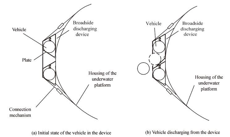
2 Broadside Discharging SchemeThe main part is the broadside discharging device, which can be placed at both sides of the underwater platform (for example, it can be placed between the pressure housing and the non-pressure housing of submarine), and can be also hung to the underwater platform as a separate component (see Fig. 1(a)).
|
Figure 1 Schematic diagram of the broadside discharging device |
The discharging process is as follows: firstly, the plate of the store box is opened, and then the vehicle rolls downward along the slope formed by the plate with the help of its own negative buoyancy (see Fig. 1(b)).
After the vehicle departs from the slope and a period of delay, the inflation valve of the air chamber in the vehicle is opened, and then the air cylinder starts to inflate the air chamber.When buoyancy is formed, the vehicle starts to turn from the horizontal direction to the vertical direction (water surface) and move upward until it reaches the surface.
3 Modeling of the Discharging Process 3.1 Modeling AssumptionsThe following assumptions are made during modeling:
(1) The impact of underwater current is not considered during the entire discharging process.
(2) The chamber inflation process is assumed to be an ideal adiabatic process.
(3) During the period in which the vehicle floats upward, the volume of the air chamber remains unchanged when it is inflated to a preset volume.
3.2 Establishment of Motion Coordinate SystemThe time when the vehicle starts moving on the plate is assumed as the initial moment. As shown in Fig. 2, the coordinate system is established on the vehicle, and the centroid of the vehicle is treated as the origin o.

|
Figure 2 Schematic diagram of the coordinate system |
The coordinate line starting from the origin to the horizontal direction is assumed as the x-axis (positive—rolling direction); the one pointing to the water surface vertically is the y-axis (positive—pointing to the water surface); and the one which is perpendicular to the xoy-plane and satisfies the right hand rule is the z-axis.
3.3 Establishment of the Vehicle Motion ModelThe motion of the vehicle after discharging can be divided into three stages—rolling on the plate, moving freely in seawater after leaving the plate and before opening the air chamber as well as the movement after opening the air chamber. The corresponding mathematical models are as follows:
(1) Model of the vehicle rolling on the plate.
Based on force analysis of the vehicle on the plate (see Fig. 2), the following rolling model of the vehicle on the plate can be established:
| $\frac{\text{d}{{v}_{x}}}{\text{d}t}=\frac{\left[ B\sin \beta -{{F}_{\text{mg}}} \right]\cos \beta -{{F}_{rx}}}{m}$ | (1) |
| $\frac{\text{d}{{v}_{y}}}{\text{d}t}=-\frac{\left[ B\sin \beta -{{F}_{\text{mg}}} \right]\sin \beta -{{F}_{ry}}}{m}$ | (2) |
| $\frac{\text{d}{{v}_{y}}}{\text{d}t}=\left\{ \begin{matrix} 0, & {{F}_{mz}}\ge {{F}_{rz}} \\ \frac{{{F}_{mz}}-{{F}_{rz}}}{m}, & {{F}_{mz}} <{{F}_{rz}} \\ \end{matrix} \right.$ | (3) |
where B=G-FB is the negative buoyancy; G is the gravity and FB is the buoyancy; m is its quality; vx, vy and vz are the components of the velocity of the vehicle′s centroid corresponding to the coordinate axis, respectively; Fmg=FN·μ1 is the rolling friction force on the plate, where μ1is the rolling friction coefficient and FN=B cos β is the bearing counter-force applied by the plate; β is the angle between the plate and the horizontal plane; Fmz=FN·μ2 is the sliding friction in z-axis; μ2 is the sliding friction coefficient; Frx, Fry and Frz are the seawater drag force in x-axis,y-axis and z-axis, respectively. Let i represent x, y and z, we get
(2) Model of the vehicle moving freely in seawater.
After the vehicle departs from the plate and before the air chamber works, the model of the vehicle moving freely in seawater is
| $\frac{\text{d}{{v}_{x}}}{\text{d}t}=-\frac{{{F}_{rx}}}{m}$ | (4) |
| $\frac{\text{d}{{v}_{y}}}{\text{d}t}=-\frac{B-{{F}_{ry}}}{m}$ | (5) |
| $\frac{\text{d}{{v}_{z}}}{\text{d}t}=-\frac{-{{F}_{rz}}}{m}$ | (6) |
(3) Model of the vehicle after the air chamber works.
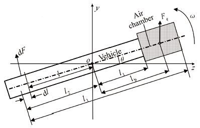
After a period of delay, the air chamber is opened, buoyancy is formed around the vehicle's head part. At this time, the vehicle's motion includes centroid motion and rotating around the centroid in zoy plane (see Fig. 3).
|
Figure 3 Schematic diagram of the vehicle rotating around the centroid |
The mathematical model corresponding to the centroid is
| $\frac{\text{d}{{v}_{x}}}{\text{d}t}=-\frac{-{{{{F}'}}_{rx}}}{m}$ | (7) |
| $\frac{\text{d}{{v}_{y}}}{\text{d}t}=-\frac{\left( G-{{F}_{B}} \right)-{{{{F}'}}_{ry}}-{{F}_{q}}}{m}$ | (8) |
| $\frac{\text{d}{{v}_{z}}}{\text{d}t}=\frac{-{{{{F}'}}_{rz}}}{m}$ | (9) |
where
The model of the vehicle rotating around the centroid is:
| $\frac{\text{d}\omega }{\text{d}t}=\left[ {{F}_{\text{b}}}{{l}_{\text{b}}}\cos \theta -sgn \left( \omega \right)\left( {{M}_{\text{s}}}+{{M}_{\text{q}}} \right) \right]/J$ | (10) |
where ω is the angular velocity of the vehicle axis rotating around the centroid; lb is the distance between the vehicle centroid and the buoyancy center of the air chamber; θ is the angle of the vehicle axis rotating around the centroid; sgn(ω) is the sign function; Ms is the torque generated by the vehicle's fluid drag force with respect to the its centroid; Mq is the torque generated by the air chamber's fluid drag force with respect to the vehicle's centroid. Based on the principle of calculus, the following models can be computed:
| ${{M}_{s}}=\sum\limits_{i=1}^{2}{\int_{0}^{{{l}_{i}}}{0.85{{c}_{tr}}}}\cdot \rho \cdot {{d}_{\text{T}}}\cdot {{\omega }^{2}}\cdot {{l}^{3}}\text{d}l$ | (11) |
| ${{M}_{\text{q}}}=\int_{{{l}_{1}}}^{{{l}_{c}}-{{l}_{1}}-{{l}_{2}}}{0.85{{c}_{tq}}}\cdot \rho \cdot {{d}_{\text{q}}}\cdot {{\omega }^{2}}\cdot {{l}^{3}}\text{d}l$ | (12) |
where ctr, ctq are the fluid drag coefficients when the vehicle rotates around the centroid; dT is the vehicle's diameter; dq is the equivalent diameter of the air chamber.
3.4 Inflation Model of the Air ChamberThe actual inflation process is complex. We commonly use the Control Volume method (CV method) or more precise Arbitrary Lagrangian-Eulerian method (ALE method) and Fluid-Solid Coupling method to simulate the inflation process[19-22]. Here we only need information about the volume change during the inflation process, so we made some simplifications about the inflation model. Based on the basic ideas of Control Volume method as well as thermodynamic theory and constitutive model of elastic body, we establish the one-dimensional mathematical model of the annular chamber inflation process of underwater vehicle. Given the fact that the actual inflation process takes very short time, for simplicity, we make the following assumptions: do not take the expansion of the folded portion of the air chamber (the process is very fast) into account; the stage when the air flows from the cylinder through the inflation valve to the air chamber is an adiabatic expansion throttling process, the air and water heat exchange loss inside the control body is ignored; the air pressure inside the chamber is uniform, the external seawater pressure of the chamber is the seawater pressure at the center of the chamber ring.
(1) State equation inside the air chamber.
Considering the interior of the chamber to be the control body, based on the assumptions above, the first law of thermodynamics can be used to depict the physical process inside the control body: The internal energy of the air inside the chamber is equal to: the internal energy of the initial air inside the chamber plus the enthalpy injected into the chamber through the inflation valve, minus the work done by the air inside the chamber to overcome the elastic force of the chamber, and minus the work done by the expanding chamber to overcome seawater drag force.
From the description above, the energye quilibrium equation corresponding to under water inflation process can be represented as:
| ${{U}_{q}}={{U}_{q0}}+{{H}_{i}}-{{H}_{o}}-{{W}_{q}}-{{W}_{h}}$ | (13) |
where Uq is the internal energy of the air inside the control body; Uq0is the internal energy of the initial air inside the control body; Hi is the enthalpy injected into the chamber through the inflation valve; Ho is the leakage enthalpy throughout the inflation process (if no leakage, Ho is zero); Wq is the work done by the air inside the chamber to overcome the elastic force of the chamber and Wh is the work done by the expanding chamber to overcome seawater drag force.
According to the energy conservation equation and the thermodynamic theorem, we can derive the gas state equation inside the air chamber:
| $\frac{\text{d}{{U}_{\text{q}}}}{\text{d}t}=\frac{\text{d}{{H}_{i}}}{\text{d}t}-\frac{\text{d}{{H}_{o}}}{\text{d}t}-\frac{\text{d}{{W}_{\text{q}}}}{\text{d}t}-\frac{\text{d}{{W}_{\text{h}}}}{\text{d}t}$ | (14) |
| $\frac{\text{d}{{T}_{\text{q}}}}{\text{d}t}=\frac{1}{{{c}_{v}}}\left( \frac{1}{{{m}_{\text{q}}}}\frac{\text{d}{{U}_{\text{q}}}}{\text{d}t}-\frac{{{U}_{\text{q}}}}{m_{\text{q}}^{2}}\frac{\text{d}{{m}_{\text{q}}}}{\text{d}t} \right)$ | (15) |
| $\frac{\text{d}{{p}_{\text{q}}}}{\text{d}t}=\left( \kappa -1 \right)\left( \frac{1}{{{V}_{\text{q}}}}\frac{\text{d}{{U}_{\text{q}}}}{\text{d}t}-\frac{{{U}_{\text{q}}}}{V_{\text{q}}^{2}}\frac{\text{d}{{V}_{\text{q}}}}{\text{d}t} \right)$ | (16) |
where Tq is the temperature of the air inside the chamber; mq is the mass of the air inside the control body; cV is the constant-volume specific heat of air and κ is the specific heat ratio of air (adiabatic index).
The enthalpy injection rate from cylinder to air chamber can be calculated as
| $\frac{\text{d}{{H}_{\text{i}}}}{\text{d}t}=-{{c}_{p}}{{T}_{\text{b}}}\frac{\text{d}{{m}_{\text{B}}}}{\text{d}t}$ | (17) |
where mB is the instantaneous mass of the air in the cylinder; TB is the thermodynamic temperature of the air in the cylinder and cp is the constant-pressure specific heat of air.
(2) Flow equation of air chamber inflation.
Assuming the mass flow of air that flows through the inflation valve into the air chamber is
| $\frac{\text{d}{{m}_{\text{B}}}}{\text{d}t}=-\frac{\text{d}{{m}_{\text{i}}}}{\text{d}t}$ | (18) |
The mass flow of air that flows through the inflation valve can be calculated as
| $\frac{\text{d}{{m}_{\text{i}}}}{\text{d}t}={{\varphi }_{\text{f}}}{{S}_{\text{v}}}{{\rho }_{\text{i}}}{{v}_{\text{ai}}}$ | (19) |
where φf is the air flow coefficient of the inflation valve; Sv=πdv2/4 is the flow area of the inflation valve, where dv is the diameter of the inflation valve; ρi is the flow density at the special-shaped hole; vai is the flow velocity of air flowing through the valve and ρi, and vai can be calculated according to Ref. [23].
(3) Model of the volume change rate of the air chamber.
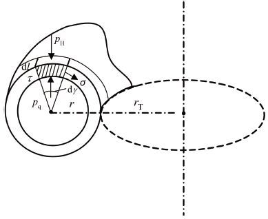
Considering the annular chamber infinitesimal (see Fig. 4), neglecting its bending stress we get the infinitesimal force equilibrium equation
|
Figure 4 Schematic diagram of the force of the chamber |
| $\sigma \tau \text{d}l\text{d}\gamma \text{=}\left( {{p}_{\text{q}}}-{{p}_{\text{H}}} \right)r\text{d}\gamma \text{d}l$ | (20) |
and then
| $\sigma =\left( {{p}_{\text{q}}}-{{p}_{\text{H}}} \right)r/\tau $ | (21) |
where pq is the air pressure inside the chamber; pH=ρhgH+p0 is the external seawater pressure of the chamber, where ρh is the seawater density; H is the seawater depth; p0 is the atmospheric pressure; r is the inner diameter of the annular chamber section; τ is thickness of the annular chamber; σ is the tensile stress resulted from the expansion of the chamber elastic material.
Considering the stress of the infinitesimal during the expansion of the chamber to be the stress generated by the uniaxial tensile infinitesimal, according to the Gauss theorem in the constitutive model of elastic body[24], we get
| $\sigma ={{C}_{\text{R}}}\left( \lambda -1/{{\lambda }^{2}} \right)$ | (22) |
where λ is the elongation of elastic material; CR is the initial shear elasticity modulus of rubber.
If the elongation of the infinitesimal is λ, and the volume of elastic body remains constant during expansion, then
| $r=\lambda {{r}_{0}}, \tau ={{\tau }_{0}}/\lambda $ | (23) |
where r0, τ0 are the inner diameter and thickness of the annular section before inflation, respectively. Substitute Eq. (23) into Eq. (22) , we get
| $\sigma =\left( {{p}_{\text{q}}}-{{p}_{\text{H}}} \right){{r}_{0}}{{\lambda }^{2}}/{{\tau }_{0}}$ | (24) |
Combining and differentiating Eqs. (21) and (24) , we get:
| $\frac{\text{d}\lambda }{\text{d}t}={{\chi }_{1}}\frac{\text{d}{{p}_{\text{q}}}}{\text{d}t}$ | (25) |
where:
The annular chamber volume model can be calculated as follows:
| ${{V}_{\text{q}}}=\pi {{r}^{2}}2\pi (r+{{r}_{\text{T}}})=2{{\pi }^{2}}r_{0}^{2}{{\lambda }^{2}}(\lambda {{r}_{0}}+{{r}_{\text{T}}})$ | (26) |
where rT is the inner diameter of the annular chamber (see Fig. 4).
Its volume change rate is
| $\frac{\text{d}{{V}_{q}}}{\text{d}t}={{\chi }_{2}}\frac{\text{d}\lambda }{\text{d}t}$ | (27) |
where χ2=6π2r03λ2+4π2r03λrT .
(4) Power equation of the air chamber to overcome the seawater pressure.
From the volume change rate, we can derive the power equation of the air chamber to overcome the seawater pressure
| $\frac{\text{d}{{W}_{\text{h}}}}{\text{d}t}=\left\{ \begin{matrix} 0, & {{p}_{\text{q}}}\le {{p}_{\text{H}}} \\ {{p}_{\text{H}}}\frac{\text{d}{{V}_{\text{q}}}}{\text{d}t}, & {{p}_{\text{q}}}>{{p}_{\text{H}}} \\ \end{matrix} \right.$ | (28) |
(5) Power equation of the air inside the chamber to overcome the elastic force of the chamber.
If the elongation of the elastic material infinitesimal is λ, then we can derive the work done by the air inside the chamber to overcome the elastic force of the chamber
| ${{W}_{\text{h}}}=2{{\pi }^{2}}r_{0}^{2}({{p}_{\text{q}}}-{{p}_{\text{H}}})\left[ {{\lambda }^{3}}{{r}_{0}}+{{\lambda }^{2}}({{r}_{\text{T}}}-{{r}_{0}})-\lambda {{r}_{\text{T}}} \right]$ | (29) |
Differentiating (26) , we get the power equation
| $\frac{\text{d}{{\text{W}}_{\text{q}}}}{\text{d}t}=\left\{ \begin{matrix} 0, & {{p}_{q}}\le {{p}_{H}} \\ \left( \frac{{{x}_{3}}}{{{x}_{1}}{{x}_{2}}}+\frac{{{x}_{4}}}{{{x}_{2}}} \right)\frac{\text{d}{{\text{V}}_{\text{q}}}}{\text{d}t}, & {{p}_{q}}>{{p}_{H}} \\ \end{matrix} \right.$ | (30) |
where
| $\begin{align} & {{x}_{3}}=2{{\pi }^{2}}r_{0}^{2}\left[ {{\lambda }^{3}}{{r}_{0}}+{{\lambda }^{2}}\left( {{r}_{T}}-{{r}_{0}} \right)-\lambda {{r}_{T}} \right] \\ & {{x}_{4}}=2{{\pi }^{2}}r_{0}^{2}\left( {{p}_{q}}-{{p}_{H}} \right)\left[ 3{{\lambda }^{2}}{{r}_{0}}+2\lambda \left( {{r}_{T}}-{{r}_{0}} \right)-{{r}_{T}} \right] \\ \end{align}$ |
(6) State equation of the air inside the cylinder.
Assuming the inflation process is an ideal adiabatic process, and then the state model of the air inside the cylinder is
| $\frac{\text{d}{{\text{p}}_{B}}}{\text{d}t}=k\cdot \frac{{{p}_{B}}}{{{m}_{B}}}\cdot \frac{\text{d}{{\text{m}}_{B}}}{\text{d}t}$ | (31) |
| $\frac{\text{d}{{\text{T}}_{B}}}{\text{d}t}=\left( k-1 \right)\cdot \frac{{{T}_{B}}}{{{m}_{B}}}\cdot \frac{\text{d}{{\text{m}}_{B}}}{\text{d}t}$ | (32) |
1) Vehicle parameters.
Discharging by gravity: diameter dt=800 mm; length Lt=10 m; negative buoyancy B=500 kg.
2) Chamber inflation related parameters.
Cylinder initial pressure pB0=12 MPa; cylinder volume VB0=140 L; largest diameter of chamber after inflation dq=2.0 m (inner diameter of the carriage diameter); valve diameter dv=20 mm; inflation delay time td=2.6 s (simulation starts at the time when the vehicle begins to roll on the slope).
3) Discharging environmental parameters.
Discharging depth H=100 m; underwater temperature T=15 ℃; seawater density ρs=1 020 kg/m3.
4) Other parameters.
Speed of the underwater platform when discharging the vehicle vsub=3 m/s; slope angle α=30°; slope length LX=1.5 m.
Air gas constant R=287.04 J/(kg·k);air adiabatic index κ= 1.4.
4.2 Simulation Results and Corresponding Analysis1) Simulation results with basic parameters.
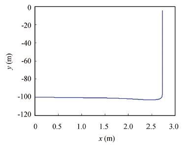
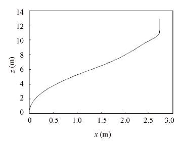
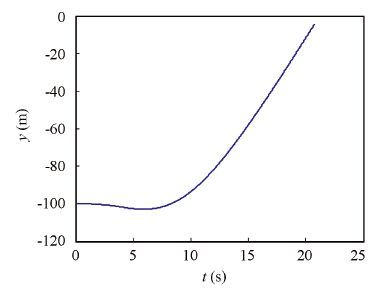
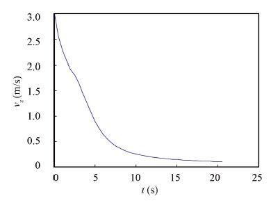
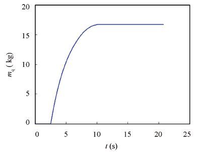
The simulation results with basic parameters show that, the vehicle with 500 kg negative buoyancy is discharged in 100 m depth and begins to float upward 2.7 m away from the submarine (see Figs. 5 and 6), imposing no influence on the safety of the submarine and vehicle. 20.7 s later after discharging, the vehicle surfaces (see Fig. 7), and the outlet velocity of the vehicle (especially y-axis direction, the same below) is about 9.7 m/s (see Fig. 8, the vehicle velocity in other direction see Figs. 9-10). In the course of the vehicle floating upward, it rotates from the horizontal to the vertical position; and the maximum swing angle of the vehicle in the vertical state is no more than 3.1° (see Fig. 11). The outlet speed and attitude of the vehicle meets the requirements of missile launching. In the course of the vehicle floating upward, the chamber was inflated with 16.7 kg air (see Fig. 12).
2) Simulation results with varying parameters.
Vehicle negative buoyancy and discharge depth will affect the process of the vehicle floating upward.
|
Figure 5 Vehicle trajectory in oxy plane |
|
Figure 6 Vehicle trajectory in oxz plane |
|
Figure 7 Vehicle displacement curve in y-axis direction |

|
Figure 8 Vehicle velocity curve in y-axis direction |

|
Figure 9 Vehicle velocity curve in x-axis direction |
|
Figure 10 Vehicle velocity curve in z-axis direction |

|
Figure 11 Vehicle rotation angle curve in the discharging process |
|
Figure 12 Mass change curve of the inflation chamber in the discharging process |
(1) Simulation results with the effects of negative buoyancy.
The simulation results with varying parameters show that, the negative buoyancy of the vehicle imposes great impacts on the security of its discharge and the floating process(see Fig. 13). As the vehicle is discharged by gravity, the larger the negative buoyancy of the vehicle is, the larger the speed (in x-axis direction) at which the vehicle departs from the submarine is (see Fig. 14), and the time it takes to leave the submarine is less, which is good for the discharge safety. But too large negative buoyancy is disadvantageous to the process of floating upward, for example, when the negative buoyancy decreases from 700 kg to 500 kg and 300 kg, the outlet time decreases from 28.9 s to 20.7 s and 17.9 s (Fig. 15), the outlet speed increases from 8.5 m/s to 9.7 m/s and 10.8 m/s (see Fig. 16), in that order. Changes in negative buoyancy have little influence on the swing angle of the vehicle after it surfaces the water, which is nearly 3°.
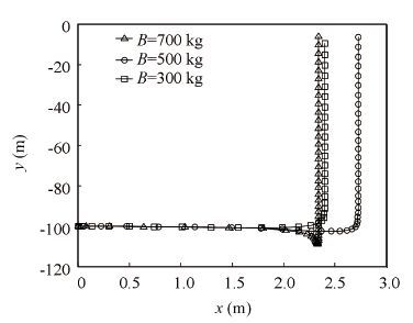
|
Figure 13 Vehicle trajectory in oxy plane |
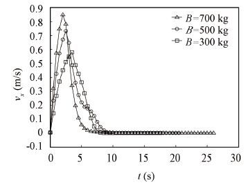
|
Figure 14 Vehicle velocity curve in x-axis direction |
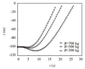
|
Figure 15 Vehicle displacement curve in y-axis direction |
(2) simulation results with the effects of discharge depth.
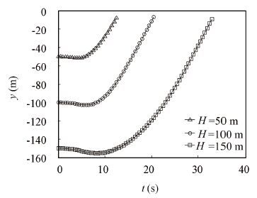
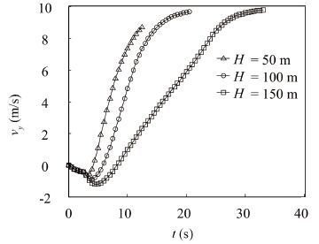
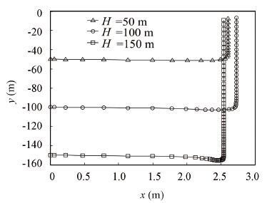
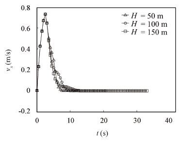
The effect of the vehicle discharge depth on floating time is obvious. The discharge depth increases, so does the floating time, and they are in proportional relationship. When the discharge depth increases from 50 m to 150 m, the floating time increases from 12.9 s to 33.4 s (see Fig. 17). The discharge depth slightly affects the outlet speed, great changes in discharge depth results in small changes in outlet speed.When the discharge depth increases from 50 m to 150 m, the outlet speed increases from 8.82 m/s to 9.78 m/s (see Fig. 18). Discharge depth slightly affects the distance between the vehicle and the submarine(see Fig. 19) as well as the swing angle of the vehicle and the vehicle velocity x direction(see Fig. 20).
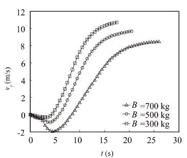
|
Figure 16 Vehicle velocity curve in y-axis direction |
|
Figure 17 Vehicle displacement curve in y-axis direction |
|
Figure 18 Vehicle velocity curve in y-axis direction |
In addition to the two parameters above, the initial pressure of the air cylinder, the diameter of the valve and the delay time to open the valve etc., have certain influence on the process of the vehicle floating upward, which are not discussed here.
|
Figure 19 Vehicle trajectory in oxy plane |
|
Figure 20 Vehicle velocity curve in x-axis direction |
5 Conclusions
Based on the mathematical model of vehicle discharged from the broadside and related simulations, this paper gives insight into the motion of the non-powered large-scale vehicle floating upward after being discharged from the broadside of underwater platform by gravity. Simulation results show that the proposed scheme is feasible. The models and simulation results can be used in further demonstration on the broadside discharging technology of the underwater platform.
| [1] |
Wang Shuzong, Wang Yizhong.
Conspectus of Naval Shipborne Weapon Equipment. Beijing: Weapon Industry Press, 1995 .
( 0) 0)
|
| [2] |
Du Xiaoxu, Song Baowei, Cao Yonghui. Study on 6-DOF motion aimulation of long range UUV with several loads.
Proceeding of the Fouth National Conference on Marine and Marine Engineering,2009 : 267-270.
( 0) 0)
|
| [3] |
Zhang Bin, Song Baowei, Zhu Xinyao, et al. Modeling and simulation of unmanned underwater vehicle parking on seabed.
Acta Armamentarii,2014, 35 (4) : 572-576.
( 0) 0)
|
| [4] |
Ding Hao, Song Baowei, Wen Zaiding, et al. Conceptual design and study of flapping-foil and gliding UUV.
Journal of Machine Design,2012, 29 (3) : 36-40.
( 0) 0)
|
| [5] |
Song Baowei, Chen Liangjun, Ding Hao, et al. Design and kinematics simulation of UUV’s flapping wing.
Journal of Machine Design,2011, 28 (4) : 36-39.
( 0) 0)
|
| [6] |
Xu Feng, Chen Qing, Zou Zaojian, et al. Modeling of underwater vehicles’ maneuvering motion by using integral sample structure for identification.
Journal of Ship Mechanics,2014, 18 (3) : 211-220.
( 0) 0)
|
| [7] |
Xu Guozhuo.Research on Path Following Control for Muli-UUV Formation.Harbin:Harbin Engineering University, 2012.
( 0) 0)
|
| [8] |
Yang Zhidong, Pan Guang, Du Xiaoxu. Longitudinal motion modeling and simulation of tethered AUV with length-variable towing cable.
Torpedo Technology,2014, 22 (1) : 14-19.
( 0) 0)
|
| [9] |
Wang B, Su Y M, Xu Y R, et al. Modeling and motion control system research of a mini underwater vehicle.
Sixth International Symposium on Underwater Technology,2009 : 71-75.
( 0) 0)
|
| [10] |
Sun Xiujun. Dynamic Modeling and Motion Control for a Hybrid-driven Underwater Glider.Tianjin:Tianjin University, 2015.
( 0) 0)
|
| [11] |
Wang Y H, Wang S X. Dynamic modeling and three-dimensional motion analysis of underwater gliders.
China Ocean Engineering,2009, 23 (3) : 489-504.
( 0) 0)
|
| [12] |
Mahmoudian N, Geisbert J, Woolsey C. Dynamics & control of underwater gliders unsteady motions. Virginia Center for Autonomous Systems, 2009.1-37 .(Report No. VaCAS-2007-01)
( 0) 0)
|
| [13] |
Gao Ying, Ma Xiaohui, Jiang Tao, et al. Design and hydrodynamic simulate of underwater glider model.
Foreign Electronic Measurement Technology,2011, 30 (11) : 74-78.
( 0) 0)
|
| [14] |
Li Wuqiang, Hu Yuli, Zhong Ruyi. Motion analysis and trajectory simulation of site controllable underwater glider.
Computer Simulation,2013, 30 (7) : 331-336.
( 0) 0)
|
| [15] |
Xie B, Xu J Y, Zhang H, et al. Dynamic modeling and investigation of maneuver characteristics of a deep-sea manned submarine vehicle. China Ocean Engineering, 23(3):505-516.
( 0) 0)
|
| [16] |
Cui Naigang, Cao Chunquan, Wei Changzhu. Mechanics simulation analysis of underwater motion process of submarine launched missile.
Journal of Ballistics,2009, 21 (2) : 95-99.
( 0) 0)
|
| [17] |
Hou Erhu, Zhang Yuwen, Cai Fan, et al. Simulation of underwater motion of tail separation section submarine-launched missile carrier.
Computer Simulation,2012, 29 (8) : 31-34.
( 0) 0)
|
| [18] |
Zhang Jinchun, Wang Xingping, Han Qinglong, et al. Study of launching underwater-to-air missile using unpowered underwater vehicle without fins and rudders.
Tactical Missile Technology,2014 (4) : 26-31.
( 0) 0)
|
| [19] |
Zhong Zhihua, Yang Jikuang. Automotive airchamber technology and its application.
China Mechanical Engineering,2002, 11 (2) : 234-238.
( 0) 0)
|
| [20] |
Wen Jinpeng, Li Bin, Yang Zhichun. Progress of study on impact attenuation capability of airchamber cushion system.
Journal of Astronautics,2010 : 2338-1445.
( 0) 0)
|
| [21] |
Zhao Qiuyan. Inflatable airbag landing system of mars pathfinder.
Space Recovery & Remote Sensing,2001, 22 (4) : 6-12.
( 0) 0)
|
| [22] |
Deng Chunyan, Pei Jinhua. Simulation about buffer process of omni-directional-type airbag landing device.
Chinese Space Science and Technology,2010, 2 (1) : 78-83.
( 0) 0)
|
| [23] |
Lian Yongqing, Wang Yizhong. Principle of Torpedo Launcher.
Beijing:National Defence Industry Press,2012 : 196-197.
( 0) 0)
|
| [24] |
Luo Wenbo, Tan Jianghua. A hybrid hyperelastic constitutive model of rubber materials.
Chinese Journal of Solid Mechanics,2008, 29 (3) : 277-281.
( 0) 0)
|
 2016, Vol. 23


