2. Xi'an Communications Institute, Xi'an 710065, China
In 1971, O ′ Keefe and Dostrovsky found place cells in the rat hippocampus [1]. Place cells are corresponding to the spatial location, and the environment can be represented by the whole place cells. The found of place cells shows that there is a cognitive map inside the animal brain. However, place cells just indicate the isolated points in the cognitive map, so they are not enough for rat to navigate by its own motion. In 2005, Hafting et al.[2] found some neurons in rat entorhinal cortex. These neurons behave regularly hexagonal firing pattern, and they are called as grid cells. The firing of grid cells is related to the animal motion, and their regular firing pattern shows that grid cells can be used for space transformation [3].Similar to place cells and grid cells, the found of head direction cells and border cells also reveal some special functions that support the animal navigation[4-5].
The outcome of the study of animal brain is gradually focused on by the navigation researchers who hope that the navigation mechanism of animal can be used in the vehicle navigation[6-8], so the vehicle can finally behave bionic information processing similar to animal brain during its navigation. To realize it, the first question that should be solved is the simulation of the cells' firing. In this paper, the generation of the firing pattern of grid cells is discussed.
Currently, there are three kinds of grid cells models, including independent neuron models based on oscillatory interference [9-11], recurrent network models based on continuous attractor dynamics[12-13] and model based on column structure model [14-16]. Oscillatory interference models use interference patterns generated by multiple membrane-potential oscillations to explain grid formation. The instantaneous frequencies of the oscillators are determined by the running speed and running direction of the animal such that a spatial rather than temporal firing pattern is generated. The clearest strength of the oscillatory interference models is that the experimental predictions are relatively easy to test, and the predictions from the oscillatory interference models have provided opportunities for experimental data to refute or support the original suggestions[3].The shortages of these models are that they regard biological oscillators as perfect sinusoids, and they may generate repeating fields, which have not been observed at that time. For attractor network models, they use activity in local networks with specific connectivity to generate the grid pattern. The activity patterns are moved across a network of recurrently connected, and firing patterns emerge by path integration of speed and direction signals. These models have been widely used to simulate the firing of grid cells, and they can avoid the edge effects by supposing that neurons at the edges of the network connect with neurons on the opposite edges. One major limitation of the original attractor models for grid cell formation is the lack of temporal dynamics that can contribute to phase precession in grid cells. For column structure model, the idea of this model is similar to the oscillatory interference models, but it is realized by modulus operation. This model can be easily understood, and the firing pattern of grid cells is generated by pure numerical calculation. Besides, the process of column structure model is convenient to operate.
Different grid cells models have different computational process, but what we should consider when we design them? We think that two parts should be paid attention to. One is how the integrate information produced by speed and direction is associated with the space grid. The other one is how to build the relation between the firing rate of grid cells and the integrate information. For the pure mathematical calculation, column structure model is simpler and behaves better maneuverable. So this paper mainly focuses on column structure model. Through the study, we find that the relation between the gird spacing and the base of modulo operator is not considered in this model and the firing rate in the firing field is a constant which is different from the firing pattern of biological grid cells. Therefore, in this paper, column structure model is improved and deepened. The result can lay a foundation to the farther study, such as the metric of spatial distance through the firing of grid cells, path integration based on grid pattern, the transformation of grid cell inputs to place field, and so on.
2 Firing Pattern of Grid CellsIn 2005, Hafting et al.[2] pointed out that some neurons in rat entorhinal cortex have spatial firing characteristics, and they are called as grid cells. Grid cells behave regularly hexagonal firing pattern. They are activated whenever the animal is located in any vertex of the regular hexagon. Subsequently, the discoveries about grid cells are confirmed and extended by the team of Moser E I and Moser M B[2, 3, 17-19]. The scholars in London University also point out the existence of the human grid cells[20].
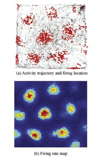
Fig. 1 shows the firing pattern of a single grid cell in biological experiment[3].The gray line is the trajectory of the rat, and each spike is plotted in red (Fig. 1(a)). Firing rate map is color encoded (Dark blue expresses minimum rate. Dark red expresses maximum rate) (Fig. 1(b)). Usually, the firing pattern is described by four parameters, including grid spacing, orientation, phase and firing field. The grid spacing is the distance between two vertexes. The orientation is expressed as the angle between a camera-defined reference line (0 degrees) and a vector to the nearest vertex of the inner hexagon in the counterclockwise direction.The phase is the spatial shift. The firing field is the area with grid cell firing.The firing characteristics of grid cells are summarized as follows:
|
Figure 1 iring pattern of grid cell in biology experiment[3] |
1) Neighboring grid cells share a common orientation and spacing, but their vertex locations are different. Besides, the firing pattern of the same grid cell change with the changing of activity area.
2) The grid spacing and the size of individual firing field increase from dorsal to ventral dMEC(dorsal medial entorhinal cortex).
3) For the different experiments, the firing pattern is stable in the same scene, and it rotates with the rotation of external cues. However, the grid spacing and the size of firing field are unchangeable.
4) The firing pattern is anchored to external cues, but it persists in their absence.
The regular firing pattern of grid cells shows that grid cells are directly related to space transformation. As a result, the researchers are always exploring the computational model to simulate grid cells, and they hope the navigation mechanism based on grid cells can be applied in vehicle navigation in the near future.
3 Improved Computational ModelCurrently, the input information of grid cells model is mostly from head direction cells, and the firing rate of head direction cells is decided by moving speed, direction and its preferred direction. When the speed and direction information is received by the sensor, the periodic function or structure are usually adopted to deal with the perceived information in the computational models, and the processing result is associated with the firing rate of grid cells. The computational model discussed in this paper has the similar process.
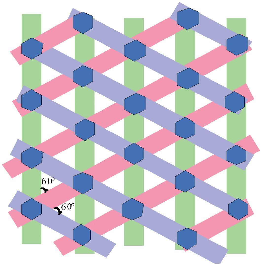
The main idea of the grid cells model based on column structure is that [14-16]: the vehicle perceives the speed and direction through the sensor, then the perceived information is processed by multiple direction systems with different preferred directions (the angle between the adjacent direction systems is π/6). As a result, the displacement along the preferred direction is obtained, and then modulus operation is used to process the displacement to get the remainder. Based on the setting regular intervals, the obtained remainder is corresponding to different status, including 1 and 0. Different status in the space can form column structure, and the integration of multiple column structures can generate equilateral hexagon. Schematic of this computational model is shown in Fig. 2. The column with the same color is corresponding to the same direction system. The grid nods expressed by dark blue are formed by the combination of different columns.
|
Figure 2 Schematic of computational model of grid cells based on column structure |
From the analysis of firing pattern of biological grid cells, we get that the firing rate in the firing field is not a constant. Contrarily, it is regular, as shown in Fig. 1(b). However, the firing rate in the firing field calculated by the column structure model is always 1, which is different from the biological grid cells. Therefore, the column structure mode is improved here.
Which way can be used to build the relation between the location and the firing rate? O ′ Keefe et al. adopt Gaussian-like function to describe the relation between the firing rate of place cell and the location[21]. The formula is as follows:
| $$g\left( p \right) = \exp - \left( { - \frac{{{{\left\| {p - l} \right\|}^2}}}{{2\sigma _{pc}^2}}} \right)$$ | (1) |
where l is the reference position of place cell. σpc2 is the adjustment factor of firing rate. Fig. 3 shows the simulation of the firing of place cell. The space area is 100 cm×100 cm. l is(50,50).σpc2is 40. Compared with the results in Fig. 1(b), the firing pattern is similar to a single grid nod. So the Gaussian-like function can provide an approach to encode the firing rate of grid cells.

|
Figure 3 Simulation of the firing of place cell |
The calculation process of improved computational model of grid cells based column structure is shown below.
Step 1:Construct the head direction cells.
Let N(3≤N≤6)be the number of head direction cells, and the preferred direction of head direction cell i is denoted by di(expressed by two-dimensional,i=1,2,…,N). The angle between the adjacent di is π/6.
Step 2:Calculate the displacement along the preferred direction.
During vehicle running, the speed and direction information are projected to the preferred directions of head direction cells. As a result, at each positioning moment, the relative displacements from the starting point along the different preferred directions are obtained. The result is denoted by Li. The calculation formula is as follows:
| $${L_i}\left( t \right) = \smallint _0^tv\left( t \right) \cdot {d_i}dt$$ | (2) |
where v(t) is the vehicle speed. If the vehicle runs in plane,v(t) is two-dimensional vector,“·” is vector dot multiplication.
Step 3:Process the displacement to get the remainder by modulus operation.
Let A be the grid spacing of firing pattern that need to be generated. Let B be the base of modulus operation. Then, the displacements obtained in Step 2 are processed by modulus operation, and the remainder is denoted by Si(t).
| $${S_i}\left( t \right) = \bmod \left( {{L_i}\left( t \right), B} \right)$$ | (3) |
Therefore, at each positioning moment, the displacements will be transformed into the range of (0, B). In this step, the relation between A and B is as follows:
| $$B = A\cos \left( {\frac{\pi }{6}} \right)$$ | (4) |
The reason for the existence of the proportion cos(π/6)is that: A represents the distance between two vertexes, but B represents the distance between the two adjacent column structures. Fig. 6 shows their relation. The angle between A and B is π/6, and it is not considered in the original model.
|
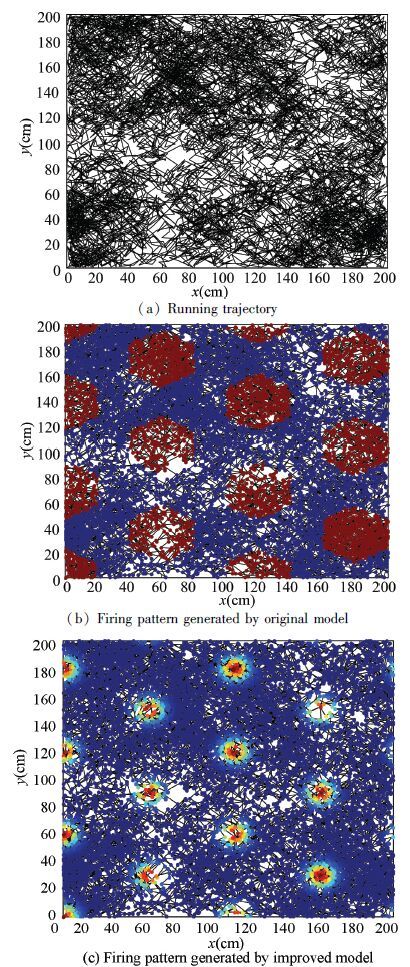
Figure 6 Firing results of a grid cell during running |
Step 4:The remainder is encoded by Gaussian-like function, and the result is denoted by f.
Let r be the firing field radius. Let fi be the encoding output along the preferred direction of head direction cell i. fi is calculated by the following formula:
| ${{f}_{i}}\left( t \right)=\left\{ \begin{align} & \begin{matrix} \exp \left( -\frac{s_{i}^{2}\left( t \right)}{2\sigma _{i}^{2}} \right), & 0\le {{S}_{i}}\left( t \right)\le r \\ \end{matrix} \\ & \begin{matrix} 0, & r<{{S}_{i}}\left( t \right)<B-r \\ \end{matrix} \\ & \begin{matrix} \exp \left[ --\frac{{{\left( s_{i}^{2}\left( t \right)-B \right)}^{2}}}{2\sigma _{i}^{2}} \right], & B-r{{S}_{i}}\left( t \right)\le B \\ \end{matrix} \\ \end{align} \right.$ | (5) |
where σi2 is the adjustment factor of firing rate along the preferred direction of head direction cell i.

|
Figure 4 Schematic of the relation between A and B |
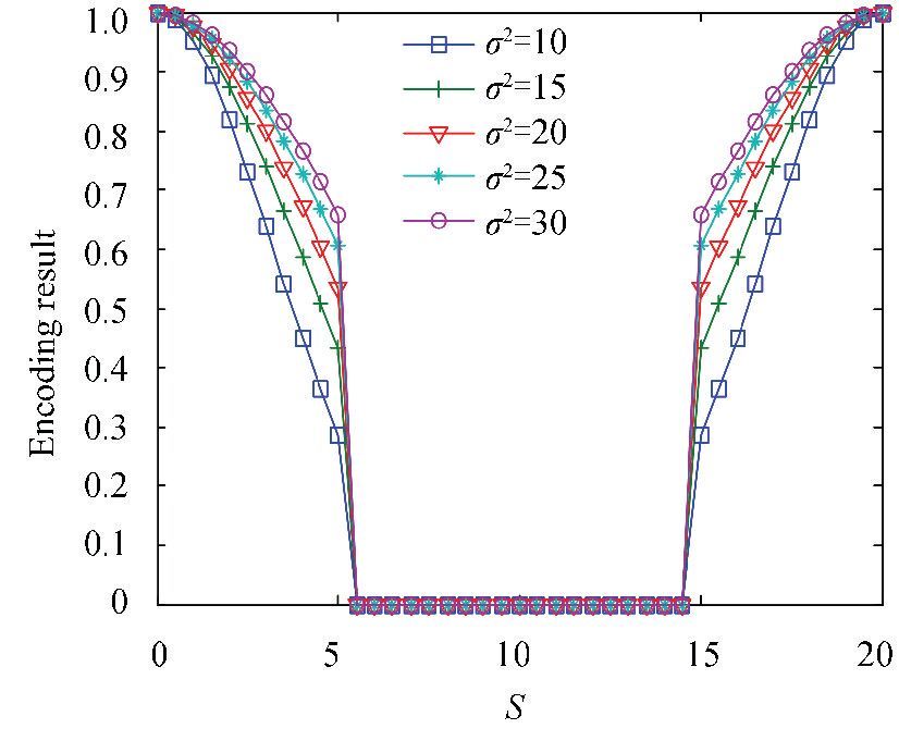
Fig. 5 shows the encoding result with the change of the change of σ2(B is set to 20. r is set to 5). Obviously, the encoding result for the same remainder (S) increases with the increase of σ2. I.e.,σ2 decides the variety trends of encoding results, which directly affects the firing of grid cells. It will be discussed in the following section.
|
Figure 5 Encoding result with the change of σ2 |
Step 5: The encoding results along different preferred directions of head direction cells are integrated. Then the firing rate of grid cell is got, denoted by fGC. The formula is as follows:
| $${f_{GC}}\left( t \right) = \prod\limits_{i = 1}^N {{f_i}\left( t \right)} $$ | (6) |
Through the above five steps, at each location, the firing rate of grid cell is obtained, and the firing pattern similar to the biological characteristics can be generated during the vehicle running. Besides, the firing pattern can be changed by adjusting the model parameters. In next section we will discuss the realization and the operability of this improved computational model of grid cells.
4 Results and Analysis 4.1 Realization of Improved Computational ModelAs mentioned in Section 2, the firing pattern of biological grid cells is mainly described by grid spacing, orientation, phase and firing field, and the firing pattern in the same environment is stable even though the activity area is extended. Besides, for different grid cells, the firing patterns are diverse. Therefore, this section mainly analyzes whether the firing pattern generated by the improved computational model can keep consistent with the biological characteristics. In the simulation, some hypotheses are made as follows:
1) The vehicle leaves from the origin of reference frame, and it runs in the plane with rectangle shape.
2) The positioning of the vehicle is implemented by discrete manner, and there is no positioning error.
3) The speed is a constant in a positioning cycle, and it changes randomly in different positioning cycles. After enough positioning times, the vehicle can traverse enough regions.
4) The direction of the speed is changed when the vehicle arrives at the boundary, and the relation between the new direction and the original direction obeys the reflection theorem.
Simulation parameters are set according to Table 1.The vehicle runs in the plane, and 10 000 positioning times are carried out during the running. At each location, the firing rate of grid cell is calculated by the original model and our improved model. Fig. 6 shows the firing results of a grid cell during vehicle running. Firing rate map is color coded (Dark blue expresses minimum firing rate and dark red expresses maximum firing rate). The black lines in Fig. 6(a) express the running trajectory. Firing pattern generated by the original model and improved model are respectively shown in Figs. 6(b) and 6(c). Obviously, the firing pattern generated by original model shows that the firing rate in the firing field is unchangeable. However, the improved computational model can generate the regular hexagonal grid, and the firing rates in the firing field are encoded. In the central, the firing rate is high, and it is low in the edge. Simultaneously, we can find that the grid spacing obtained by the original model is different from the grid spacing defined by the biological grid cell, but the improved model avoids it well. Therefore, the firing pattern generated by the improved computational model is more consistent with biological characteristic than original model.
| Table 1 Simulation parameters |
In the following section, we will discuss the change of firing pattern by adjusting the model parameters in Table 1, so the diversity of the firing pattern of different grid cells can be simulated.
Fig. 7 shows the firing pattern when the running area is extended.The positioning time is 35 000, and the new running area is 350 cm×350 cm. Compared with the results in Fig. 6(c), the grid spacing, orientation, and the size of firing field remain unchanged.Besides, the firing pattern is same in the corresponding area, but the nod number increases with the expansion of the area.Obviously, the improved model can simulate the characteristic of grid cell in the expansion area well.

|
Figure 7 Firing pattern after extending the running area |
Fig. 8 shows the firing pattern when the preferred directions of head direction cells are changed. The positioning time is 20 000, and the new d1-d6 are respectively set to 20°,80°,140°,200°,260° and 320°. Compared with the Fig. 6(c), the orientation of the firing pattern is changed, i.e., the computational model can generate the firing pattern with different orientation.

|
Figure 8 Firing pattern after changing the preferred directions of head direction cells |
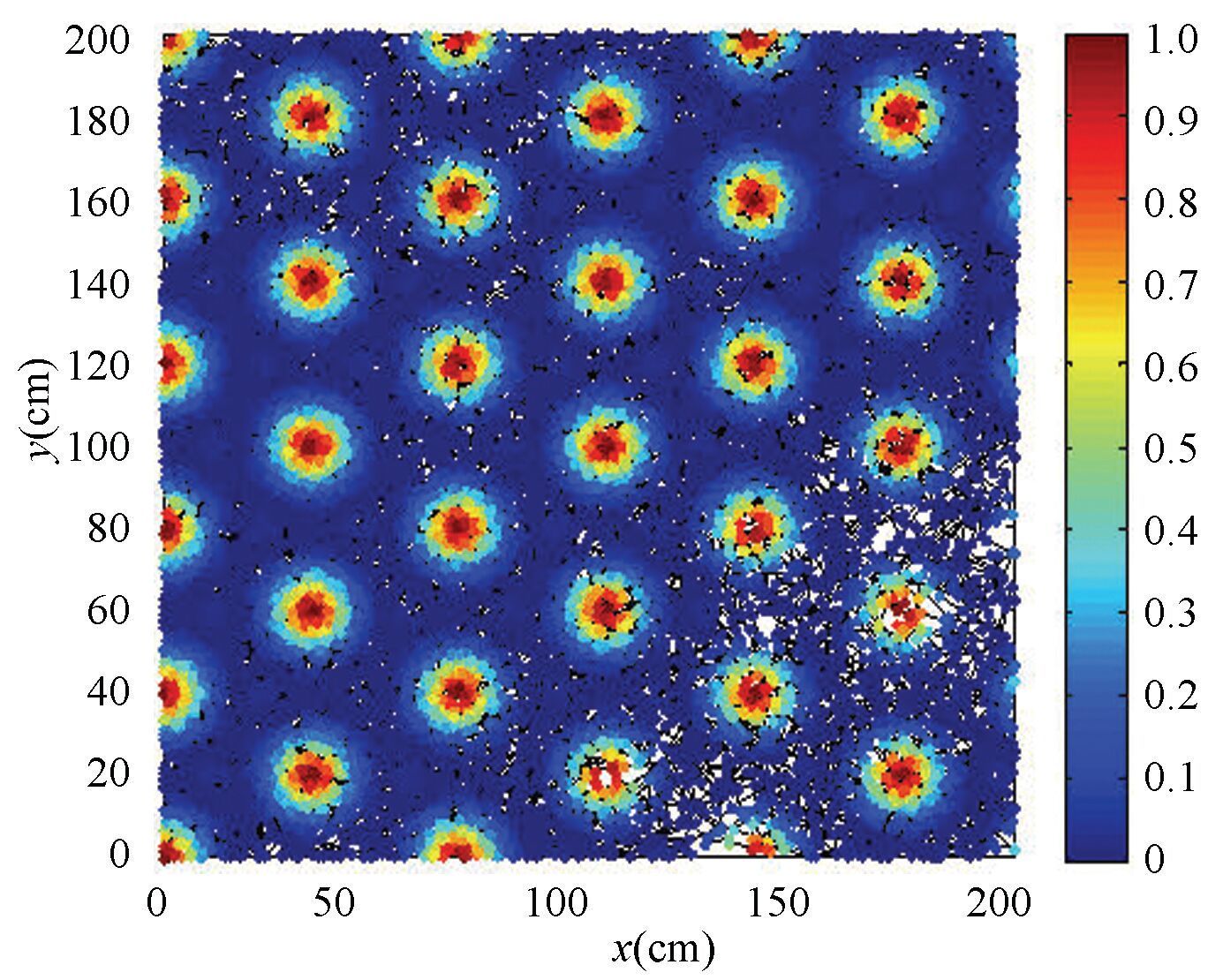
Fig. 9 shows the firing pattern when the grid spacing and firing field radius are changed.The positioning time is 20 000.The new grid spacing A is 40 cm. The new firing field radius r is 15 cm. Compared with the results in Fig. 6(c), the grid spacing and firing field radius of the firing pattern are changed according to the set condition, which proves that the computational model can realize the simulation of grid cells with different grid spacing and firing field.
|
Figure 9 Firing pattern after changing the grid spacing and firing field radius |
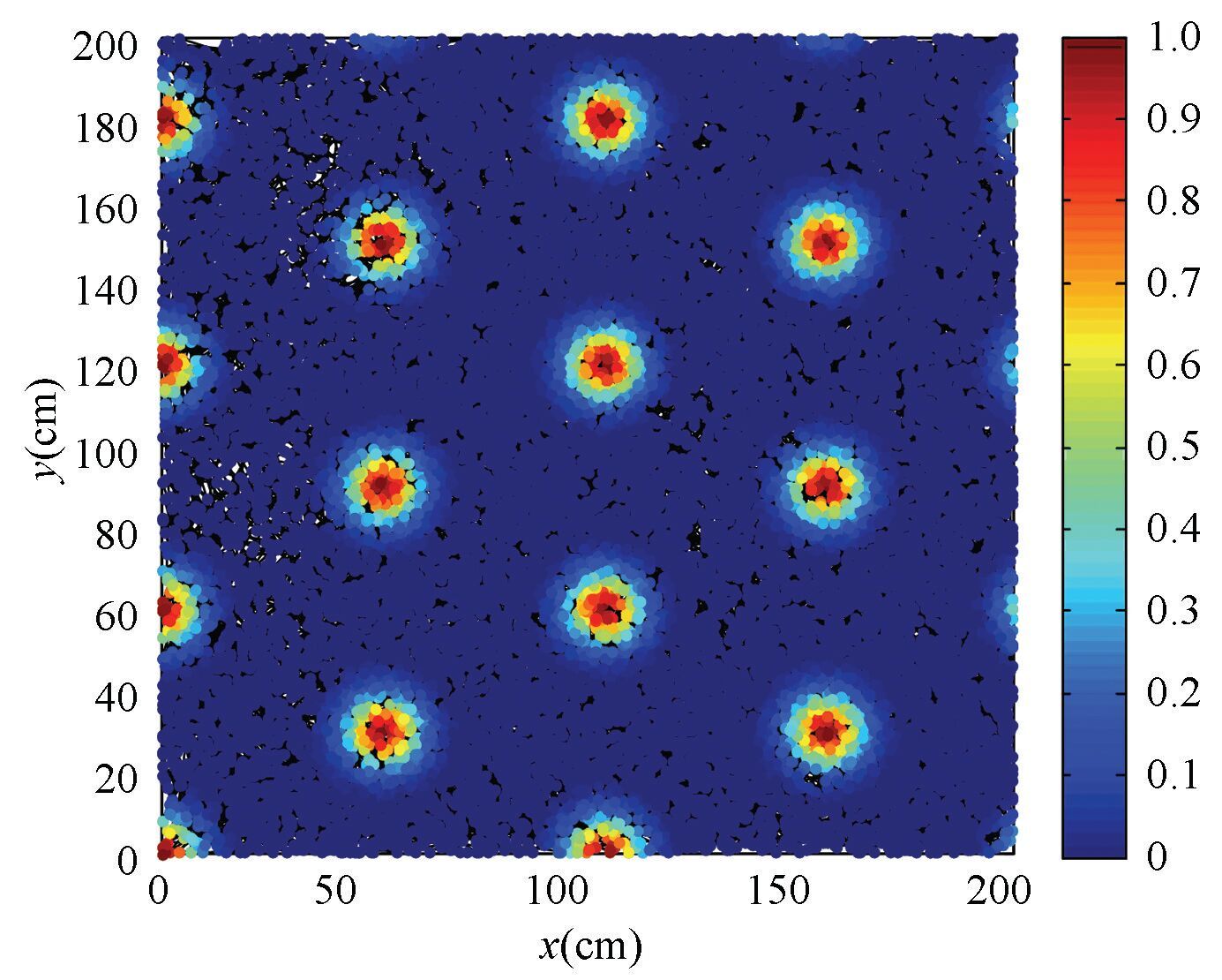
Fig. 10 shows the firing pattern when the running speed is changed. The positioning time is 20 000. The new maximum speed is less than 20 cm/s. Compared with the results in Fig. 6(c), the firing pattern is not changed. So the firing pattern generated by the computational model is independent of the speed, and this characteristic is consistent with that of biological grid cells.
|
Figure 10 Firing pattern after changing the running speed |
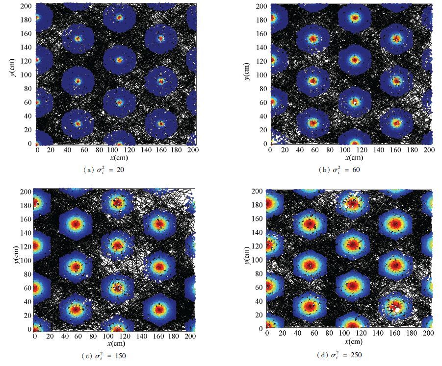
Fig. 11 shows the firing pattern when the adjustment factor of firing rate σi2 is changed. The black lines express the running trajectory. The blank represent the location that the vehicle has not visited. The region from the dark red to dark blue is the firing field (Dark blue expresses minimum firing rate. Dark red expresses maximum firing rate). In the simulation, the positioning time is 20 000. The value of adjustment factor in different experiment is divided four cases, including 20,60,150 and 250, and the adjustment factors of six head direction cells are equal. Simulation results show that: the adjustment factor has no influence on the regularly hexagonal shape and the size of firing field, but it affects the value of firing rate in the firing field.Therefore, the proportion with high firing rate in the firing field can be adjusted by changing the adjustment factor of firing rate
|
Figure 11 Firing pattern after changing the adjustment factor of firing rate |
In summary, the improved computational model of grid cells based on column structure can simulate the firing characteristics of biological grid cells better than original model, and it can generate the firing pattern with different grid spacing, orientation, and firing field by adjusting model parameters. What's more, in the same environment, the firing pattern remains the same shape even though the speed and vehicle trajectory are changed.
4.2 Relation Between Firing Pattern and Positioning ResultsThe firing of grid cells is associated with the space location. In the simulation, the vehicle ′ s location is calculated by path integration, whose result is mainly decided by the speed, direction and the positioning cycle. As is known, in the path integration, positioning error accumulates with the time, and it directly affects the firing of grid cells. Therefore, the influence on the firing pattern from positioning results is discussed in this section.
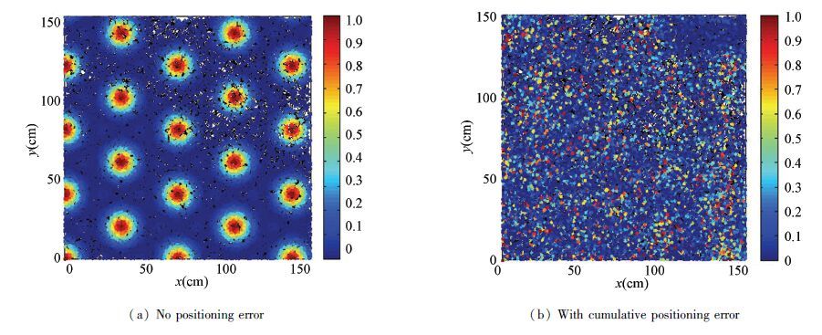
Fig. 12 shows the comparison of firing pattern when there is no positioning error and the cumulative positioning error appears with the time. The positioning time is 20 000, and the positioning error at individual positioning moment is less than 1 cm.The maximum speed of the vehicle is less than 20 cm/s. The positioning cycle T is 1.5 s. The running area E is 150 cm×150 cm. Grid spacing A is 40 cm. Firing field radius is 15 cm. The number of head direction cells N is 6. Adjustment factor of firing rate σi2 is 100. Simulation results show that the firing pattern similar to the biological characteristic can not be formed when there is cumulative positioning error, i.e., the influence on the computational model of grid cells from cumulative positioning error is badly. The reason for this phenomenon is that the firing rate of grid cell is calculated based on the measured location. If the measured location is different from the real location, the firing rate in the real trajectory appears error, which results in disappearance of regularly hexagonal firing pattern.
|
Figure 12 Firing pattern influenced by positioning results |
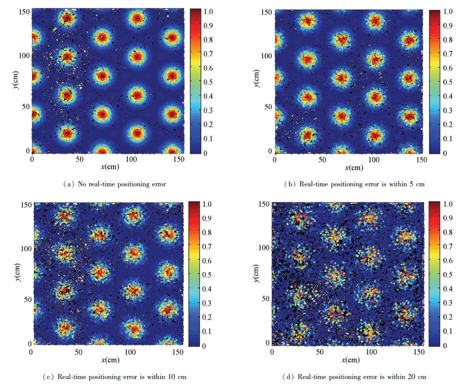
Currently, the existent computational models of grid cells have no good countermeasures to avoid the influence of cumulative positioning error. The main reason is that the positioning error is brought by the sensor, and it has nothing to do with the model itself.The researchers usually think that the cumulative positioning error can be modified by other ways, for example the vision information.So the real-time positioning error can be always less than a certain value.
Fig. 13 shows the firing pattern when the positioning results are modified. The simulation of the modification is implemented by setting the real-time maximum positioning error.The simulation parameters are the same to that in analyzing the influence of cumulative positioning error, but the positioning error at each positioning moment is random distribution.The real-time maximum positioning error is divided into three cases, including 5 cm,10 cm and 20 cm.Simulation results show that the firing rate is influenced by the real-time positioning results. However, if the real-time positioning errors are modified, the computational model can also generate the regularly hexagonal firing pattern.Besides, the higher the positioning precision is, the better the firing pattern can be.As shown in Fig. 13, the firing pattern Fig. 13(b) is better than those of Figs. 13(c) and 13(d).
|
Figure 13 Firing pattern when the positioning error is within a certain value |
To sum up, the model of grid cells is invalidation when there is cumulative positioning error, but it can also generate the similar firing pattern of biological grid cells when the positioning results are modified.
5 ConclusionThe found of grid cells is focused on by navigation researchers who hope their firing characteristics can be used in vehicle navigation, and the simulation of their firing characteristics is an important part that needs to be realized. This paper presents an improved computational model of grid cells based on column structure. The detail process of the improved computational model is discussed, and it is realized by the simulation. Besides, the availability of the model is proved. Simulation results show that the firing pattern generated by the improved model is more consistent with that of biological grid cells than original model, and the firing pattern can be changed by adjusting the model parameters. Simultaneously, the firing pattern is affected by the positioning results, but the computational model can also generate the similar firing pattern of biological grid cells when the real-time positioning error is within a certain value.
| [1] |
O ´ Keefe J, DosLrovskv J. The Hippocampus as a spatial map. Brain Res, 1971, 34: 171-175. ( 0) 0)
|
| [2] |
Hafting T, Fyhn M, Molden S, et al. Microstructure of a spatial map in the entorhinal cortex. Nature, 2005, 436(11): 801-806. ( 0) 0)
|
| [3] |
Giocomo L M, Moser M B, Moser E I. Computational models of grid cells. Neuron, 2011, 71: 589-603. ( 0) 0)
|
| [4] |
Mcnaughton B L, Battaglia F P, Jensen O, et al. Path integration and the neural basis of the ‘cognitive map'. Neuroscience, 2006, 7: 663-678. ( 0) 0)
|
| [5] |
Moser E I, Moser M B. Grid cells and neural coding in high-end cortices. Neuron, 2013, 80: 765-774. ( 0) 0)
|
| [6] |
Erdem U M, Hasselmo M E. A biologically inspired hierarchical goal directed navigation model. Journal of Physiology, 2014, 108: 28-37. ( 0) 0)
|
| [7] |
Guth F A, Silveira L, Amaral M, et al. Underwater visual 3D SLAM using a bio-inspired system. Proceedings of 2013 Symposium on Computing and Automation for Offshore Shipbuilding, 2013, 87-92. ( 0) 0)
|
| [8] |
Tai Nengjian, Wu Dewei, Qi Juyi, et al. Method to realize path integration based on multi-scale grid cells. Journal of Beijing University of Aeronautics and Astronautics, 2013, 39(6): 756-760. ( 0) 0)
|
| [9] |
Burgess N, Barry C, O ′ Keefe J. An oscillatory interference model of grid cell firing. Hippocampus, 2007, 17: 801-812. ( 0) 0)
|
| [10] |
Jeewajee A, Barry C, O ′ Keefe J, et al. Grid cells and theta as oscillatory interference: electrophysiological data from freely moving rats. Hippocampus, 2008, 18: 1175-1185. ( 0) 0)
|
| [11] |
Burgess N, O ′ Keefe J. Models of place and grid cell firing and theta rhythmicity. Nature, Neurobiology, 2011, 21: 734-744. ( 0) 0)
|
| [12] |
Guanella A, Verschure P F M J. A model of grid cells based on a path integration mechanism. Proceedings of ICANN, 2006, 740-749. ( 0) 0)
|
| [13] |
Burak Y, Fiete I R. Accurate path integration in continuous attractor network models of grid cells. Computational Biology, 2009, 5(2): 1-16. ( 0) 0)
|
| [14] |
Islam T, Yamaguchi Y. Representation of an environmental space by grid fields:A study with a computational model of the grid cell based on a column structure. Proceedings of International Joint Conference on Neural Networks.Atlanta, Georgia, 2009, 14-19. ( 0) 0)
|
| [15] |
Islam T, Yamaguchi Y. Some computational predictions on the possibilities of three-dimensional properties of grid cells in entorhinal cortex. Proceedings of ICONIP, 2009, 26-33. ( 0) 0)
|
| [16] |
Islam T, Fukuzaki R. A model of path integration and navigation based on head direction cells in entorhinal cortex. Proceedings of ICONIP, 2010, 82-90. ( 0) 0)
|
| [17] |
Moser E I, Kropff E, Moser M B. Place cells, grid cells, and the brain's spatial representation system. Annu Rev Neurosci, 2008, 31: 69-89. ( 0) 0)
|
| [18] |
Stensola H, Stensola T, Solstad T, et al. The entorhinal grid map is discretized. Nature, 2012, 492: 72-78. ( 0) 0)
|
| [19] |
Rowland D C, Moser M-B. From cortical modules to memories. Curr Opin Neurobiol, 2014, 24: 22-27. ( 0) 0)
|
| [20] |
Doeller C F, Barry C, Burgess N. Evidence for grid cells in a human memory network. Nature, 2010, 463: 656-661. ( 0) 0)
|
| [21] |
O ´ Keefe J, Burges N. Geometrical determinants of the place fields of hippocampus neurons. Nature, 1996, 381: 425-428. ( 0) 0)
|
 2016, Vol. 23


