2. Center for Rubber Composite Materials and Structures, Harbin Institute of Technology, Harbin 150001, China
Tire profile has been received much attention due to the pursuit of highly durable tires to meet the economic, environmental and safe demands[1-2]. Radial tire has inner and outer profile, the inner profile is the contour of the carcass[3], which including restricted part and free part[4] (as shown in Fig. 1). It has greatly influence on the tire performance, because inner profile forms tire cavity and determines the directions of inflation pressure[5]. A good inner profile should have a smaller deformation under the condition of inflation[2], how to obtain a rational inner profile at the stage of design is the focus of researches. One way to design inner profile is using multi-arcs. Nakajima et al.[6] used four arcs to represent the profile of sidewall and bead. Cho et al.[7-8] divided sidewall region into five arcs with different radius, two adjacent arcs were tangent, and the lengths of arcs were given artificially. Another way is to calculate the equilibrium profile by theory or computational mechanic model. Koutny[9] designed the sidewall contour by using equilibrium profile. Akasaka[10] draw the belted radial tire profile by introducing a parameter called allotment ratio of pressure into equilibrium profile. Ghoreishy[11] used net model and membrane model to calculate the equilibrium profile, and it was utilized to describe the sidewall, the result was in good agreement with experiment. Bozdog et al.[12] obtained the equilibrium profile by shell model, and calculated the whole profile of tire, however, the effects of belt were not considered. In addition, non-equilibrium profiles were also investigated by some researches, such as RCOT[13] and TCOT[14], here, only sidewall and bead region were considered, and they were also based on equilibrium profile with small modifications.

|
Figure 1 The belt width and WRCB |
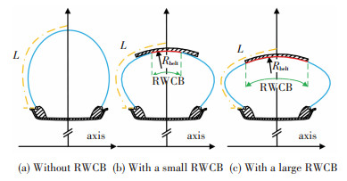
In summary, it can be found that only the free part of carcass contour was studied, however, the restricted part was neglected. How to decide the restriction width of carcass by the belt (RWCB) (as shown in Fig. 1) was not considered carefully. This problem can be described in Fig. 2, with the same length of carcass and belt in the three cross sections of radial tires, the RWCB will be different under inflation, when the distance from belts to axis is different.
|
Figure 2 Tire profiles with different RWCB |
In this paper, the calculating method of RWCB is proposed in the stage of radial tire design. Firstly, an inextensible membrane model is used to calculate the equilibrium profile. Secondly, the equilibrium profile is used to calculate RWCB. Thirdly, a simplified experiment and FEA models are developed to validate the accuracy of the RWCB calculating method, because the finite element method has been used to analyze tire successfully[15-17].Finally, the benefits of this method are investigated by FEA of four designs with different inner profiles.
2 Equilibrium Rofile of Radial TireRadial tire without belts can be simplified to a two-dimensional curve rotating about the central axis, as shown in Fig. 3, A, B and C are the highest, widest and lowest points on tire meridian profile respectively. If the length of the profile is constant, the cavity volume V should be maximum according to the minimum energy principle when the cavity is inflated [18].

|
Figure 3 Two types of radial tire profiles without belts |
The curve on the right side of r axis (radial coordinate of tire profile) can be expressed by z=z(r) (z is the abscissa of tire profile), half-length of the profile is L (the length of the profile between point A and C), and it is assumed to be unchanged approximately before and after inflation. In fact, if the elongation rate ε of the cord is given, the hypothesis is unnecessary, just changes L to (1+ε)L. The L can be integrated by
| $ L{\rm{ = }}\int_{{r_C}}^{{r_A}} {\sqrt {1 + {{\left( {z'} \right)}^2}{\rm{d}}r} } $ | (1) |
The cavity volume can be given by
| $ V\left( z \right) = 4\pi \int_{{r_C}}^{{r_A}} {\sqrt {rz\left( r \right){\rm{d}}r} } $ | (2) |
The curve should meet the boundary condition according to the hypothesis,
| $ V\left( z \right) \to \max \left| {L = {\rm{constant}}} \right. $ | (3) |
This problem can be solved by variational approach (isoperimetric problem)[19], and the Lagrange function is developed by
| $ H = rz + \lambda \sqrt {1 + {{\left( {{z'}} \right)}^2}} $ | (4) |
If H is maximum, z(r) must satisfy the differential equation, which is given by
| $ \frac{{\rm{d}}}{{{\rm{d}}r}}\left( {\frac{{\partial H}}{{\partial {z'}}}} \right) - \frac{{\partial H}}{{\partial z}} = 0 $ | (5) |
Substituting Eq.(4) into Eq. (5), it can be given by
| $ {z'} = \left( {\frac{1}{2}{r^2} + {c_1}} \right)/\sqrt {{\lambda ^2} - {{\left( {\frac{{{r^2}}}{2} + {c_1}} \right)}^2}} $ | (6) |
The boundary conditions are z′(rB)=0 and z′(rA)=∞, so two equations can be established by
| $ \left\{ \begin{array}{l} \frac{1}{2}r_B^2 + {c_1} = 0\;\;\\ {\lambda ^2} - {\left( {\frac{{r_A^2}}{2} + {c_1}} \right)^2} = 0 \end{array} \right. \Rightarrow \left\{ \begin{array}{l} {c_1} = - \frac{{r_B^2}}{2}\\ {\lambda ^2} = {\left( {\frac{{r_A^2}}{2} - \frac{{r_B^2}}{2}} \right)^2} \end{array} \right. $ | (7) |
So, the curve can be expressed by
| $ z = \int_r^{{r_A}} {\frac{{{r^2} - r_B^2}}{{{{\left( {r_A^2 - r_B^2} \right)}^2} - {{\left( {{r^2} - r_B^2} \right)}^2}}}} {\rm{d}}r $ | (8) |
And the radius of curvature of the points on the profile is given by
| $ \rho \left( r \right) = \frac{{{{\left( {1 + {{\left( {{z'}} \right)}^2}} \right)}^{3/2}}}}{{{z^{''}}}} = \frac{r}{\lambda } = \frac{{r_A^2 - r_B^2}}{{2r}} $ | (9) |
Eq.(8) is the same as Day’s[20]. Eq.(9) was also reported in RCOT[13] and TCOT[14]. The curve above does not contain belt, so it can be called tire profile without belt.
In fact, there are two types of profiles without belt: one is rB>rC and the other is rB < rC, as shown in Fig. 3, which are controlled by the lengths of profiles. In general, the type (a) profile is used in TBR, and type (b) can be used in the tires with low aspect ratio. For example, in the high-speed passenger car tires, rB is moved upward when the belt is added. The critical length of cord between the two types can be obtained by Eq.(1), just making rB=rC, the critical length can be obtained by
| $ {L_C} = \int_{{r_c}}^{{r_A}} {\frac{{{{\left( {r_A^2 - r_C^2} \right)}^2}}}{{{{\left( {r_A^2 - r_C^2} \right)}^2} - {{\left( {{r^2} - r_C^2} \right)}^2}}}} {\rm{d}}r $ | (10) |
Next, the profiles with belts have been studied. There are two types of belts: curved and flat, as shown in Fig. 4, in order to simply calculation and drawing, curved belts are assumed to be arcs usually[3], in fact, they can be any kinds of curves. Radial tire with curved and flat belts are abbreviated as RTCB and RTFB respectively. The belts are assumed to be rigid, carcasses are regarded as flexible, and the restricted part by belt must coincide with the belt. In other words, the belt and carcass must be tangent at the demarcation point K.

|
Figure 4 Radial tires with different belts |
The cavity volume of tire can be divided into two parts: V1 (the cavity volume under free carcass) and V2 (volume cavity under restricted carcass), seen in Fig. 4. When the length and radius of belt are given, V2 can be regarded as a constant, and then the whole volume is calculated by
| $ V = 2\left( {{V_1} + {V_2}} \right) $ | (11) |
See above, the maximizing V is equal to maximize V1, so, the profile between point K (demarcation point between belt and carcass) and point C must be in accordance with Eq.(6).
For RTFB, the boundary conditions are z′(rB)=0 and z′(rK)=∞, rK=rA, so the profile of RTFB is similar to Eq.(8), the curve is expressed by
| $ z = {z_K} + \int_r^{{r_A}} {\frac{{{r^2} - r_B^2}}{{\sqrt {{{\left( {r_A^2 - r_B^2} \right)}^2} - {{\left( {{r^2} - r_B^2} \right)}^2}} }}} {\rm{d}}r $ | (12) |
For RTCB, the boundary conditions are z′(rB)=0 and z′(rK)=k (the slope of tire profile at point K). Substituting these conditions into Eq.(6), the equilibrium profile of RTCB can be expressed by Eq.(13).
| $ z = {z_K} + \int_r^{{r_K}} {\frac{{{r^2} - r_B^2}}{{\sqrt {\frac{{{k^2} + 1}}{{{k^2}}}{{\left( {r_K^2 - r_B^2} \right)}^2} - {{\left( {{r^2} - r_B^2} \right)}^2}} }}} {\rm{d}}r $ | (13) |
The curvature radius of the RTCB profile can be calculated by
| $ \rho \left( r \right) = \frac{{\sqrt {{k^2} + 1} }}{{{k^2}}} \cdot \frac{{r_K^2 - r_B^2}}{{2r}} $ | (14) |
It is worth noting that the curve expression of RTFB is different from RTCB. The curvature radius of RTCB is different from RCOT[13] and TCOT[14], there is an additional coefficient in Eq.(14) comparing with Eq.(9), which indicates that the k also affects ρ(r).
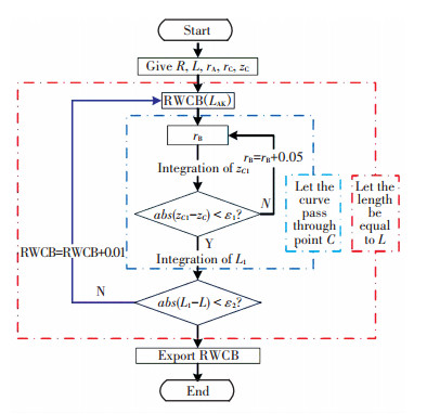
3 Method of Calculating RWCBThere are two restrictions when the membrane is contacting with rigid shell: (1) the membrane is fixed at point C, so the curve must pass through point C; (2) the membrane is inextensible, so half length of the generatrix must be equal to L. In the progress of calculation, the value of rB and RWCB are adjusted to meet the two conditions, the curve and RWCB can be obtained. The calculation process is shown in Fig. 5.
|
Figure 5 A flowchart of the calculation process |
Where zC1 and L1 are the calculated values of zC and L in the calculation process, R is the radius of curvature of belt. If they satisfy the conditions in Fig. 5, which means that the profile will pass through point C and half length of generatrix is L, the calculation progress is ending. zC1 is obtained by integrating Eq.(12) or Eq.(13), L1 obtained is by Eq.(15), and the LCK (carcass length between point C and point K) is obtained by integrating Eq.(16), LAK is carcass length between point A and point K.
| $ L = {L_{AK}} + {L_{CK}} $ | (15) |
| $ {L_{CK}} = \int_{{r_C}}^{{r_K}} {\sqrt {1 + {{\left( {{z'}} \right)}^2}} } {\rm{d}}r $ | (16) |
The Eq.(12), Eq.(13) and Eq.(16) are all elliptic integrals, so the numerically evaluated integral is used. The method can be expressed by Eq.(17) and Eq.(18), which is composite Simpson’s rule of numerical integration[21].
| $ \begin{array}{l} \int_a^b {f\left( x \right){\rm{d}}x} = \sum\limits_{k = 0}^{n - 1} {\int_{{x_k}}^{{x_{k + 1}}} {f\left( x \right){\rm{d}}x} } \approx \frac{h}{6}\left( {f\left( a \right) + } \right.\\ \;\;\;\;\;\;\;\;\;\;\;\;\;\;\;\;\;\;\;\left. {4\sum\limits_{k = 0}^{n - 1} {f\left( {{x_{k + \frac{1}{2}}}} \right) + 2\sum\limits_{k = 1}^{n - 1} {f\left( {{x_k}} \right) + f\left( b \right)} } } \right) \end{array} $ | (17) |
| $ \begin{array}{l} {R_s} = - \frac{{b - a}}{{180}}{\left( {\frac{h}{2}} \right)^4}{f^{\left( 4 \right)}}\left( \eta \right) = - \frac{{b - a}}{{\sqrt 2 }}{h^4}{f^{\left( 4 \right)}}\left( \eta \right),\\ \;\;\;\;\;\;\;\;\;\;\;\;\eta \in \left[ {a,b} \right] \end{array} $ | (18) |
Where a and b are upper and lower limits of integration, h is the size of integrating step, h=(b-a)/n, RS is the error.
The error can be set in advance, and h can be obtained according to the error. When the calculation is over, the profile and RWCB can be obtained.
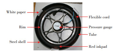
4 Method ValidationRestriction of carcass by the belt can be represented by the restriction of inextensible membrane by axisymmetric rigid shell[22], the rigid shell may be cylindrical or double-curved, and they represent flat and curved belts respectively. In order to measure RWCB, an experimental device is built, which is seen in Fig. 6. A rubber tube is mounted on the steel rim, the width and diameter of the rim are 58 mm and 430 mm respectively. A steel shell is placed outside the tube, which is coaxial. The width, thickness and diameter of the shell are 150 mm, 1 mm and 540 mm respectively. The tube will contact with the shell when it is inflated. The deformation of shell and rim are extremely small, they can be regard as rigid.
|
Figure 6 The experimental device for measuring the RWCB |
Before inflated, the tube is painted by red inkpad in its outside surface. Three white papers are placed close to the shell separately, which are used to measure the RWCB. In order to obtain perimeter of the tube, three flexible cords are placed around the tube; when the tube is inflated, they are marked at the intersection points with rim on both sides; the length between the two intersection points is the perimeter. A pressure gauge is used to measure the pressure inside the tube with the measuring range of 0-60 kPa and the accuracy of 1 kPa.
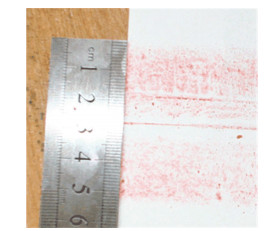
When the tube is inflated, there is an imprint on the paper, which shows the contact area between tube and shell (as shown in Fig. 7). Here, the RWCB is the width of the area.
|
Figure 7 The imprint of the tube with shell and RWCB |
The finite element method is also used to analyze the restriction width of membrane by rigid shell, because the double curved shell is difficult to make experimentally. In the axisymmetric finite element model, the rigid shell is located coaxially with the membrane. In order to impose boundary conditions easily, one degree of the membrane is used as a sub-model. The cylindrical coordinates is used, as shown in Fig. 8(a).

|
Figure 8 Cylindrical coordinate system and finite element models |
The initial shape of the membrane is determined by Eq.(8), the boundaries are fixed in the circumferential direction (θ direction), and a displacement of the rigid shell towards the axis along the radial direction (r direction) is given, as shown in Fig. 8(b) and Fig. 8(c). The whole model can be represented perfectly by the sub-model. The modulus of membrane is 1.24 MPa, Poisson’s ratio is 0.35, the inflation pressure is 0.033 8 kPa, and the strain is very small in the simulation.
The parameters of two different tires are shown in Table 1, which have also been used by Koutny[9]. The values of R are changing in order to obtain more data. The R of 8.5R17.5 tire is infinity, which implies the belt is flat.
| Table 1 Parameters of 12R22.5 and 8.5R17.5 tires |
5 Benefits Investigation
According to the method in Fig. 5, the RWCB can be calculated when R, L, rA, rC and zC are given. However, the given parameter zB is always instead of L in the stage of initial design, so it just change the constraint of L to zB in the method. Here, the RWCB is confirmed when R, zB, rA, rC and zC are given.
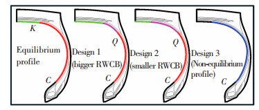
Four different 295R22.5 tires (seen in Fig. 9) are designed to verify the benefits of this method, which have the same R, zB, rA, rC and zC. The parameter values of 295R22.5 tire are shown in Table 2.
|
Figure 9 Four different designs of 295R22.5 tire |
| Table 2 Parameter values of 295R22.5 tire |
The first design is using the profile obtained by this paper’s method; Design 1 and Design 2 are partial equilibrium profile with a larger and smaller RWCB respectively; Design 3 is non-equilibrium profile. Design 1 and Design 2 are both modified from the equilibrium profile[18].
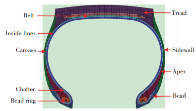
The finite element model is developed by using ABAQUS software, and REBAR elements are used to represent the cords of carcass, belts, and chafer. The four FEA models have the same meshes except small differences at shoulders, and they have the same materials. The inflation pressure is 0.9 MPa, parts and meshes of the 295R22.5 tire are shown in Fig. 10.
|
Figure 10 Parts and meshes of the 295R22.5 tire |
Uniaxial tension tests are carried out for rubber materials by ISO 37∶2005. Based on this, parameters of constitutive model are obtained by fitting stress-strain datas. Here, Yeoh model (seen in Eq.(19)) is used for Carcass and Apex rubber materials and Mooney-Rivlin model (seen in Eq.(20)) is used for the other rubber materials according to the goodness of fit. The parameter values of rubber materials are shown in Table 3.
| $ W = {C_{10}}\left( {{I_1} - 3} \right) + {C_{20}}{\left( {{I_1} - 3} \right)^2} + {C_{30}}{\left( {{I_1} - 3} \right)^3} $ | (19) |
| $ W = {C_{10}}\left( {{I_1} - 3} \right) + {C_{01}}\left( {{I_2} - 3} \right) $ | (20) |
| Table 3 Parameter values of rubber materials |
where W is the strain energy density function, I1 and I2 are the first and second invariant, Cij (i, j=1, 2, 3) are the coefficients.
Linearly elastic model is used for the reinforcement materials. The parameter values of reinforcement materials are shown in Table 4.
| Table 4 Parameter values ofreinforcement materials |
6 Results and Discussion
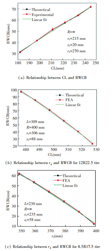
The numerical calculations are carried on a computer with 8G RAM and 8-core processors, run time for each calculation is about 5 min. All the finite element simulations are carried out by using ABAQUS/Standard on the same computer, and run time for each simulation is about 25 min. ε1 and ε2 are both equal to 0.2 in this calculation, Rs is equal to 1e-8. The results are shown in Fig. 11.
It can be seen that the theoretical results are in good agreement with experimental and FEA results, which validate the accuracy of this method. An approximate linear relationship between CL (the whole length of carcass) and RWCB can be observed in Fig. 11(a), and the similar linear relationship exists between rA and RWCB, shown in Fig. 11(b) and Fig. 11(c). The error between theoretical results and FEA results may be caused by three reasons: (1) it is from the calculation process (seen in Fig. 5), the two restrictions of zC and L are not met strictly; there are deviations of 0.5 mm between zC and zC1, and 1 mm between L and L1, the errors can be decreased by setting a smaller ε1 and ε2; however, it may increase the calculation time; (2) it is from the FEA model, inflation pressure may lead to elongation of the shell, which is equivalent to increase the length of carcass; (3) it is from the experiment.
|
Figure 11 Theoretical, experimental and FEA results of RWCB |
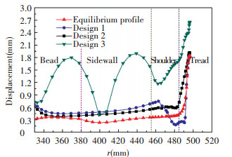
From Fig. 12 we know that displacement of equilibrium profile is smaller and more uniform than the others, which verifies the benefits of this paper’s method. Due to the expansion of belt under inflation pressure, all these designs have large deformations at tread. The bending of belt lead to decrease of belt radius and increase of RWCB, Design 1 has a larger RWCB, which is the reason of smaller displacement at shoulder of Design 1. However, the change of RWCB leads to a change of k, which affects the profile in bead. Design 3 is the non-equilibrium profile, here, the displacement of carcass is very large and un-uniform.
|
Figure 12 The displacements of carcasses of four 295R22.5 tire |
7 Conclusions
The method of calculating RWCB introduced in this paper is proved to be correct and its advantage is validated. According to experimental results and the analyses above, we have the following points:
1)The equilibrium profile of RTFB is different from RTCB, the latter has two different parameters which are rK and k;
2)An approximate linear relationship exists between CL and RWCB, and the relationship between rA and RWCB is also linear if the CL and R are constant;
3)The equilibrium profile is more stable than others, which validates the advantages of this paper’s method.
This method can play a key role in tire design.However, further problems should to be studied is the determination of the point C and its effects on tire performances.
| [1] |
Nakajima Y. Application of computational mechanics to tire design—yesterday, today, and tomorrow.
Tire Science and Technology, 2011 , 39 (4) : 223-244.
DOI:10.2346/1.3670034 ( 0) 0)
|
| [2] |
Bauer R F. Equilibrium profile of modern belted radial ply tires: its determination and performance benefits.
Tire Science and Technology, 2013 , 41 (2) : 127-151.
( 0) 0)
|
| [3] |
Akasaka T. Structural mechanics of radial tires.
Rubber Chemistry and Technology, 1981 , 54 : 461-492.
DOI:10.5254/1.3535818 ( 0) 0)
|
| [4] |
Curtiss W W. Principles oftire design.
Tire Science and Technology, 1973 , 1 (1) : 77-98.
DOI:10.2346/1.2167156 ( 0) 0)
|
| [5] |
Clark S K.
Mechanics of Pneumatic Tires. Washington DC: U.S. Government Printing Office, 1982 : 203 -248.
( 0) 0)
|
| [6] |
Nakajima Y, Kamegawa T, Ogawa H. Theory of optimum tire contour and its application.
Tire Science and Technology, 1996 , 24 (3) : 184-203.
DOI:10.2346/1.2137518 ( 0) 0)
|
| [7] |
Cho J R, Jeong H S, Yoo W S. Multi-objective optimization of tire carcass contours using a systematic aspiration-level adjustment procedure.
Computational Mechanics, 2002 , 29 (6) : 498-509.
DOI:10.1007/s00466-002-0359-2 ( 0) 0)
|
| [8] |
Cho J R, Jeong H S, Kim N J, et al. Application of STOM to the optimal tire contour design by introducing the aspiration-level indicator.
Tire Science and Technology, 2002 , 30 (4) : 265-288.
DOI:10.2346/1.2135258 ( 0) 0)
|
| [9] |
Koutny F. Load-deflection curves for radial tyres.
Applied Mathematical Modelling, 1981 , 5 (6) : 422-427.
DOI:10.1016/S0307-904X(81)80025-X ( 0) 0)
|
| [10] |
Akasaka T. Structural mechanics of radial tires.
Rubber Chemistry and Technology, 1981 , 54 (3) : 461-492.
DOI:10.5254/1.3535818 ( 0) 0)
|
| [11] |
Ghoreishy M H R. Pneumatic tire modeling by membrane method.
Iranian Polymer Journal, 1993 , 2 (1) : 37-43.
( 0) 0)
|
| [12] |
Bozdog D, Olson W W. An advanced shell theory based tire model.
Tire Science and Technology, 2005 , 33 (1) : 227-238.
( 0) 0)
|
| [13] |
Yamagishi K, Togashi M, Furuya S, et al. A study on the contour of the radial tire: rolling contour optimization theory—RCOT.
Tire Science and Technology, 1987 , 15 (1) : 3-29.
DOI:10.2346/1.2148779 ( 0) 0)
|
| [14] |
Ogawa H, Furuya S, Koseki H, et al. A study on the contour of the truck and bus radial tire.
Tire Science and Technology, 1990 , 18 (4) : 236-261.
DOI:10.2346/1.2141702 ( 0) 0)
|
| [15] |
Kaliske M, Serafinska A, Zopf C. Optimized and robust design of tires based on numerical simulation.
Tire Science and Technology, 2013 , 41 (2) : 21-39.
( 0) 0)
|
| [16] |
Bauer R F. Equilibrium profile of modern belted radial ply tires:its determination and performance benefits.
Tire Science and Technology, 2013 , 41 : 127-151.
( 0) 0)
|
| [17] |
Chauhan M R, Kotwal G, Majge A. Numerical Simulation of Tire and Wheel Assembly Impact Test Using Finite Element Method.
SAE Technical Paper, 2015 .
( 0) 0)
|
| [18] |
Wang Youshan, Cui Zhibo, Wu Jian, et al. An improved method of using equilibrium profile to design radial tires.
Journal of Advanced Mechanical Design, Systems, and Manufacturing, 2015 , 9 (2) : JAMDSM0018-JAMDSM0018.
DOI:10.1299/jamdsm.2015jamdsm0018 ( 0) 0)
|
| [19] |
Daniel Liberzon, Calculus of Variations and Optimal Control Theory: A Concise Introduction. Princeton: Princeton University Press, 2012. 71-101.
( 0) 0)
|
| [20] |
Day R B, Gehman S D. Theory for the meridian section of inflated cord tires.
Rubber Chemistry and Technology, 1963 , 36 (1) : 11-27.
DOI:10.5254/1.3539531 ( 0) 0)
|
| [21] |
WalterGautschi, Numerical Analysis. 2nd ed. Boston: Birkhauser. Boston Inc, 2012.
( 0) 0)
|
| [22] |
De Eskinazi J, Soedel W, Yang T Y. Contact of an inflated toroidal membrane with a flat surface as an approach to the tire deflection problem.
Tire Science and Technology, 1975 , 3 (1) : 43-61.
DOI:10.2346/1.2167195 ( 0) 0)
|
 2016, Vol. 23


