2. State Key Laboratory of Ocean Engineering, Shanghai Jiaotong University, Shanghai 200240, China
Compared with mono hull, catamaran has a bigger deck area. Two slender demihulls cause better direction stability and transverse stability. It also has a well resistance performance. Hence, the catamaran plays an important role in coastal shipping and inland water navigation.
Because catamaran has two parallel demihulls, it is very different from mono hull. The space between two demihulls is not very large, so the velocity of fluid augments. There is also wave field interaction between the demihulls. Therefore, the flow field is different in the inward and outward of catamaran. The study on the interference effects has become an important research field. Many researchers did experiments and simulation calculation to research the interference effects of catamaran, and try to reduce the resistance by reduce the interference effects. Antonio et al.[1] discussed the interference effects of the catamaran with S60 demihulls in different hull separations and fixed-free trim-sinkage conditions based on experiments. Riccardo et al.[2] also carried out some experiments to investigate the interference effects in different Froud number. When the Froud number is less than 0.3 or more than 0.7, the wave interference effects are less evident. Li et al. [3] used panel method in time domain to calculate the wave-making resistance of catamaran with two different size demihulls. Then Li et al.[4] used this method to optimize the demihull’s position in order to reduce the wave-making resistance. Devrim[5] designed a centerbulb between the demihulls to reduce the wave interference effects. And they used Artificial Neural Network to optimize the centerbulb.
Because of the different flow field in two sides, the demihull has two different shape design which aim to the different flow field in two sides having better resistance performance.
Many papers have been published about the resistance of the catamarans with asymmetrical hulls. Kaklis et al.[6]developed and presented an analytical-numerical method for the calculation of the wave resistance of catamaran with asymmetrical hulls. Then an extension of the Michell approach was established by Popanikolau et al.[7] for the calculation of the wave resistance of catamarans with asymmetrical hulls. Wang[8] compared the wave-making resistance of three catamarans which have the same main dimensions. The wave-making resistance of inner flat catamaran is lower than the other catamaran. Bruzzone et al.[9] investigated the influence of some key parameters on resistance of catamarans, comparing a symmetrical hull with a non-symmetrical hull at the same displacement. Utama et al.[10]considered that as hull separation and stagger are increased, resistance decreases. Cirello et al.[11] investigated the shape of catamaran with asymmetrical hulls by both experimental and numerical viewpoint. And the catamaran is optimized by the CFD application by force of commercial software. Zaraphonitis et al.[12] compared the resistance of inner flat, outer flat and symmetrical demihulls catamaran which have the same main dimensions. The total resistance of the inner flat catamaran is lower than the other catamaran when the speed in the low-speed area and high-speed area. But in the medium-speed area, the outer flat catamaran has the lowest total resistance.
In the study on resistance performance of high-speed catamaran, researchers usually use model test and CFD simulation to predict the resistance of ship model. And then the two-dimensional method or three-dimensional method are adopted to estimate the resistance of actual ship. In two-dimensional method, viscous pressure resistance and wave-making resistance have been combined for residuary resistance. This approach is not appropriate in theory. And it also uses equivalent plank frictional resistance to replace frictional resistance. This will cause a significant error in total resistance. Three-dimensional method improves these two imperfections[13-14]. In three-dimensional method, form factor affects the accuracy of actual ship resistance prediction. Researchers normally use direct measurement method, slow speed test and CFD method to estimate the form factor.
In direct measurement method, researchers estimate viscous resistance by measuring the velocity field of model after the stern. There is another method that the wave resistance can be calculated from the description of the far-field wave systems using Eggers coefficient[15]. Then the viscous resistance can be calculated to estimate the form factor.
Slow speed test is improved from Prohaska method in 15th ITTC. It assumes that the total resistance coefficient can be expressed by a function related to form factor, Froud number and equivalent plank frictional resistance coefficient. Then according to model test data, researchers can obtain the form factor by least square method[16-17].
With the development of CFD technology, CFD becomes a powerful tool of ship resistance performance researching. By solving the viscous flow around the hull without free surface, researchers can suppress the interference of free surface, and obtain the viscous resistance. Then the form factor is further calculated by the viscous resistance. Compared with the model test, CFD method has a lower cost, and it can simulate a number of complex phenomena.
Insel et al.[18] summarized a calm-water-resistance investigation into high-speed catamarans with symmetrical hull forms based on experimental work. An equation was proposed to express the total resistance of catamaran:
| $ {C_t} = \left( {1 + \phi k} \right)\sigma {C_F} + \tau {C_W} $ |
The factor ϕ has been introduced to take account of the pressure-field change around the demihulls and σ takes account of the velocity augmentation between the hulls and would be calculated from an integration of the local frictional resistance over the wetted surface, while (1+k) is the form factor for the demihull in isolation. For practical purpose, ϕ and σ can be combined into a viscous inference factor β where (1+k)σ=(1+βk). Hence
| $ {C_T} = \left( {1 + \beta k} \right){C_F} + \tau {C_W} $ |
For a catamaran, τ can be calculated from the equation:
| $ \tau = \frac{{{C_{WCAT}}}}{{{C_{WDEMI}}}} = \frac{{{{\left[ {{C_T} - \left( {1 + \beta k} \right){C_F}} \right]}_{CAT}}}}{{{{\left[ {{C_T} - \left( {1 + k} \right){C_F}} \right]}_{DEMI}}}} $ |
But the form factor and wave-making resistance coefficient of asymmetrical demihullin isolation is not easy to calculate. Therefore, we can’t use the equation to calculate the total resistance of high-speed catamaran with asymmetrical hulls. It is necessary to use another method to calculate the form factor of the catamaran with asymmetrical hulls.
This paper focuses on the study on the form factor of high-speed catamaran with asymmetrical hulls by using CFD method. The viscous resistance and wave-making resistance are calculated in a large speed area. Then these two resistances are combined to calculate total resistance. And the total resistance is compared with the model test result to verify the reliability of the CFD method. Analyzing the results, we find that the form factor of high-speed catamaran is the same as the form factor calculated by Prohaska method. But as the speed increase, the form factor also increases, then reach a peak value. Then the form factor decreases with an increase of speed. Therefore, when studying on the resistance performance of high-speed catamaran, the form factor cannot be simply estimated by low-speed model test or measurement in a specific speed. By using CFD method, the form factor in high speed is more accurate.
2 CFD Method 2.1 Resistance Calculation Method of High-Speed CatamaranIn this paper, it will focus on a 2000-toners high-speed catamaran. The length between perpendiculars of ship model is 3.03 m.
The viscous resistance is calculated by using the theory of viscous flow. The number of grid is about 1.25 million.
The governing equations include continuity equation and RANS equation.
| $ \begin{gathered} \frac{{\partial {U_i}}}{{\partial {x_i}}} = 0 \\ \rho = \frac{{\partial \left( {{U_i}{U_j}} \right)}}{{\partial {x_j}}} = - \frac{{\partial P}}{{\partial {x_i}}} + \rho {g_i} + \rho \bullet \frac{\partial }{{\partial {x_j}}}\left[ {v\left( {\frac{{\partial {U_i}}}{{\partial {x_j}}}} \right.} \right. + \\ \left. {\left. {\frac{{\partial {U_j}}}{{\partial {x_i}}}} \right)} \right] - \frac{{\partial \left( {\rho \overline {{{u'}_i}{{u'}_j}} } \right)}}{{\partial {x_j}}} \\ \end{gathered} $ |
where Ui and Uj are the time-average value of velocity component; P is the time-average value of pressure; ρ is fluid density; gi is component of acceleration of gravity;
Compared with DNS method and LES method, RANS method reduces the calculated quantity. At the same time, it also has certain accuracy. Therefore, this paper uses RANS method to calculate the viscous resistance. But the RANS method also has some limits. There is no one turbulent model can express all turbulent motion. Different situations must choose different turbulent models. The quality of grid and the numerical discrete format affect the accuracy of results[19].
According to the situation, SST(Shear Stress Transport) is selected as the turbulent model. This model was first used in aero aviation. Because of its excellent forecast performance, it was adopted by some commercial software.
SST k-ω model:
Transport equation of k
| $ \frac{\partial }{{\partial {x_i}}}\left[ {\left( {\mu + {\sigma _k}{\mu _t}} \right)\frac{{\partial k}}{{\partial {x_i}}}} \right] $ |
Transport equation of ω
| $ \begin{gathered} \frac{{\partial \left( {\rho \omega } \right)}}{{\partial t}} + \frac{{\partial \left( {\rho {U_i}\omega } \right)}}{{\partial {x_i}}} = \alpha \rho {S^2} - \beta \rho {\omega ^2} + \hfill \\ \frac{\partial }{{\partial {x_i}}}\left[ {\left( {\mu + {\sigma _\omega }{\mu _t}} \right)\frac{{\partial \omega }}{{\partial {x_i}}}} \right] + 2\left( {1 - {F_1}} \right)\rho {\sigma _{\omega 2}}\frac{1}{\omega }\frac{{\partial k}}{{\partial {x_i}}} \bullet \frac{{\partial \omega }}{{\partial {x_i}}} \hfill \\ \end{gathered} $ |
Compared with Wilcox k-ω turbulent model, SST turbulent model takes full account of the transport properties of turbulent shear stress. And it can accurately predict the flow separation point and area caused by adverse pressure gradient. This model was based on k-ω and k-ε turbulent models. And it considers transport effect in turbulent viscous coefficient. So it is more advanced than k-ω two-equation model.
Nowadays, the mainstream wave-making resistance calculation method includes four classes: Michell method, Havelock method, Dawson method and nonlinear theory method. The wave-making resistance of catamaran calculated by linear wave-making theory has disparity from experiment result. Compared with linear wave-making theory, Dawson method obtains the wave-making resistance by the integral for pressure of demi-hulls. And it also includes the non-linear effects. The calculation result is more accuracy. Hence, this paper adopts Dawson method to calculate wave-making resistance[20].
Most of the potential flow models are based on boundary element method.
The velocity potential equation:
| $ \varphi \left( p \right) = \frac{1}{{4\pi }}\int\limits_S {\sigma \left( p \right)G\left( {p,q} \right)dS} $ |
or
| $ \varphi \left( p \right) = \frac{1}{{4\pi }}\int\limits_S {\left[ {\varphi \frac{\partial }{{\partial n}}G\left( {p,q} \right) - G\frac{{\partial \varphi }}{{\partial n}}} \right]dS} $ |
where S is the boundary of the flow field; σ(q) is the intensity of the source distributed on the boundary. These means, the velocity potential function value of a point p in the flow field can be expressed by the intensity of the source σ(q) distributed on the boundary S. It can be also expressed by the potential function and its normal derivative distributed on the boundary S.
If the Green function is confirmed, under a certain boundary condition, the intensity of the source or the unknown function and the value of its normal derivative on the boundary can be solved.
The Dawson method uses the Rankine source as the Green function:
| $ G\left( {p,q} \right) = \frac{1}{{r\left( {p,q} \right)}} $ |
This source is very simple. It does not satisfy any specified conditions except fundamental solutions of Laplace equation. The boundary S includes the body surface and free surface. Therefore, the Dawson method is widely used in the linear problems, nonlinear problems, steady or unsteady problems as long as the control function is Laplace equation.
In this paper, FLUENT is used to calculate the viscous resistance, and SHIPFLOW is used to calculate the wave-making resistance.
The scale ratio is 32, and the length between perpendiculars of ship model is 3.03 m, draught is 0.124 m. The initial trim angle is 0°. Water temperature is 24.5 ℃, the depth of the tank is 5 m.
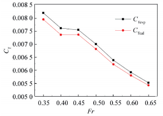
As shown in Table 1 and Fig. 1, we can see that the error between calculated results and experiment results is less than 5%. When the speed is around 36 knot, which is the design speed, the error is about 3%.
| Table 1 Calculation results and experimental results of 2000-toners catamaran |

|
Figure 1 Total resistance coefficient |
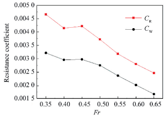
And the residual resistance coefficient is calculated from the experimental results. As shown in Fig. 2, compared with the residual resistance coefficient, the tendency of the wave-making resistance coefficient curve is the same. So we can consider that the calculate results of wave-making resistance is accurate. And this method has a high accuracy when calculating the high-speed catamaran resistance.

|
Figure 2 Residual resistance and wave-making resistance coefficient |
2.2 High-speed Catamaran form Factor Estimation
Three-dimension method is usually used in conversion for actual ship resistance. Three-dimension method considers that the viscous pressure resistance and frictional resistance can be combined for viscous resistance. The viscous resistance is related to Reynolds number. And the wave-making resistance is related to Froud number. Three-dimension method introduces a form factor k. This method considers that the form factor is equivalent to the ratio between viscous pressure resistance coefficient and frictional resistance coefficient.
| $ k = {C_{{\text{pv}}}}/{C_{\text{f}}}\;{\text{or}}\;1 + k = {C_v}/{C_{\text{f}}} $ |
The form factor only related to the hull shape.
The model total resistance coefficient is:
| $ {C_{{\text{tm}}}} = \left( {1 + k} \right){C_{{\text{fm}}}} + {C_{{\text{wm}}}} $ |
The actual ship total resistance coefficient is:
| $ {C_{{\text{ts}}}} = \left( {1 + k} \right){C_{{\text{fs}}}} + {C_{{\text{ws}}}} $ |
According to these two equations:
| $ {C_{{\text{ts}}}} = {C_{{\text{tm}}}} - \left( {1 + k} \right)\left( {{C_{{\text{fm}}}} + {C_{{\text{ws}}}}} \right) $ |
In the model test of 2000-toners catamaran, the equation proposed in 15th ITTC is used to bind the total resistance coefficient and the equivalent plank frictional resistance coefficient.
| $ {C_{{\text{tm}}}}/{C_{{\text{fm}}}} = \left( {1 + k} \right) + y\frac{{F{r^n}}}{{{C_{{\text{fm}}}}}} $ |
The parameters Ctm, Cfmand Fr can be calculated by model test data. According to the experimental data obtained in the low speed area (Fr=0.12-0.20), the parameters 1+k, y and n can be obtained by using least square method. The form factor calculated by least square method means 1.452 3.
In the CFD method used in last chapter, the viscous resistance is calculated separately. So the form factor can be calculated by viscous resistance and the equivalent plank frictional resistance.
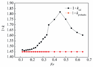
As shown in Table 2, the calculation results are almost the same in the low speed area. So this method that is used to calculate the form factor of high-speed catamaran has a high accuracy. As shown in Fig. 3, in low speed area, the form factor of high-speed catamaran is almost a constant. It can be calculated by normal method such as Prohaska method. But as the speed increase, the form factor also increases, then reach a peak value. Then the form factor decreases with the increase of speed.
| Table 2 2000-toners catamaran form factor |

|
Figure 3 Form factor changes along with the speed |
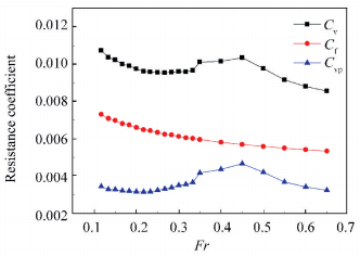
As shown in Fig. 4, viscous resistance coefficient increases when Fr > 0.25, and reaches a peak value at Fr=0.45 as the same as the form factor. Then the viscous resistance coefficient rapidly decreases. The equivalent plank frictional resistance coefficient is calculated by the 1957 ITTC friction formula. It is smooth decline as the Froud number increases. Thus, the viscos pressure resistance coefficient causes the change of form factor.

|
Figure 4 Viscous resistance coefficient |
This catamaran’s breadth increases from stem to stern smoothly. Therefore, there is not flow separation until the stern. There are two vortexes after each transom stern. The vortexes creates minus pressure after the transom stern. This causes the viscous pressure resistance.
Usually, the viscous resistance coefficient of the mono hull decreases when the Froud number increases. But the catamaran has two paralleled demi hulls, and the distance between the two demi-hull is small. This will cause the fluid flow velocity augmentation between the two demi hulls. When the Froud number increases, the velocity augmentation increases, and the pressure decreases after the stern decreases. Thus, the viscous pressure resistance rises. When the Fr < 0.5, the velocity augmentation is large relative to the catamaran speed. It is more effective to cause the viscous pressure resistance increases rapidly. As the Froud number further increases, the influence of velocity augmentation is lesser. And the growth of viscous pressure resistance slows down. Then the viscous pressure resistance coefficient decreases.
Therefore, in the high speed area, the form factor isn’t the same as the form factor in low speed area. It is not a constant. It is relative to the hull form, speed, and many other factors. It can’t be simply replaced by the form factor in low speed. We must calculate the form factor in the same speed to ensure the accuracy of estimation of actual ship resistance.
3 ConclusionsCurrently, researchers use two-dimension method or three-dimension method to convert the actual ship resistance. And in the three-dimension method, form factor is an important parameter.
Researchers usually use direct measurement method, Prohaska method and CFD method to estimate the form factor. These methods have their own advantage and disadvantage. They also establish equations to calculate the form factor of symmetrical hulls catamaran. CFD method has some advantage such as faster calculate speed, lower cost and easier model change.
This paper uses CFD method to estimate the form factor of a 2000-toners high-speed catamaran with asymmetrical demihulls. And the calculation results are verified by comparing with the experimental data.
In low speed area, the form factor of high-speed catamaran can be estimated by the Prohaska method. It is the same as the other ship. But as the speed increases, the form factor also increases, then reach a peak value. Then the form factor decreases with the increase of speed. Therefore, when the speed reaches high speed area, the form factor of high-speed catamaran can’t be calculated by the method used in low speed area. It must recalculate in this speed.
In conclusion, for the high-speed catamaran with asymmetrical demihulls, the form factor is not a constant value. It can’t be determined by the method used in low-speed area. It can’t be also calculated by the equations used to calculate the form factor of symmetrical hulls catamaran. We can use the CFD method to estimate the form factor. It will be more accurate and efficient. Then we can obtain a more accuracy actual ship resistance.
| [1] |
Antonio S I, David F G, Luis P R. Experimental assessment of interference resistance for a Series 60 catamaran in free and fixed trim-sinkage conditions.
Ocean Engineering, 2012 , 53 : 38-47.
DOI:10.1016/j.oceaneng.2012.06.008 ( 0) 0)
|
| [2] |
Riccardo B, Boris J, Stefano Z, et al. Experimental investigation of interference effects for high-speed catamarans.
Ocean Engineering, 2014 , 76 : 75-85.
DOI:10.1016/j.oceaneng.2013.12.003 ( 0) 0)
|
| [3] |
Li Guangnian, Chen Qingren, Xie Yonghe, et al. Computational research on wave-making resistance of asymmetric catamaran based on the panel method in time domain.
Chinese Journal of Hydrodynamics, 2013 , 3 (28) : 357-362.
( 0) 0)
|
| [4] |
Li Guangnian, Zhao Lianen, Chen Qingren, et al. Wave-making problem and optimal solution of piece hull arrangement for asymmetric catamaran.
Shipbuilding of China, 2013 , 4 (54) : 55-62.
( 0) 0)
|
| [5] |
Devrim B D. Reduction of demi-hull wave interference resistance in fast displacement catamarans utilizing an optimized centerbulb concept.
Ocean Engineering, 2014 , 91 : 227-234.
DOI:10.1016/j.oceaneng.2014.09.018 ( 0) 0)
|
| [6] |
Kaklis P, Papanikolaou A. The wave resistance of a catamaran with non-symmetric thin demihulls.
Proc 1st Nat Congress on Computational Mechanics Athens, 1992 : 927-936.
( 0) 0)
|
| [7] |
Papanikolaou A, Kaklis P, Spanos D.On the wave resistance of twin-hull floating bodies with non-symmetric demi-hulls. 11th International Workshop on Water Waves and Floating Bodies.Hamburg, 1996.
( 0) 0)
|
| [8] |
Wang Chenyi. Resistance characteristic of high-speed catamaran and its application.
Shipbuilding of China, 1994 (3) : 28-39.
( 0) 0)
|
| [9] |
Bruzzone D, Ferrando M, Gualeni P. Numerical and experimental investigation into resistance characteristics of symmetrical and unsymmetrical catamaran hull forms. Proc 5th Inter Symposium on High Speed Marine Vehicles. HSMV99, Capri, Italy, 1999.
( 0) 0)
|
| [10] |
Utama I K A P, Jamaluddin A, Aryawan W D. Experimental investigation into the drag interference of symmetrical and asymmetrical staggered and unstaggered catamarans.
The Journal of Ocean Technology, Peer-Reviewed Papers, Technology to the Wind, 2012 , 7 (1) : 47-58.
( 0) 0)
|
| [11] |
Antonio C, Damiano C. CFD Study of an innovative catamaran with asymmetrical hulls.
Advances in Water Resource and Protection, 2013 (1) : 1-10.
( 0) 0)
|
| [12] |
Zaraphonitis G, Spanos D, Papanikolaou A. Numerical and experimental study on the wave resistance of fast displacement asymmetric catamarans. Proc HIPER INT Conference.Hamburg, 2001.
( 0) 0)
|
| [13] |
Sheng Zhenbang, Liu Yingzhong. Shipping Principle: Volume 1.
Shanghai:Shanghai Jiao Tong University Press, 2003 : 224-232.
( 0) 0)
|
| [14] |
Hughes G. Friction and form resistance in turbulent flow and a proposed formulation for use in model and ship correlation.
Trans INA, 1957 , 96 : 314-376.
( 0) 0)
|
| [15] |
Eggers K W H, Sharma S D, Ward L W. An assessment of some experimental methods for determining the wave-making characteristics of a ship form.
Transactions of the Society of Naval Architects Marine Engineering, 1967 , 75 : 112-157.
( 0) 0)
|
| [16] |
Prohaska C W. A simple method for the evaluation of the form factor and the low speed wave resistance. Proceeding 11th International Towing Tank Conference.Tokyo, 1966.
( 0) 0)
|
| [17] |
International Towing Tank Conference. ITTC-recommended procedures and guidelines.Proceeding 12th International Towing Tank Conference.Rome, 1969.
( 0) 0)
|
| [18] |
Insel M, Molland A F. An investigation into the resistance components of high sp eed displacement catamarans.
RINA Transactions, 1992 , 134 : 1-20.
( 0) 0)
|
| [19] |
Liu Yingzhong, Zhang Huaixin, Li Yile, et al. Calculations of the ship performances and solving of RANS equations in the 21st Century.
Journal of Ship Mechanics, 2001 , 5 (5) : 66-84.
( 0) 0)
|
| [20] |
Chen Jingpu, Zhu Dexiang, He Shulong. Research on numerical prediction method for wave-making resistance of catamaran/trimaran.
Journal of Ship Mechanics, 2006 , 10 (2) : 23-29.
( 0) 0)
|
 2016, Vol. 23


