2. Department of Materials Science and Mechanical Engineering, Duke University, Durham 27705, USA
Double-helical planetary gear sets combine the advantages of general epicyclical gears and herringbone gears, and also are endowed with some unique features, such as, superior efficiency, compact volumes, strong carrying capacity and smooth movements[1-2].So these sets are particularly applied in the transmission fields of aeronautics, weapon equipments and shipbuilding industry et al, as a new effective structure of transmission, Sondkar and Kahraman[3-4] have developed its dynamic model, and examined the natural frequency and stability of dynamical load on each side of gear body, Sheng et al.[5] through numerical and analytical approaches conducted eigenvalue analysis and found three distinct vibration modes. Zhao et al.[6] have explored an analytical model for a two stages double-helical planetary gears to investigate the character of free vibration and also the relationship between natural frequency and vibration mode. From the previous literatures we know that mesh stiffness plays a significant role in load distribution and reliable performing in the dynamic transmission of gear pairs.Up to now, the studies that have addressed about the stiffness of these kinds of planetary gear sets are limited, and some researchers have focused on its dynamic response issues, but for the excitation element such as the stiffness usually be simplified as a rectangular wave form or Fourier series to investigate the dynamic characteristics and other vibration suppression[7], however, in reality, the total stiffness is complicated and various along with the time changing, one reason is that the tooth contact and separation between mating gears make the number of engaged tooth differently at every moment.
Concerns are that fluctuation of mesh stiffness would potentially induce the vibration and bring noises, to find out the regular mechanics of the stiffness, and the investigation is related to analyze the movement principle of the line of action.
Since the existence of nonlinear backlash and static transmission errors impose a strong effect on gear system, additionally, complicated structure and multiple meshes between S-P and R-P make the governing equation of motion involve more DOFs and coupled. Here the backlash is described by using a piecewise mathematic model as previous studies performed, space errors are coped within normal mesh deflections, and then the lumped-parameter model is effectively solved by associating with the combination of numerical approaches including Euler integral, Newton iteration method and Poincaré mapping. In this study, the primary purpose is trying to explore the accurate analytical modeling to investigate the time-varying mesh stiffness, and after that the comparison simulations of dynamical property are performed through comparing with sinusoidal waveform mesh stiffness.
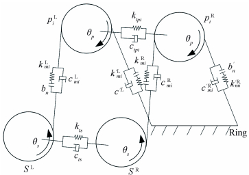
2 Physical Model and AssumptionsFig. 1 shows a dynamic model for double-helical planetary gear sets with three equally spaced planets; each planet possesses the same physical parameters and properties[8]. The input rotational torque acts on the sun, and ring is considered to be fixed on the gearbox which makes the circumferential deflection to be zero, and the carrier is constrained to rotate with the planets. Applying a spring and damping to the connection of mesh movement from sun-planet or ring-planet for the mesh gear pairs, backlashes are also described with spring and damping in Fig. 1.The two sides of the herringbone teeth are connected using an Euler beam element, which only includes spring and damping for the rotational motion, backlash is not included yet. kmi, kmi' denote the ith planet mesh stiffness with the sun and ring, respectively. Similarly, cmi, cmi' are the mesh damping of them; bnrepresents the backlash of the mesh gears; sL, sRdenote the left and right side of sun, and piL, piR are the left and right side of ith planet, respectively.
|
Figure 1 Dynamic model of double-helical planetary gear sets |
In Table 1 some example parameters of double-helical planetary gear sets are listed. Other parameters are number of planet is 3, and face width is 20 mm, and helix angle value on both sides are 16, and normal pressure angle is 20°, and meshing damping ratio is ξ=0.02, and rotational damping ratio is ζ=0.02.
| Table 1 Parameters of the example system |
To obtain the governing equations of motion for the system, some assumptions are employed as follows:
(a) The structure of the system is symmetric with the center of sun and each gear or carrier is considered to be rigid, and elastic deformations are negligible.
(b) Internal and external gear pairs are connected by spring and damping, and tooth frictions are not yet included.
(c) Line of action is on the plane of action, and mesh force is formulated by mesh relative displacement, and all the gear teeth profiles are perfect involutes.
It is assumed that the orientation of meshing line starts from sun to planet or planet to ring when establishing Eq. (1). Rotational resonance of ring is negligible due to fixing on the gearbox. Based on Newton's second law of motion and the moment of momentum theorem, the purely rotational dynamic equations with errors can be generally conducted via adopting lumped-parameter method, given as
| $\boldsymbol{M\ddot q + C\dot q + Kq = F}$ | (1) |
where q is a displacement vector; M and K are orthogonal matrices, represent mass and stiffness, respectively; F is a load vector,
| $M = \left[{\begin{array}{*{20}{c}} {I_s^L}&{}&{}&{}&{} \\ {}&{I_s^R}&{}&{}&{} \\ {}&{}&{I_{pi}^L}&{}&{} \\ {}&{}&{}&{I_{pi}^R}&{} \\ {}&{}&{}&{}&{{I_{ec}}} \end{array}} \right]$ | (2) |
| $\boldsymbol{M} = \left[{\begin{array}{*{20}{c}} {{k_{ts}}}&{}&{}&{}&{} \\ {}&{{k_{ts}}}&{}&{}&{} \\ {}&{}&{{k_{tpi}}}&{}&{} \\ {}&{}&{}&{{k_{tpi}}}&{} \\ {}&{}&{}&{}&0 \end{array}} \right]$ | (3) |
| $\boldsymbol{F} = \left[{\begin{array}{*{20}{c}} { - \sum\limits_{i = 1}^3 {\boldsymbol{F}_{spi}^{\text{L}}\cos \beta + \frac{{{T_0}}}{2}} } \\ { - \sum\limits_{i = 1}^3 {F_{spi}^{\text{R}}\cos \beta + \frac{{{T_0}}}{2}} } \\ {F_{spi}^{\text{L}}\cos \beta - F_{rpi}^{\text{L}}\cos \beta } \\ {F_{spi}^{\text{R}}\cos \beta - F_{rpi}^{\text{R}}\cos \beta } \\ {\sum\limits_{i = 1}^3 {\left( {F_{spi}^{\text{L}} + F_{spi}^{\text{R}} + F_{rpi}^{\text{L}} + F_{rpi}^{\text{R}}} \right)\cos \beta - {T_1}} } \end{array}} \right]$ | (4) |
where i=1, 2, 3; j=1, 2 is applied in these matrices.
In Eq. (4), T0, T1 are the input and output torque respectively; L and R represent left or right side. Ii, i=s, pi, ec denote moment of inertia for each lumped mass, and for carrier
Backlash is a primary nonlinear elements that causes unforeseeable perturbation or nonlinear phenomenon for gear dynamics, here, for a given tooth backlash 2bn, that is, bn=10 μm for each drive-side or back-side, nonlinear backlash function is generally expressed as
| $f\left( {x_i^j,{b_n}} \right) = \frac{{f'\left( {x_i^j,{b_n}} \right)}}{{{b_n}}} = \left\{ \begin{gathered} x_i^j - 1,\;\;\;\;\;x_i^j > 1 \hfill \\ 0,\;\;\;\;\;\;\;\;\;\;\;\left| {x_i^j} \right| \leqslant 1 \hfill \\ x_i^j + 1,\;\;\;\;\;x_i^j < - 1 \hfill \\ \end{gathered} \right.$ | (5) |
where f '(xij, bn) is an initial displacement function, j=L, R.
For double-helical planetary gear sets, the normal meshing forces FspiL, FspiR, FrpiL, FrpiR, generated along the line of action between S-P and R-P meshed are derived as
| $\left\{ \begin{gathered} F_{spi}^{\text{L}} = c_{mi}^{\text{L}}\dot \delta _{spi}^{\text{L}} + k_{mi}^{\text{L}}f\left( {\delta _{spi}^{\text{L}},{b_n}} \right) \hfill \\ F_{spi}^{\text{R}} = c_{mi}^{\text{R}}\dot \delta _{spi}^{\text{R}} + k_{mi}^{\text{R}}f\left( {\delta _{spi}^{\text{R}},{b_n}} \right) \hfill \\ \end{gathered} \right.$ | (6) |
| $\left\{ \begin{gathered} F_{rpi}^{\text{L}} = c_{mi}^{{\text{'L}}}\dot \delta _{rpi}^{\text{L}} + k_{mi}^{{\text{'L}}}f\left( {\delta _{rpi}^{\text{L}},{b_n}} \right) \hfill \\ F_{rpi}^{\text{R}} = c_{mi}^{{\text{'R}}}\dot \delta _{rpi}^{\text{R}} + k_{mi}^{{\text{'R}}}f\left( {\delta _{rpi}^{\text{R}},{b_n}} \right) \hfill \\ \end{gathered} \right.$ | (7) |
where δspiL, δspiR, δrpiL, δrpiR denote the mesh relative displacements for sun and ring on each side.
In the transmission of planetary gear sets, the rigid body motion is induced between gear pairs existing in Eq. (1). The mesh relative displacement expressions contains tooth space errors on sun and ring are
| $\left\{ \begin{gathered} \delta _{spi}^{\text{L}} = \left( {r_s^{\text{L}}\theta _s^{\text{L}} - r_{pi}^{\text{L}}\theta _{pi}^{\text{L}} - {r_c}{\theta _c}\cos {\alpha _p}} \right)\cos \beta - e_i^{\text{L}}\left( t \right) \hfill \\ \delta _{spi}^{\text{R}} = \left( {r_s^{\text{R}}\theta _s^{\text{R}} - r_{pi}^{\text{R}}\theta _{pi}^{\text{R}} - {r_c}{\theta _c}\cos {\alpha _p}} \right)\cos \beta - e_i^{\text{R}}\left( t \right) \hfill \\ \end{gathered} \right.$ | (8) |
| $\left\{ \begin{gathered} \delta _{rpi}^{\text{L}} = \left( {r_{pi}^{\text{L}}\theta _{pi}^{\text{L}} - {r_c}{\theta _c}\cos {\alpha _p}} \right)\cos \beta - e_i^{\text{L}}\left( t \right) \hfill \\ \delta _{rpi}^{\text{R}} = \left( {r_{pi}^{\text{R}}\theta _{pi}^{\text{R}} - {r_c}{\theta _c}\cos {\alpha _p}} \right)\cos \beta - e_i^{\text{R}}\left( t \right) \hfill \\ \end{gathered} \right.$ | (9) |
where rs, rpiare the base circle radii, respectively; rc is the radius of carrier;
Introducing another quantity
| $\begin{gathered} {{\tilde x}_s} = {r_s}\left( {\theta _s^{\text{L}} - \theta _s^{\text{R}}} \right) \\ {{\tilde x}_{pi}} = {r_{pi}}\left( {\theta _{pi}^{\text{L}} - \theta _{pi}^{\text{R}}} \right) \\ \end{gathered} $ | (10) |
Using Δ=(δspiL, δspiR, δrpiL, δrpiR,
| $\left\{ \begin{gathered} c_{mi}^{\text{L}} = c_{mi}^{\text{R}},c_{mi}^{'{\text{L}}} = c_{mi}^{'{\text{R}}} \hfill \\ k_{mi}^{\text{L}} = k_{mi}^{\text{R}},k_{mi}^{'{\text{L}}} = k_{mi}^{'{\text{R}}} \hfill \\ \end{gathered} \right.$ | (11) |
To improve numerical accuracy and computation time, one may introduce a new term
Therefore, the needed dimensionless quantities can be derived by terms
| $\begin{gathered} {{\tilde b}_n} = {b_n}/{{\hat b}_n} \\ k\left( \tau \right) = k\left( t \right),X\left( \tau \right) = x\left( t \right)/{{\hat b}_n} \\ \dot X\left( \tau \right) = \dot x\left( t \right)/\left( {{\omega _n}{{\hat b}_n}} \right),\ddot X\left( \tau \right) = \ddot x\left( t \right)/\left( {\omega _n^2{{\hat b}_n}} \right) \\ \end{gathered} $ |
With these dimensionless quantities, the equation sets with nonlinear clearance can be rewritten as a second order differential equations as Eq. (12), including 16 DOFs[9-11]
| $\boldsymbol{\ddot X + C\dot X + K}\left( t \right)f\left( \boldsymbol{X} \right) = \boldsymbol{F}$ | (12) |
where F, X, C, K(t) are all dimensionless vectors, and
| $\boldsymbol{X} = {\left[{{X_s},{X_{p1}},{X_{p2}},{X_{p3}},{X_{s11}},{X_{s21}},{X_{s31}},{X_{s12}},{X_{s22}},{X_{s32}},{X_{r11}},{X_{r21}},{X_{r22}},{X_{r32}}} \right]^{\text{T}}}$ |
One may define a dimensionless dynamic factor Kv to measure the perturbation that occurs on each mesh gear.
| $Kv = \frac{{\boldsymbol{K}\left( t \right)\left[{\boldsymbol{X}\left( t \right) - e\left( t \right)} \right] + \boldsymbol{C\dot X}\left( t \right)}}{{{f_n}}}$ | (13) |
where fn=T/(rbncos β) represents the normal static force; e(t) is dimensionless error.
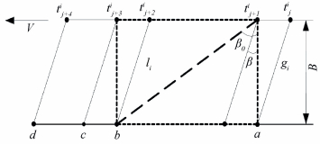
The participation teeth and length of action line are changing periodically with time in transfer motion, and the movement in Fig. 2 should be analyzed via the movement of meshing lines. On the basis of mean stiffness km and mean length of action line lm, the average stiffness coefficient can be calculated by ξ=km/lm, where km can be determined via a gear manual, and lm is engaged in one whole period. In terms of gear mesh theory, in the contact area (dotted rectangle area in Fig. 2), total action line length l can be obtained as a function of time t(Eq. (15)), Assuming meshing area moves from right to left at the speed of V=2πrb1n1, where rb1 represents base radius; n1 denotes rotational speed(r/m), accordingly, total number of participation teeth at certain moment is
| $N = {\text{INT}}\left( \varepsilon \right)$ | (14) |
where ε denotes the contact ratio; INT means round up to an integer.
|
Figure 2 Mesh movement diagram of gear tooth |
Total contact line length in action area at an instant time t can be calculated from
| $l\left( t \right) = \sum\limits_{n = 1}^N {{l_n}\left( t \right)} $ | (15) |
Finally, the total time-varying mesh stiffness is derived as
| $k\left( t \right) = \left\{ \begin{gathered} \xi {l_n}\left( t \right)\;\;\;\;{\text{if}}\;\;\;\;N = 1 \hfill \\ \sum\limits_{n = 1}^N {\xi {l_n}\left( t \right)\;\;\;\;{\text{if}}\;\;\;\;N > 1} \hfill \\ \end{gathered} \right.$ | (16) |
Here k(t) is a periodic function of time t.
In Fig. 2 the mesh motion area locates in gear pitch circle plane, and a, e represent the beginning and ending location point, respectively, from tji to tj+4i regarded as a circulation of whole mesh period; tji is the separation boundary point, where j denotes the calculating time beginning point, and i represents the helix angle type which can be classified into three cases, e.g. β < β0, β=β0 and β > β0, where β0 is set as a criterion value given as
| ${\beta _0} = \arctan \left( {\frac{{{\varepsilon _\alpha }{p_{bt}}}}{B}} \right)$ | (17) |
where εα is the transverse contact ratio; pbt is a transverse circular pitch; B denotes face width, other parameters are given and calculated as follows[12]:
| $ab = {\varepsilon _\alpha }{p_{bt}},cd = {p_{bt}},ad = \left( {N + 1} \right){p_{bt}}$ |
Based upon the analysis of motion shown in Fig. 2, the varying stiffness k(t) can be calculated through the following expressions in Eqs.(18)-(20).Where, these expressions are applied for a single tooth pair (s≡sin).
Case 1: β < β0
| ${k_i}\left( t \right) = \left\{ \begin{gathered} vt\xi {{\text{s}}^{ - 1}}\beta ,\;\;\;\;\;\;\;\;\;\;\;\;\;\;\;\;\;\;\;\;\;\;\;\;\;\;\;\;\;t \in \left[{t_0^1,t_1^1} \right] \hfill \\ B\xi {{\text{s}}^{ - 1}}\beta ,\;\;\;\;\;\;\;\;\;\;\;\;\;\;\;\;\;\;\;\;\;\;\;\;\;\;\;\;\;t \in \left[{t_1^1,t_2^1} \right] \hfill \\ \left( {B\tan \beta + {\varepsilon _\alpha }{P_{bt}} - vt} \right)\xi {{\text{s}}^{ - 1}}\beta ,\;\;t \in \left[{t_2^1,t_3^1} \right] \hfill \\ 0,\;\;\;\;\;\;\;\;\;\;\;\;\;\;\;\;\;\;\;\;\;\;\;\;\;\;\;\;\;\;\;\;\;\;\;\;\;\;t \in \left[{t_3^1,t_4^1} \right] \hfill \\ \end{gathered} \right.$ | (18) |
Case 2 : β=β0
| ${k_i}\left( t \right) = \left\{ \begin{gathered} vt\xi {{\text{s}}^{ - 1}}\beta ,\;\;\;\;\;\;\;\;\;\;\;\;\;\;\;\;\;\;\;\;\;\;\;\;\;\;\;\;t \in \left[{t_0^2,t_1^2} \right] \hfill \\ \left( {B\tan \beta + {\varepsilon _\alpha }{P_{bt}} - vt} \right)\xi {{\text{s}}^{ - 1}}\beta \;\;t \in \left[{t_1^2,t_2^2} \right] \hfill \\ 0,\;\;\;\;\;\;\;\;\;\;\;\;\;\;\;\;\;\;\;\;\;\;\;\;\;\;\;\;\;\;\;\;\;\;\;\;\;t \in \left[{t_2^2,t_3^2} \right] \hfill \\ \end{gathered} \right.$ | (19) |
Case 3: β>β0
| ${k_i}\left( t \right) = \left\{ \begin{gathered} vt\xi {{\text{s}}^{ - 1}}\beta ,\;\;\;\;\;\;\;\;\;\;\;\;\;\;\;\;\;\;\;\;\;\;\;\;\;\;\;\;t \in \left[{t_0^3,t_1^3} \right] \hfill \\ {\varepsilon _\alpha }{p_{bt}}\xi {{\text{s}}^{ - 1}}\beta ,\;\;\;\;\;\;\;\;\;\;\;\;\;\;\;\;\;\;\;\;\;\;\;t \in \left[{t_1^3,t_2^3} \right] \hfill \\ \left( {B\tan \beta + {\varepsilon _\alpha }{p_{bt}} - vt} \right)\xi {{\text{s}}^{ - 1}}\beta ,t \in \left[{t_2^3,t_3^3} \right] \hfill \\ 0,\;\;\;\;\;\;\;\;\;\;\;\;\;\;\;\;\;\;\;\;\;\;\;\;\;\;\;\;\;\;\;\;\;\;\;\;t \in \left[{t_3^3,t_4^3} \right] \hfill \\ \end{gathered} \right.$ | (20) |
Combining Eqs.(12) and (18), for S-P and R-P meshing transmission, the dimensionless stiffness of Ks and Kr yield as
| ${\boldsymbol{K_s}} = \frac{{\cos \beta }}{{\omega _n^2}}\left[{\begin{array}{*{20}{c}} {\frac{{\sum\limits_{i = 1}^3 {{k_{ij}}} }}{{{M_s}}} - \frac{{{k_{ij}}}}{{{M_p}}} - \frac{{\sum\limits_{i = 1}^3 {\sum\limits_{j = 1}^2 {{k_{ij}}} } }}{{{M_c}}}}&0 \\ 0&{\frac{{{k_{ij}}}}{{{M_p}}} - \frac{{\sum\limits_{i = 1}^3 {\sum\limits_{j = 1}^2 {{k_{ij}}} } }}{{{M_c}}}} \end{array}} \right]$ | (21) |
| ${\boldsymbol{K}_r} = \frac{{\cos \beta }}{{\omega _n^2}}\left[{\begin{array}{*{20}{c}} {\frac{{{k_{ij}}}}{{{M_p}}} - \frac{{\sum\limits_{i = 1}^3 {\sum\limits_{j = 1}^2 {{k_{ij}}} } }}{{{M_c}}}}&0 \\ 0 &{ - \frac{{{k_{ij}}}}{{{M_p}}} - \frac{{\sum\limits_{i = 1}^3 {\sum\limits_{j = 1}^2 {{k_{ij}}} } }}{{{M_c}}}} \end{array}} \right]$ | (22) |
where i is planet number; j denotes the left or right side; Mk, k=s, p, c represent the equivalent masses for sun, planet and carrier.
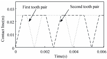
Fig. 3 reveals a movement of contact line while changing from one single tooth pair contact to double engagement, and it is nearly keeping double tooth pair contact at any time during one period. Meanwhile, there is no tooth separation happened on mesh tooth, and these behaviors also definitely guarantee a smooth driving motion.
|
Figure 3 Contact track of meshing tooth for Case 1 (β < β0) |
3 Solution Procedure
Eq. (12) is a nonlinear differential equation set, and its steady solution represents the mode of movement of the system. For obtaining accurate analysis, one may introduce a state vector[13]
| $\boldsymbol{u} = {\left\{ {{u_1},{u_2},{u_3},\cdots ,{u_{32}}} \right\}^{\text{T}}} = {\left\{ {{X_1},{{\dot X}_1},{X_2},{{\dot X}_2},\cdots ,{X_{16}},{{\dot X}_{16}}} \right\}^{\text{T}}}$ |
Then, Eq. (12) can be described as an non-autonomous system like
| $\frac{{{\text{d}}u}}{{{\text{d}}t}} = f\left( {t,{\omega _i},u} \right)$ | (23) |
Where ωi is a dimensionless excitation frequency.
With the vector of
| $\begin{gathered} u\left( {i + 1} \right) = u\left( i \right) + \int_{{t_0} + iT}^{{t_0} + \left( {i + 1} \right)T} {f\left( {t,{\omega _j},u} \right){\text{d}}t} ,\\ i = 1,2,3,\cdots ,n \\ \end{gathered} $ | (24) |
Because of the nonlinear excitation in Eq. (5) caused by backlash, the issue has changed to solve the problem of a nonlinear equation
| $G = \left( {\omega ,u} \right) = u - P\left( {\omega ,u} \right) = 0$ | (25) |
Giving an initial value ω0, in the light of the solution of Cauchy's problem for ordinary differential equation, Eq. (20) is transformed and calculated as
| $\left\{ \begin{gathered} \dot u\left( \omega \right) = - \left( {{{G'}_u}{{\left( {\omega ,u} \right)}^{ - 1}} \times {{G'}_\omega }\left( {\omega ,u} \right)} \right) \hfill \\ u = u\left( {{\omega _0}} \right) \hfill \\ \end{gathered} \right.$ | (26) |
The fixed point ui={Xi, Ẋi}T which constitute the solution trajectory on the phase space, the governing predictor formula of next point ui+1 is
| $u_{i + 1}^0 = {u_i} - {\left[{I - {{P'}_u}\left( {{\omega _i},{u_i}} \right)} \right]^{ - 1}} \times {{P'}_\omega }\left( {{\omega _i},{u_i}} \right) \times \omega $ | (27) |
Through the Newton iteration method, the modified equation of ui+1 can be rewritten as
| $\begin{gathered} u_{i + 1}^{j + 1} = {\left( {I - {{P'}_u}\left( {{\omega _i}.u_i^j} \right)} \right)^{ - 1}} \times \left[{P\left( {{\omega _i},u_i^j} \right) - } \right. \\ \left. {{{P'}_u}\left( {{\omega _i},u_i^j} \right)u_i^j} \right],j = 0,1,2,\cdots \\ \end{gathered} $ | (28) |
Combining Eqs. (28) and (23), Pu'(ωi, ui), Pω'(ωi, ui) can be solved by the following equations[14-15]
| $\left\{ \begin{gathered} \frac{{{\text{d}}{{P'}_u}\left( {{\omega _i}.{u_i}} \right)}}{{dt}} = {{f'}_i}\left( {t,{\omega _i},u} \right)P'{\left( {{\omega _i},{u_i}} \right)_u} \hfill \\ \frac{{{\text{d}}{{P'}_u}\left( {{\omega _i}.{u_i}} \right)}}{{dt}} = {{f'}_i}\left( {t,{\omega _i},u} \right)P'{\left( {{\omega _i},{u_i}} \right)_u} + {{P'}_\omega }\left( {t,{\omega _i},u} \right) \hfill \\ \end{gathered} \right.$ | (29) |
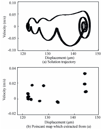
where ui={Xi, Ẋi}T is fixed points on a phase plane or Poincaré section, component elements relate to displacement and velocity. Employing arbitrary parameter like {X1, Ẋ1}T=0 as an initial iterative value for solving Eq. (23), the solution is plotted in Fig. 4. These phase plane plots are captured from steady status solution within T=25 periods and
|
Figure 4
Phase space with T=25, |
4 Dynamic Characteristic
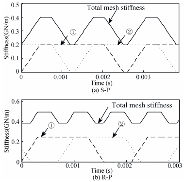
In Fig. 5, the dashed line ① represents the first mesh tooth pairs, and dotted line ② represents the second mesh tooth pairs, and solid line is the total mesh stiffness which gives the sum of line ① and line ② at the same instant, all of them are performing as TW, and correspond well with Fig. 3. With the rotation of mesh transmission, the mesh states are changing from one tooth pair to double or multi-tooth pairs.For the example system, a single tooth mesh period is 0.002 7 s and 0.001 6 s, with mesh stiffness amplitude is 0.41 GN/m and 0.49 GN/m for S-P and R-P, respectively.
|
Figure 5 Time-varying mesh stiffness of tooth pairs |
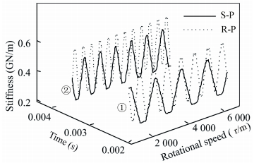
Fig. 6 shows the time-varying stiffness of single teeth under various rotational speed: ① denotes at t=0.002 3 s and ② denotes at t=0.003 8 s, both are trapezoid waveform. The stiffness are not synchronism at same time on S-P and R-P, and the reason is that different transmission ratio belongs to each mesh motion which would contribute to various velocity and period.
|
Figure 6 Time-varying stiffness of a single tooth |
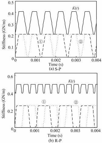
In Fig. 7, the periodical stiffness is plotted (K(t)) when rotational speed at n=6 000 r/m (① and ② refer to Fig. 5) as an example to analyze the dynamical characteristic under excitation of proposed approach, we also introduce a sinusoidal waveform periodicity mesh stiffness Ks(t) to be as a comparison, where Ks(t)=kssin(ωst+φ), ks is the mean mesh stiffness, here given as 0.32(GN/m) and 0.45(GN/m) for S-P and R-P meshes, respectively. ωs denotes mesh frequency; φ is initial phasing for each participate gears.Generally, mesh frequency depends on rotational speed and the number of gear tooth, and it has a significant effect on the excitation parameters, such as periodically varying stiffness, external load, transmission errors and so on.Fig. 7 belongs to the example of Case 1, where β0=48.5, β=16, it has an alternation in one or two teeth pairs of contact movement, and total mesh stiffness is calculated through the superposition of varying stiffness of engaged gear tooth, in addition, the tooth numbers are 23, 43, 109 for sun, planet and ring, respectively, which generates different mesh periods for them.
|
Figure 7 Meshing stiffness when n=6 000 r/m |
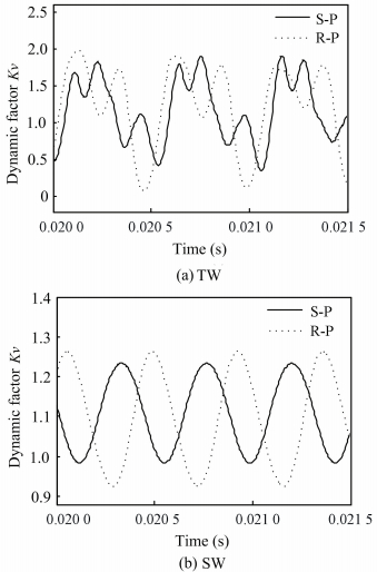
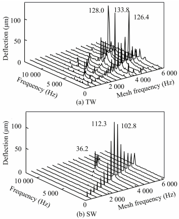
The dynamical factor gives an illustration about the perturbation happens on gears in Fig. 8, and it demonstrates large vibrations take place in TW because dynamical factors are 1.93 and 1.87, compares to 1.26, 1.23 in SW, respectively. One should realize that large dynamic factor can increase the risk of gear failure[16-20].Meanwhile, TW has complex sub-harmonics with response to stiffness excitation(see Fig. 10), and SW only yields a harmonic steady state dynamic response. One reason related might be considered is TW can be expanded in Fourier series with different mesh frequencies, e.g. iωm (i=1, 2, …, ∞). Furthermore, R-P mesh has greater values and fluctuation amplitude of dynamic factor over whole transmission period and conformed by both analyses, which means external mesh may contribute to a better stationarity.
|
Figure 8 Dynamic factor with time history |
|
Figure 10 FFT analysis for rotational deflection TW and SW |
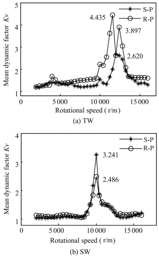
Fig. 9 compares the mean dynamic factors of TW and SW, and the comparison demonstrates the system under a stable movement when speed less than 10 000 r/m, and the global resonance occurs nearby 11 600r/m. The mean dynamic factor from TW is 1.51 compares to 1.28 on SW.However, in Fig. 9(b) a change happens on S-P, which has a larger vibration than R-P at the point of global perturbation.Fig. 10 confirms again about the perturbation of R-P is much stronger than it on S-P. Analyzing the relative deflection by FFT, three intensive resonance deflections are 133.8 μm, 128.0 μm and 126.4 μm, but in SW the three primary deflections are 112.3 μm, 102.8 μm and 36.2 μm.
|
Figure 9 Mean dynamic factor with various rotational speed |
5 Conclusions
On the basis of meshing movement principle of gear pairs, the mesh stiffness is calculated at each various moment through numerical analysis. One can develop three types of mesh stiffness formulas in term of the β. Then the new approach of case 1 is employed to examine the dynamical characters of double-helical planetary gear sets. Some main points include:
(1) The line of action and mesh stiffness both perform as a periodic trapezoid waveform while gear pairs are running, and mesh movement can be expressed using different formulations with time during one period.
(2) For the approaches of TW (β < β0) and SW, the mean dynamic factor is 1.51 and 1.28, respectively, both approaches demonstrate vibration happens on R-P is stronger than that on S-P.
(3) Rotational deflection under excitation of TW is greater and constituted with more harmonic frequencies, and global rotational deflection is 133.8 μm compares to 112.3 μm on SW.
| [1] |
Guo Yi, Parker R G. Dynamic modeling and analysis of a spur planetary gear involving tooth wedging and bearing clearance nonlinearity.
European Journal of Mechanics-A/Solids, 2010 , 29 (6) : 1022-1033.
DOI:10.1016/j.euromechsol.2010.05.001 ( 0) 0)
|
| [2] |
Ambarisha V K, Parker R G. Nonlinear dynamics of planetary gears using analytical and finite element models.
Journal of Sound and Vibration, 2007 , 302 (3) : 77-595.
DOI:10.1016/j.jsv.2006.11.028 ( 0) 0)
|
| [3] |
Sondkar P.
Dynamic Modeling of Double-Helical Planetary Gear Sets. Columbus, Ohio: The Ohio State University, 2012 : 3 -15.
( 0) 0)
|
| [4] |
Sondkar P, Kahraman A. A dynamic model of a double-helical planetary gear set.
Mechanism and Machine Theory, 2013 , 70 (3) : 157-174.
DOI:10.1016/j.mechmachtheory.2013.07.005 ( 0) 0)
|
| [5] |
Sheng Zhaohua, Tang Jinyuan, Chen Siyu, et al. Modal analysis of double-helical planetary gears with numerical and analytical approach.
Journal of Dynamic Systems, Measurement, and Control, 2015 , 137 (4) : 1-17.
( 0) 0)
|
| [6] |
Zhao Yongqiang, Li Guixian, Chang Shan, et al. Study on vibration characteristics of two stages double tooth planetary gear trains used in ship with high power.
Journal of Ship Mechanics, 2009 , 13 (4) : 621-627.
( 0) 0)
|
| [7] |
Cheon-Jae B, Parker R G. Analytical solution for the nonlinear dynamics of planetary gears.
Journal of Computational and Nonlinear Dynamics, 2011 , 6 (2) : 1-15.
DOI:10.1115/1.4002392 ( 0) 0)
|
| [8] |
Tugan E, Parker R G. An investigation of tooth mesh nonlinearity and partial contact loss in gear pairs using a lumped-parameter model.
Mechanism and Machine Theory, 2012 , 56 (1) : 28-51.
DOI:10.1016/j.mechmachtheory.2012.05.002 ( 0) 0)
|
| [9] |
Liu Gang, Parker R G. Nonlinear dynamics of idler gear systems.
Nonlinear Dynamics, 2008 , 53 (4) : 345-367.
DOI:10.1007/s11071-007-9317-z ( 0) 0)
|
| [10] |
Kahraman A. Planetary gear train dynamics.
Journal of Mechanical Design, 1994 , 116 (3) : 713-720.
DOI:10.1115/1.2919441 ( 0) 0)
|
| [11] |
Nevzat Özgüven H, Houser D R. Dynamic analysis of high speed gears by using loaded static transmission error.
Journal of Sound and Vibration, 1988 , 125 (1) : 71-83.
DOI:10.1016/0022-460X(88)90416-6 ( 0) 0)
|
| [12] |
Kwon H S, Kahraman A, Lee H K, et al. An automated design search for single and double-planet planetary gear sets.
Journal of Mechanical Design, 2014 , 136 (7) : 1-13.
DOI:10.1115/1.4026871 ( 0) 0)
|
| [13] |
Eritenel T, Parker R G. Modal properties of three-dimensional helical planetary gears.
Journal of Sound and Vibration, 2009 , 325 (1) : 397-420.
DOI:10.1016/j.jsv.2009.03.002 ( 0) 0)
|
| [14] |
Bahk C J, Parker R G. Analytical solution for the nonlinear dynamics of planetary gears.
Journal of Computational and Nonlinear Dynamics, 2011 , 6 (2) : 1-15.
DOI:10.1115/1.4002392 ( 0) 0)
|
| [15] |
Yang Zhen, Wang Sanmin, Fan Yesen. Nonlinear dynamic characteristic of split-torque gear transmission system.
Journal of Mechanical Engineering, 2008 , 44 (7) : 52-56.
DOI:10.3901/JME.2008.07.052 ( 0) 0)
|
| [16] |
Lin J, Parker R G. Mesh stiffness variation instabilities in two-stage gear systems.
Journal of Vibration and Acoustics, 2002 , 124 (1) : 68-76.
DOI:10.1115/1.1424889 ( 0) 0)
|
| [17] |
Qin Datong, Xiao Zhengming, Wang Jianhong. Dynamic characteristics of multi-stage planetary gears of shield tunneling machine based on planet mesh phasing analysis.
Journal of Mechanical Engineering, 2011 , 47 (23) : 20-29.
DOI:10.3901/JME.2011.23.020 ( 0) 0)
|
| [18] |
Chang-Jian Cai-Wan, Chang Shiuh-Ming. Bifurcation and chaos analysis of spur gear pair with and without nonlinear suspension.
Nonlinear Analysis: Real World Applications, 2011 , 12 (2) : 979-989.
DOI:10.1016/j.nonrwa.2010.08.021 ( 0) 0)
|
| [19] |
Sato K, Yamamoto S, Kawakami T. Bifurcation sets and chaotic states of a gear system subjected to harmonic excitation.
Computational Mechanics, 1991 , 7 (3) : 173-182.
DOI:10.1007/BF00369977 ( 0) 0)
|
| [20] |
Walha Lassâad, Fakhfakh Tahar, Haddar Mohamed. Nonlinear dynamics of a two-stage gear system with mesh stiffness fluctuation, bearing flexibility and backlash.
Mechanism and Machine Theory, 2009 , 44 (5) : 1058-1069.
DOI:10.1016/j.mechmachtheory.2008.05.008 ( 0) 0)
|
 2016, Vol. 23


