2. AVIC Chengdu Aircraft Industry (Group) Co. Ltd., Chengdu 610091, China
With the rapid development of aviation technology, the Hale UAV is getting more and more attention[1-3]. For the low temperature of UAV in the air will produce harmful effects to the fuel system and parts that it will make the water out of fuel or even icy, so that the fuel is frozen and the oil filter and filter are blocked[3-5]. The failure of the fuel system causes the fuel supply to the engine abnormal, thus the aircraft security is threatened[6-9]. There are many factors that affect the fuel temperature, including the length of the flight and the aerodynamic convection outside the fuel tank, air flow, solar radiation intensity, heat generated by heat pump inside the fuel tank, fuel quality and so on[10-11]. These factors determine the temperature distribution of fuel in the fuel tank. At present, the research of fuel oil temperature field[12] is mainly focused on the lighting protection of the fuel when the energy of large aircraft is managed integratedly, in order to make sure the maximum fuel temperature is lower than the minimum ignition temperature of the fuel. Lyu Yaguo[13], Kang Zhenye[14], Li Yanjiang[15] establish the temperature field method for aircraft fuel tank based on thermal network method. But these studies usually regard the fuel tank as a whole to ignore the influence of the fuel mass or the dynamic change of external environment on the temperature distribution of the fuel. And the research on the influence of low temperature environment of Hale on the temperature field of the fuel tank of the UAV is lacking.
This paper regards the fuel tank of Hale UAV as a study object. On the basis of considering the double dynamic changes of the fuel mass and the external thermal boundary, a mathematical model of transient coupled heat transfer, including the dynamic change of fuel quality, the internal heat transfer, the external aerodynamic convection and the radiation heat transfer, is established. The analysis of three dimensional unsteady heat transfer of the dynamic change of fuel and heat sink is developed by using external heat transfer as the third kind of thermal boundary and dealing with fuel consumption by combining thermal network method with hierarchical dynamic grid. Through the simulation calculation, the transient temperature distribution of the fuel tank under different flight conditions is obtained, and the influence of the fuel mass and the external thermal environment on the temperature field is analyzed.
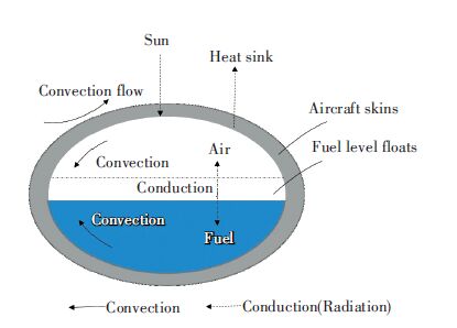
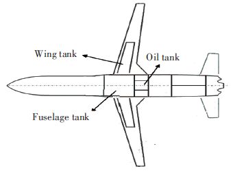
2 Mathematical ModelAccording to the geometric position, the fuel tank of the UAV is usually divided into the fuselage tank, wing tank, and oil tank and so on. And it is usually located in the surface of the aircraft skin. Due to the integral fuel tank as a closed system with complex structure, it is not only the existence of a variety of complex heat transfer and its quality will change with the time of flight, the center of gravity of the aircraft and other factors in flight conditions, so the temperature field is a comprehensive function formed by various factors and mechanisms. As for Hale UAV, the external fuel tank thermal environment need to consider that the outside surface skin of the fuel tank is heated or cooled due to aerodynamic effect and effected by solar radiation, space heat sink and other factors, when it need to fly in the high altitude atmosphere for a long time. The thermal environment inside the fuel tank is affected by the heat transfer between the fuel / air and the inner surface of the skin, the heat transfer between the fuel and equipment in the fuel tank, the residual mass of the fuel and other factors[16]. Internal and external heat transfer is realized by the interaction of the fuel tank surface. The integral thermal environment of the fuel tank of the UAV is formed by the coupling action, which can affect the transient temperature field distribution[17]. Fig. 1 shows the heat transfer mode which affects the overall temperature field on flight status.
|
Figure 1 Factors affecting the overall thermal environment of the fuel tank of the UAV |
The external high speed convective heat transfer, which is included in the external thermal environment of the fuel tank of the UAV, is a kind of convective heat transfer of unsteady turbulent that is compressible and viscous. So it is necessary to consider both the compression work and the viscous dissipation effect. The governing equations of this problem include mass conservation equations, momentum conservation equations and energy conservation equations, and the general form of the equation is[18]:
| $\frac{\partial \left( \rho \varphi \right)}{\partial \tau }+div\left( \rho U\varphi \right)=div({{\Gamma }_{\varphi }}grad~\varphi )+{{S}_{\varphi }}$ |
In the formula, ρ and v are the air current density and the velocity, φ is the universal variable, Γ and s are the generalized diffusion coefficient and the generalized source term respectively.
When the temperature field in the fuel tank is analyzed without considering the phase change of fuel oil, the energy conservation equation can be expressed as a unity:
| $\rho c\frac{\partial T}{\partial \tau }=\lambda {{\nabla }^{2}}T+\dot{Q}~$ |
In the formula, ρ, c and λ are density, specific heat and thermal conductivity; $\dot{Q}$ is an internal heat source term.
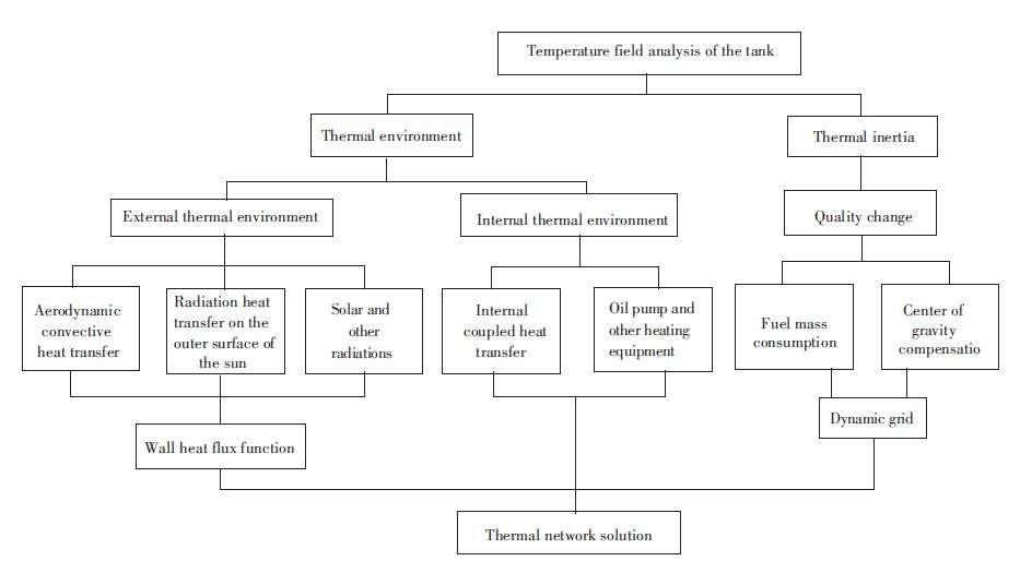
3 Numerical CalculationDue to the complexity of the thermal environment of the fuel tank in flight, it is difficult to realize the integration of direct simulation. According to the formation mechanism of the temperature field of the fuel tank, the factors that affect the temperature field of the tank can be divided into two types: thermal inertia and thermal environment, as shown in Fig. 2. The thermal inertia factor is due to the influence of changes in fuel quality on temperature field, mainly including dynamic fuel consumption and partial fuel tank compensation when considering the center of gravity, which realizes simulation analysis by hierarchical dynamic mesh modeling. Hot tank environmental factors include external thermal environment and internal thermal environment. With the wall heat flux of the skin as a floating thermal boundary condition[19], the integral coupling heat transfer process inside and outside the tank is divided into two relative independent heat transfer processes in the space that realize coupling through skin.
By the wall heat flux function, a large number of aerodynamic convection heat transfer simulation results are transformed to the convective heat transfer floating boundary conditions on the outer surface of the skin. At the same time, the radiation heat transfer between the skin and the external environment is expressed as a floating radiation boundary condition. The heat flux density function of an area unit Ai of the skin surface heated by the external thermal environment is:
qwo=δi, s·αs·qscosθi+εσ(Xi, eT44-T44)+qc(Ti, H, Ma)
In the formula, αs and ε are the solar absorption and infrared emissivity of the outer surface of the skin, and qs is the solar radiation heat flux density; θi is the angle between the surface normal and the light of the sun at Ai; δi is the direction of the surface unit Ai, when the Ai can be seen in the sun, δi=1, otherwise, δi=0; Xi, e is the angular coefficient of Ai to the earth; Te is the equivalent radiation temperature of the earth; σ is the Stefan-Boltzmann constant, qc(Ti, H, Ma) is aerodynamic convection heat transfer heat flux density between the plane and the surface air flow unit (heating is positive and cooling is negative), it is a function of Vi's temperature Ti, flight attitude H and flight Maher number Ma.
|
Figure 2 Schematic diagram of the factors affecting the overall temperature field of fuel tank |
As a closed system, the finite volume thermal network method is used to connect the equivalent thermal resistance in series and parallel connection, and the mutual radiation factor between the nodes is calculated by the Monte Carlo method. The thermal network equation[20-21] of the internal surface node Ai of the fuel tank is:
σ$\underset{\text{j=1}}{\overset{\text{NR}}{\mathop{\Sigma }}}\, $RD**(T44-T44)+$\underset{\text{k=1}}{\overset{\text{NR}}{\mathop{\Sigma }}}\, $Dk, i(Tk-Ti)+hiAi(Tf-Ti)=0
In the formula, RD** is the radiation transfer coefficient of the surface node Aj to the Ai;Dk, j is the heat transfer coefficient between the surface node Ai and the body node Vk; hi is the convective heat transfer coefficient of air flow in aircraft and surface node Ai; NR represents the number of radiative heat transfer nodes in the cabin; ND represents the number of heat conduction node in cabin. Dk, i=λeAi/δk, j represents the thermal conductivity; δk, j represents the distance between two points; λe represents the equivalent coefficient of thermal conductivity of materials.
The thermal networke quation[5] of body node Vi of fuel, air or equipment in fuel tank is:
mici$\frac{d{{t}_{i}}}{d\tau }$=$\underset{\text{k=1}}{\overset{\text{NR}}{\mathop{\Sigma }}}\, $Dk, i(Tk-Ti)+Qi
In the formula, (mi=ρiVi, Ti) represents the temperature of the node Vi; Qi indicates the thermal power of the node Vi, for the skin node and the Ai is the outer surface area of the skin body node that the Vi corresponds to.
Dealing with fuel consumption and analyzing internal heat transfer by using thermal network method combined with hierarchical dynamic grid. With the fuel consumption from top to bottom constantly changing the physical properties of the fuel grid, it simulates the fuel consumption and makes the air filled with fuel in the upper space through dynamic network. Dynamic simulation calculation is carried out under the condition of considering the convection heat transfer of the corresponding air layer.
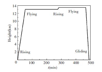
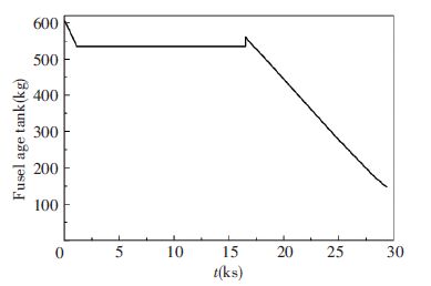
4 Example and Result AnalysisThe method mentioned above is used to simulate the temperature field of the fuel tank of a certain type of UAV. The tank arrangement is shown in Fig. 3. Fig. 4 shows the simulation of the flight envelope which includes two cruise altitudes of 13 km and 13.5 km, the maximum cruising speed is 0.527 Ma. According to the order of using the oil in the fuel tank and the phase of flight, Figs. 5 and 6 respectively give the quantitative relationship between time and fuel consumption of the fuselage and wing tank. In the simulation analysis, the air flow in the atmosphere is considered as the ideal gas according to the standard atmosphere. The initial temperature is analyzed according to the 288.15 K.
|
Figure 3 Schematic diagram of the fuel tank of the UAV |
|
Figure 4 Schematic diagram of flight envelope of the UAV |
|
Figure 5 Distribution of fuel consumption of fuselage tank |

|
Figure 6 Distribution of fuel consumption of wind tank |
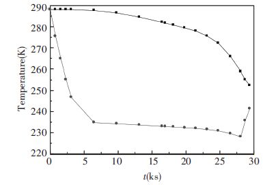
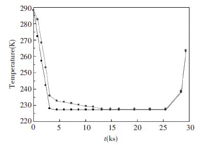
According to the simulation results of the whole flight envelope, it is found that the minimum temperature is usually located on the lower surface of the fuel tank skin, and the highest temperature is usually located near the center of the tank or the oil pump. Figs. 7 and 8 show the maximum temperature and the minimum temperature of the skin and fuel inside the body of the tank at different times. Analysis curve can be found that the overall temperature distribution of the fuel tank in the flight process with great changes in the flight situation. The fuel temperature change with time can be up to 60 K. The minimum fuel oil temperature is consistent with the minimum temperature distribution on the surface of the fuel tank. The temperature of the fuselage tank and the surface of the fuel tank decreases with the increase of the flight altitude. The surface of the fuel tank is generally presented with aerodynamic convection cooling effect, and the temperature at part of low temperature is decreased more significantly than that at high temperature. During the landing phase of glide, the minimum fuel temperature is 228 K and at this point the minimum temperature of the skin 225.7 K that is close to the solidification temperature of the fuel. During the initial phase of flight, the local maximum part of the fuel decreased slowly. But with the fuel consumption, it is affected by the natural convection of the air and the weakening of its thermal inertia and the temperature decreases gradually obviously. During the landing phase of the UAV, the minimum temperature of the fuel and the temperature of the surface skin of fuel tank are all increased with the effect of the rapid increase in the external temperature of the cabin, but the maximum temperature distribution of the fuel is still kept down.
|
Figure 7 Distribution curves of the highest and lowest temperature of the front fuselage tank |

|
Figure 8 Distribution curves of the highest and lowest temperature of the surface of the fuselage tank |
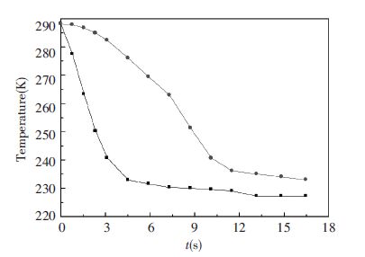
Figs. 9 and 10 show the simulation results of the temperature field of the skin of wing tank at different times. According to the fuel consumption order of the UAV and the fuel consumption rate of the wing fuel tank, it is found that the wing tank is completely exhausted when the time is 16 500 s and cruise altitude is 13 km. Compared with the fuselage tank, the contact area between the fuel oil and the inner surface of the skin of the wing tank is larger and the cooling effect of internal and external coupling heat transfer is also more obvious. In addition, the temperature of the fuel inside the wing tank is reduced faster than that inside the fuselage tank. And there is less heating equipment in the whole wing cabin, so the influence of the temperature field distribution on the skin surface is relatively weak. The skin surface basically reaches a uniform temperature distribution state after the wing is fully consumed.
|
Figure 9 Variation curves of the highest and lowest temperature of the surface skin of the wind tank |
|
Figure 10 Variation curves of the highest and lowest temperature of the section of the wind tank |
5 Conclusions
In this paper, the temperature field analysis and calculation model of the dynamic change of fuel quality, internal heat transfer, external aerodynamic convection and radiation heat transfer is established. The 3D transient temperature field analysis is realized by using external heat transfer as the third kind of thermal boundary and dealing with fuel consumption by combining thermal network method with hierarchical dynamic grid. The main conclusions are as follows:
1) A transient temperature field analysis method is established for the double dynamic change of the fuel mass and the external environment. This method can realize the transient temperature field analysis of the fuel tank during the flight.
2) For Hale UAV, the change of flight parameters, including flight height, flight speed and so on, will cause the change of the temperature of the fuel tank. The amplitude can reach 60 K, and the temperature is close to the solidification temperature of aviation fuel. There is a risk of solidification.
| [1] |
Barroso J, Renau J, Lozano A, et al. Experimental determination of the heat transfer coefficient for the optimal design of the cooling system of a PEM fuel cell placed inside the fuselage of an UAV.
Applied Thermal Engineering, 2015 , 89 : 1-10.
DOI:10.1016/j.applthermaleng.2015.06.003 ( 1) 1)
|
| [2] |
Zarco-Tejada P J, González-Dugo V, Berni J A J. Fluorescence, temperature and narrow-band indices acquired from a UAV platform for water stress detection using a micro-hyperspectral imager and a thermal camera.
Remote Sensing of Environment, 2012 , 117 (1) : 322-337.
DOI:10.1016/j.rse.2011.10.007 ( 1) 1)
|
| [3] |
Zarco-Tejada P J, Diaz-Varela R, Angileri V, et al. Tree height quantification using very high resolution imagery acquired from an unmanned aerial vehicle (UAV) and automatic 3D photo-reconstruction methods.
European Journal of Agronomy, 2014 , 55 (2) : 89-99.
DOI:10.1016/j.eja.2014.01.004 ( 2) 2)
|
| [4] |
Miguel N D, Cebolla R O, Acosta B, et al. Compressed hydrogen tanks for on-board application: Thermal behaviour during cycling.
International Journal of Hydrogen Energy, 2015 , 40 (19) : 6449-6458.
DOI:10.1016/j.ijhydene.2015.03.035 ( 1) 1)
|
| [5] |
Delhomme B, Lanzini A, Ortigoza-Villalba G A, et al. Coupling and thermal integration of a solid oxide fuel cell with a magnesium hydride tank.
International Journal of Hydrogen Energy, 2013 , 38 (11) : 4740-4747.
DOI:10.1016/j.ijhydene.2013.01.140 ( 2) 2)
|
| [6] |
Miana M, Cantín O, Millán C, et al. Enhancement of the thermal design of bitumen emulsion tanks by Scale Analysis, CFD models and experimental tests.
Applied Energy, 2011 , 88 (11) : 4106-4112.
DOI:10.1016/j.apenergy.2011.03.026 ( 1) 1)
|
| [7] |
Ivashov S, Razevig V, Vasiliev I, et al. Holographic subsurface radar for diagnostics of cryogenic fuel tank thermal insulation of space vehicles.
NDT & E International, 2015 , 69 : 48-54.
DOI:10.1016/j.ndteint.2014.10.002 ( 1) 1)
|
| [8] |
Biencinto M, Bayón R, Rojas E, et al. Simulation and assessment of operation strategies for solar thermal power plants with a thermocline storage tank.
Solar Energy, 2014 , 103 (6) : 456-472.
DOI:10.1016/j.solener.2014.02.037 ( 1) 1)
|
| [9] |
Vincent J, Carella J M, Cisilino A P. Thermal analysis of the girth weld of an elastomeric diaphragm tank.
Journal of Materials Processing Technology, 2014 , 214 (2) : 428-435.
DOI:10.1016/j.jmatprotec.2013.09.004 ( 1) 1)
|
| [10] |
Zhong Shi-Sheng.
Prediction of aircraft engine health condition parameters based on ensemble ELM. Journal of Harbin Institute of Technology(New Series). 2013 : 7 -11.
( 1) 1)
|
| [11] |
Ai Qing, Liu Hua, Xia Xinlin, et al. Influence of high temperature composite insulation structure on its transient thermal characteristics.
CIESC Journal, 2014 , 65 (z1) : 371-376.
( 1) 1)
|
| [12] |
Bu Xianbiao, Tan Yufei. Thermal impact on storage tank of natural gas vehicle during discharge process.
Journal of Harbin Institute of Technology(New Series), 2010 , 17 (2) : 234-238.
( 1) 1)
|
| [13] |
Lyu Yaguo, Ren Guozhe, Liu Zhenxia, et al. Study on thermal analysis of aircraft fuel tank.
Propulsion Technology, 2015 , 36 (1) : 61-67.
( 1) 1)
|
| [14] |
Kang Zhenye, Liu Zhenxia, Ren Guozhe, et al. Simulation and calculation of fuel oil temperature in aircraft fuel tank based on MATLAB/Simulink.
Propulsion Technology, 2014 , 35 (1) : 62-69.
( 1) 1)
|
| [15] |
Li Yanjiang, Feng Zhenzhou, Liu Yongshou. Study on simulation and analysis of aircraft fuel system.
Journal of Xi'an Technological University, 2008 , 28 (4) : 401-405.
( 1) 1)
|
| [16] |
Pan A G, Wang J B, Zhang X J, et al. Experimental research of electronic devices thermal control using metallic phase change materials.
Journal of Harbin Institute of Technology(New Series), 2014 , 21 (2) : 113-121.
( 1) 1)
|
| [17] |
Ai Qing, Xia Xinlin, Ren Depeng. Transient temperature field analysis of the infrared radiation of aircraft skin.
Journal of Infrared and Millimeter Waves, 2007 , 26 (3) : 174-177.
( 1) 1)
|
| [18] |
Liu Y, Li G, Jiang L. A new improved solution to thermal network problem in heat-transfer analysis of spacecraft.
Aerospace Science and Technology, 2010 , 14 (4) : 225-234.
DOI:10.1016/j.ast.2009.12.001 ( 1) 1)
|
| [19] |
Ai Qing, Xia Xinlin, Tang Yao. The wall heat flux function for solving coupled heat transfer of aircraft skin.
Journal of Engineering Thermophysics, 2006 , 27 (4) : 635-637.
DOI:10.3321/j.issn:0253-231X.2006.04.030 ( 1) 1)
|
| [20] |
Wang Yinghao.
Transient Thermal Analysis of Multi Body Structures under Complex Boundary Conditions. Harbin: Harbin Institute of Technology, 2008 .
( 1) 1)
|
| [21] |
Ai Qing, Sun Fengxian, Xia Xinlin. Mobile-region monte carlo method for thermal radiative transfer.
Journal of Engineering Thermophysics, 2012 (10) : 1781-1784.
( 1) 1)
|
 2016, Vol. 23


