The hydraulic turbine governing system (HTGS) is a complex, nonlinear, multivariable, time-varying and non-minimum phase system[1-2], whose parameters change significantly as operating point changes, especially in large perturbation. An approximate linearization[3-4] model is often employed to describe the HTGS in small perturbation, while some nonlinear factors, such as dead-zone, output saturation and clearance in feedback system of the servomotor, would have obviously effect on HTGS[5-7] and should be taken into consideration according to research needs. Taking the output saturation of distributing valve for example, the position of main distributing valve may reach saturation when the perturbation approaches 10% of total output, which in turn affects dynamic behaviors of HTGS. Bifurcation analysis has been used to evaluate how the control system alters the steady-state dynamics in Refs.[8-10]. In addition, existence of such bifurcation phenomena and other rich dynamics, such as synchronization, symmetric bifurcation and chaos that appear in many nonlinear dynamical systems[11-12]are also studied in detail based on nonlinear models[13-15], and have made a lot of meaningful research results[16-17].
Bifurcation phenomena in HTGS have been considered as a cause of decreased availability and reduced stability[18-19] for a long time. These studies are instrumental in identifying and documenting the oscillations in hydraulic generating units, however, the reports are scarce on the possible existence, the direction of Hopf bifurcation in HTGS and its effects on the oscillatory behaviors. In fact, with the head and capacity increasing of unit set, self-excited oscillations and unstable oscillation problems, caused by hydraulic, mechanical, electrical and other factors, have become prominent increasingly. Nonlinear dynamic analysis and stability control have been one of the issues that people are most concerned about in the hydropower station operation already[20-22].
Motivated by the above discussions, the existence of Hopf bifurcation and its direction for a PID controller type speed governing system with saturation nonlinearity are investigated by using a small perturbation model in this paper. Simulations on both sides of bifurcation are presented by numerical calculations. Theory analysis and simulation results suggest the PID parameters located in limit cycle part should be avoided when a PID or a gain-scheduling PID scheme is used in the system. Otherwise, Hopf bifurcation or undesirable oscillation that is detrimental for the safe and stable operation of unit set may occur in the governing system.
2 Nonlinear Mathematical Model of HTGSThe closed-loop system is often regarded as a serial one with a linear part and a nonlinear part[23-24]when studying the systems with saturation nonlinearity. A PID governing system with saturation is employed in this paper, as shown in Fig. 1, where xr is the reference input, x and y are output of the speed and position of the servomotor, respectively, and mr is the load perturbation. Transfer function of the PID type governor is described as follows:
| ${{G}_{PID}}\left( s \right)={{K}_{p}}+({{K}_{i}}/s)+{{K}_{d}}s$ | (1) |

|
Figure 1 Structure of HTGS with saturation |
where Kp, Ki and Kd are the proportional, integral and differential gains, respectively. An approximate linearization model Gt(s) is adopted for the hydro turbine in small perturbation in this paper, that:
| ${{G}_{t}}\left( s \right)={{e}_{y}}(1-e{{T}_{w}}s)/(1+{{e}_{qh}}{{T}_{w}}s)$ | (2) |
where Gt(s) denotes the transfer function from servomotor of the guide vane to hydro turbine moment in which a rigid water column model and a linear model of piping systems are employed[25-26], e=eqyeh/ey-eqh.
The dynamic equation for turbine output torque mt can be described as:
| ${{{\dot{m}}}_{t}}=\frac{1}{{{e}_{qh}}{{T}_{w}}}\left[ -{{m}_{t}}+{{e}_{y}}y-\frac{e{{e}_{y}}}{{{T}_{w}}{{T}_{y}}}\left( u-y \right) \right]$ | (3) |
where ey is a partial derivative of turbine torque with respect to the guide vane; eqy is a partial derivative of the flow with respect to the guide vane; eqh is a partial derivative of the flow with respect to the head; eh is a partial derivative of turbine torque with respect to the head; Tw is water inertia time constant of a pressure guide-water system.
A synchronous generator Gg(s), connected to an infinite bus through a transmission line, is regarded as the target system. The second-order nonlinear model can be expressed by:
| $~\left\{ \begin{align} & \delta ={{\omega }_{0}}\omega \\ & \dot{\omega }=({{m}_{t}}-{{m}_{e}}-K\omega )/{{T}_{ab}} \\ \end{align} \right.$ | (4) |
where δ, ω, K and Tab denote the rotor angle, relative speed deviation, damping coefficient, sum of the machine starting time and load time constants, respectively. Electromagnetic torque of generator me is equal to its electromagnetic power Pe:
| ${{m}_{e}}~=\text{ }{{P}_{e}}$ |
Electromagnetic power Pe can be described with the following equation:
| ${{P}_{e}}=\frac{E{{\prime }_{q}}{{V}_{s}}}{x\prime dx\Sigma }\text{sin }\!\!~\!\!\text{ }\delta +\frac{{{V}_{s}}^{2}}{2}\frac{x\prime dx\Sigma -xqx\Sigma }{x\prime dx\Sigma xqx\Sigma }\text{sin}~2\delta $ | (5) |
Where the effects of speed deviations, damping coefficient andtorque variations are all included in the analysis of the generator dynamic characteristics[27]. And
| $\left\{ \begin{align} & x\prime dx\Sigma =x{{\prime }_{d}}+{{x}_{T}}+0.5{{x}_{L}} \\ & xqx\Sigma ={{x}_{q}}+{{x}_{T}}+0.5{{x}_{L}} \\ \end{align} \right.$ | (6) |
where E′q and x′qxΣ are the transient electric potential and synchronous reactance of q-axis, respectively; Vs is the infinite bus voltage and x′dxΣ is the transient reactance of d-axis; x′d and xq are the direct axis transient reactance and quadrature axis reactance; xT and xL are the transformer short circuit reactance and the transmission line reactance, respectively.
Eqs.(4) -(6) are the simplified second-order generator model based on approximate linearization turbine model, which has been considered to be sufficient and widely applied in stability and dynamic quality analysis of HTGS from a power system operation view point. Higher order nonlinear generator model can be employed according to research needs.
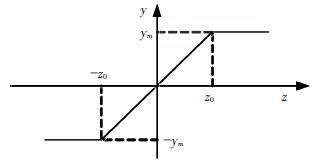
Saturation in actuators is inevitable in many feedback control systems. Therefore, output saturation of the servomotor position in a HTGS will be taken into consideration in this paper. The nonlinear block of saturation can be expressed by u=N(z), N(z) represents the nonlinear function of the saturation part. To get the nonlinear equation of a closed-loop system, a new variable z is defined as follows:
| $z={{K}_{p}}+({{K}_{i}}/s)+{{K}_{d}}s$ |
Then u=N(Kp +Ki /s+Kds). The nonlinear block in Fig. 2 is given by:
| $u=N\left( z \right)=({{y}_{m}}/2{{z}_{0}})(\left| z+{{z}_{0}} \right|-\left| z-{{z}_{0}} \right|)$ | (7) |
|
Figure 2 Nonlinear block of saturation |
For convenience, set ym=1 and z0=1. Then Eq.(7) can be expressed by:
| $\begin{align} & u=N\left( z \right)=\frac{1}{2}(|{{K}_{p}}+\frac{{{K}_{i}}}{s}+{{K}_{d}}s+1|- \\ & |{{K}_{p}}+\frac{{{K}_{i}}}{s}+{{K}_{d}}s-1|) \\ \end{align}$ | (8) |
Based on the discussions above, the four-dimensional differential equations that coupled each individual part of HTGS with saturation nonlinearity can be written as:
| $\left\{ \begin{align} & \dot{\delta }={{\omega }_{0}}\omega \\ & \dot{\omega }=\frac{1}{{{T}_{ab}}}({{m}_{t}}-K\omega -\frac{E{{\prime }_{q}}{{V}_{s}}}{x\prime dx\Sigma }\text{sin}~\delta -\frac{{{V}_{s}}^{2}}{2}\frac{x\prime dx\Sigma -xqx\Sigma }{x\prime dx\Sigma xqx\Sigma }\text{sin}~2\delta ) \\ & {{{\dot{m}}}_{t}}=\frac{1}{{{e}_{qh}}{{T}_{w}}}(-{{m}_{t}}+{{e}_{y}}y-\frac{e{{e}_{y}}{{T}_{w}}}{{{T}_{y}}}\dot{y}) \\ & \begin{array}{*{35}{l}} \dot{y}=\frac{1}{{{T}_{y}}}(\frac{1}{2}(\left| {{K}_{p}}+\frac{{{K}_{i}}}{s}+{{K}_{d}}s+1 \right|- \\ \left| {{K}_{p}}+{{K}_{i}}s+{{K}_{d}}s-1 \right|)-y)\left( 9 \right) \\ \end{array} \\ \end{align} \right.$ | (9) |
Eq.(9) is the water-electro-mechanical coupled nonlinear model of HTGS that integrates turbine model of rigid water hammer, water pipes linear model[28], PID type governor model and second-order generator model. The complex nonlinear nature problem within the system could be revealed much better by Eq.(9) compared to a linear one.
Numerical calculations of Eq.(9) can be carried out by using the Function ode45 in MATLAB to investigate the nonlinear dynamical behaviors of HTGS, e.g., Hopf bifurcation point, direction of Hopf bifurcation, bifurcation surface of PID parameters and time domain response waveforms of state variables. Time step is set to be 0.01 in the study. In addition, the Matcont software is also used to calculate the supercritical Hopf bifurcation points in the study.
3 The Existence of Dynamic Hopf Bifurcation and Its Direction 3.1 Existence Determination of Hopf BifurcationThe existence conditions of the Hopf bifurcation for a four-dimensional nonlinear system, such as Eq.(9) above, should satisfy the following theorem according to the Hopf bifurcation theory of nonlinear dynamical systems. Meanwhile, the values collection of Hopf bifurcation can be also determined when Hopf occurs[29].
Theorem: the Jacobi matrix characteristic polynomial for a nonlinear system y=F(x, v) at equilibrium point (x=0, x∈R4) can be defined as:
| $f(\lambda ,\text{ }v)=~{{\lambda }^{4}}+{{p}_{3}}\left( v \right){{\lambda }^{3}}+{{p}_{2}}\left( v \right){{\lambda }^{2}}+{{p}_{1}}\left( v \right)\lambda +{{p}_{0}}\left( v \right)$ | (10) |
where v∈R1 is the bifurcation parameter. The following conditions (a) and (b) hold if v=0:
(a) The coefficient pi > 0 (i = 0, 1, 2, 3) , and
| ${{p}_{3}}{{p}_{2}}{{p}_{1}}={{p}_{3}}^{2}{{p}_{0}}+{{p}_{1}}^{2}$ | (11) |
| $\left( b \right)\text{ }p{{\prime }_{0}}\ne (\frac{{{p}_{3}}}{{{p}_{0}}{{p}_{1}}}-\frac{{{p}_{1}}}{{{p}_{3}}})\frac{{{p}_{3}}p{{\prime }_{1}}-p{{\prime }_{3}}{{p}_{1}}}{{{p}_{3}}^{2}}+\frac{p{{\prime }_{2}}{{p}_{1}}}{{{p}_{3}}}$ | (12) |
where *′= d* /dv, pi(i=1, 2, 3) is the coefficient of the characteristic equation. When | v | is sufficiently small, Hopf bifurcation exists in one side of v=0, and the period of limit cycle can be described as follows:
| $T=2\pi \sqrt{({{p}_{3}}/{{p}_{1}})}$ | (13) |
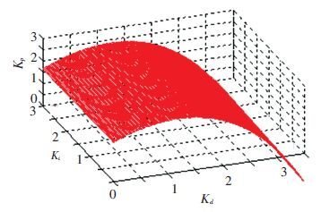
Eqs.(10) -(13) are the direct conditions for existence of Hopf bifurcation for a four-dimensional nonlinear system. All the points on the surface that determined by Eq.(11) are Hopf bifurcation critical points that would lead to the amplitude oscillation of the unit, as shown in Fig. 3. For example, the system will suffer a periodic oscillation phenomenon, namely Hopf bifurcation, if conditions (a) and (b) are satisfied, i.e., the PID parameters are on the critical surface of Fig. 3. Structure stability of the system will change dramatically, leading to the system structure instability and complex nonlinear oscillations when the PID parameters located in the unstable area.
|
Figure 3 Bifurcation surface of Kp, Ki, Kd |
PID parameters instability region that lies beneath the surface can guarantee the HTGS working in a safe and stable state; correspondingly, the instability region that called limit cycle is located in certain area above surface. PID parameters on the surface or in limit cycle should be avoided when a PID or a gain-scheduling PID scheme is used. Otherwise, Hopf bifurcation or undesirable oscillations may occur. Fig. 3 can be applied to investigate the relationship between the PID parameters and system stability.
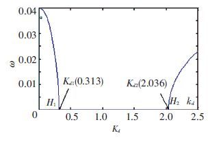
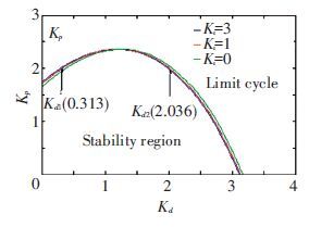
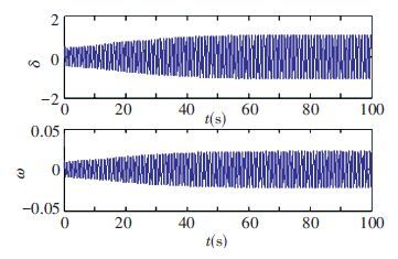
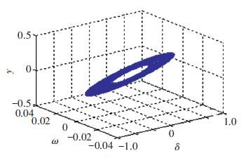
Taking vd=Kd-Kd* or vp=Kp-Kp* as the bifurcation parameter, when |v| is sufficiently small, the sustained periodic oscillation phenomenon will take place according to the theorem. For example, let Ki*=1, Kp*=2, the bifurcation parameter Kd can be calculated to be Kd1*=0.313 and Kd2*=2.036, respectively, as shown in Fig. 4. Kd1* and Kd2* can be also obtained through the intersection values between the ordinate line (Kp=2) and the boundary curve (Ki=1) , as shown in Fig. 5. All the points that in limit cycle, for example, Ki=1, Kd=2, Kp=2.5 (vp>0) , would lead to the undesirable diffused oscillation, as shown in Figs. 6 and 7. Furthermore, the stable and unstable PID parameters can be obtained much easier through Fig. 5 when compared with Fig. 3.
|
Figure 4 Bifurcation diagram of rotor speed ω |
|
Figure 5 Curves of bifurcation points with Ki=0, 1, 3 |
|
Figure 6 Time waveforms of δ and ω with Ki=1, Kd=0.313, Kp=2.32 |
|
Figure 7 Phase orbit of δ, ω and y |
Fig. 4 shows the bifurcation diagram of speed ω calculated by the Matcont software. Two bifurcation points of Kd are presented in Fig. 4 when Kp=2, Ki=1, i.e. Kd1*=0.313 and Kd2*=2.036. Speed ω converge to equilibrium point 0 when Kd1<Kd<Kd2 and to stable limit cycle when Kd>Kd2 or Kd<Kd1. What’s more, ω will converge to stable limit cycle when 0 <Kd<Kd1* or Kd> Kd2*.
The stability of system can also be analyzed from perspective of mathematics. The properties and Jacobi matrix roots for different values of Kd are presented in Table 1. The Jacobi matrix has two conjugate complex roots with negative real parts when the system is in the stable domain (Kd1*<Kd<Kd2*), and then the system tends to be stable (equilibrium point); when the parameters are the critical bifurcation point (Kd1*, Kd2*), Jacobi matrix has two negative real roots and two pure imaginary conjugate complex roots, the system is in center of bifurcation; When Kd<Kd1* or Kd>Kd2*, the matrix has two conjugate complex roots, a negative real part one and a positive real part one, and system will converge to stable limit cycle at this time.
| Table 1 Changes of system properties with the bifurcation parameter Kd |
Theoretical analysis of Table 1 can be considered as an explanation for the phenomenon that occurs in Fig. 4. Dynamic behaviors of nonlinear systems in critical bifurcation point can be seen from Fig. 4 and Table 1 clearly. Moreover, it can be obtained that when Kd is far away from two bifurcation points and near to middle place between Kd1* and Kd2*, the system is more stable and the convergence rate is much quicker. In practical applications, values of Kd should be between two critical places and the farther the better. Excessive and tedious calculations can be avoided by using the theorem above. However, the theorem does not give the direction of bifurcation; further study will be discussed in Section 3.2.
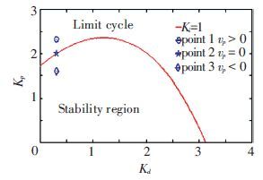
Point 1 (Ki=1, Kd=0.313, Kp=2.32, vp>0) , point 2 (Ki=1, Kd=0.313, Kp=2.0, vp=0) and point 3 (Ki=1, Kd=0.313, Kp=1.6, vp<0) are three typical points in Fig. 8, respectively. Direction of Hopf bifurcation can be told from these points, which will be verified by the simulation results in Figs. 6-7 and Figs. 9-12.
|
Figure 8 Curves of bifurcation and three typical points |
3.2 Direction of Hopf Bifurcation
Researches in Section 3.1 can be applied to calculate the existence conditions of Hopf bifurcation, but direction and stability of bifurcation need to be further studied. Eq.(10) will have two negative real roots and two pure imaginary conjugate complex roots if condition (a) holds:
| ${{\lambda }_{k}}=\pm i{{\omega }_{0}}=\pm \text{i}\sqrt{({{p}_{1}}/{{p}_{3}})},\text{ }k=1,\text{ }2$ | (14) |
Taking vp=Kp-Kp* as bifurcation parameter; then the application of Eq.(10) yields:
| $\frac{d{{\lambda }_{k}}}{dv}{{|}_{v=0}}=\frac{1.56{{\omega }_{0}}^{2}\mp 2.78i{{\omega }_{0}}}{(3{{p}_{3}}{{\omega }_{0}}^{2}-{{p}_{1}})\pm 2i{{\omega }_{0}}(2{{\omega }_{0}}^{2}-{{p}_{2}})}$ | (15) |
The real part of Eq.(15) is:
| $\begin{align} & a\prime \left( {{v}_{0}} \right)=\text{Re}\frac{d{{\lambda }_{k}}}{dv}{{|}_{v=0}}= \\ & {{\omega }_{0}}^{2}\frac{1.56(3{{p}_{3}}{{\omega }_{0}}^{2}-{{p}_{1}})\pm 5.56{{\omega }_{0}}^{2}(2{{\omega }_{0}}^{2}-{{p}_{2}})}{{{(3{{p}_{3}}{{\omega }_{0}}^{2}-{{p}_{1}})}^{2}}+4{{\omega }_{0}}^{2}{{(2{{\omega }_{0}}^{2}-{{p}_{2}})}^{2}}}, \\ & k=1,\text{ }2\text{ } \\ \end{align}$ | (16) |
Where the denominator and numerator of the right side in Eq.(16) are positive values according to condition (a) and Eq.(17) , i.e., Re (dλk/dv) |v=0>0, (k=1, 2) , the Hopf bifurcation points that presented in Table 1 is supercritical. The equilibrium point of the system is a stable focus if v<0; Correspondingly, a periodic movement will be generated from the equilibrium point when v>0 (taking point 1 vp of Fig. 8 for example), in this case, a stable limit cycle will appear in the system and a diffused sustained oscillation of output can be observed, as shown in Figs. 6 and 7.
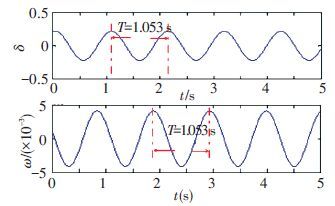
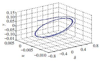
The corresponding sustained oscillation curves of δ, ω and the system stable focuses at point 2, where vp=0, are presented in Figs. 9 and 10, respectively, in which the oscillation period is T≈1.053 s, that is consistent with the calculation result from Eq.(13) . The governing system makes a periodic oscillation instead of converging to equilibrium point 0 and further reveals that the system is not able to be stable.
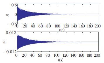
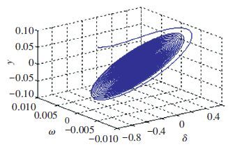
The curves for δ, ω and stable focus at point 3, where vp<0, are shown in Figs. 11 and 12. The system state variables will finally converge to the equilibrium point 0. Moreover, the system is more likely to converge to an equilibrium point 0 quickly by making the PID parameter apart from the Hopf bifurcation points, the further the better.
|
Figure 9 Time waveforms of δ and ω with Ki=1, Kd=0.313, Kp=2.0 |
|
Figure 10 Phase orbit of δ, ω and y |
|
Figure 11 Time waveforms of δ and ω with Ki=1, Kd=0.313, Kp=1.6 |
|
Figure 12 Phase orbit of δ, ω and y |
Analysis and simulation above show that a supercritical Hopf bifurcation exists in HTGS. Figs. 6-7 and Figs. 9-12 illustrate the direction of Hopf bifurcation and its characteristic: Hopf bifurcation is supercritical when the real part Re(dλk/dv)|v=0>0, (i=1, 2) , and the equilibrium point of the system is a stable focus if v<0, and when v>0 a periodic movement will occur.
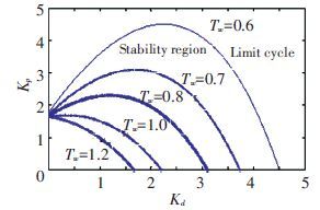
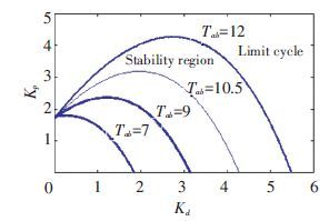
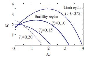
4 Effect of Different Parameters on StabilityCurves in Fig. 5 represent Kp=Kp* for different values of Kd when Ki=0, 1, 3, respectively. A stable limit cycle will appear in HTGS according to conditions (a) and (b). When Kp and Kd locate in the limit cycle part of Fig. 5, a sustained oscillation with certain period will appear in the system, which is not generally expected in the flied operation. Consequently, suitable parameters should be selected carefully so that the PID parameters can be located in stable region in Fig. 5 to guarantee the unit set operating in a stable state. Similarly, curves in Figs. 13-16 represent Kp* for different values of Kd when Tw, Tab, Ty and K changes, respectively.
|
Figure 13 Curves of bifurcation points with different Tw, Ki=1 |
|
Figure 14 Curves of bifurcation points with different Tab, Ki=1 |
|
Figure 15 Curves of bifurcation points with different Ty, Ki=1 |

|
Figure 16 Curves of bifurcation points with different K, Ki=1 |
The stability regions have decreased radically when Tw and Ty increase, indicating that Tw and Ty are the detrimental factors that lead to instability of system, consistent with the conclusions of other scholars. Meanwhile, stability regions expand with Tab and K increasing, which can help the system converge to the equilibrium point quickly.
5 Example and Numerical SimulationsParameters of the HTGS that works under certain operating conditions are setting as follows: ω0=314, Tw=0.8 s, Tab=9.0 s, Ty=0.1 s, K=2, E′q=1.35, Vs=1, x′dxΣ=1.15, x′qxΣ=1.474, eqh =0.5, ey =1.0, e=0.7, respectively. Jacobi matrix characteristic polynomial coefficients pi of the system Jacobi matrix characteristic polynomial coefficients pi at equilibrium point (0, 0, 0, 0) are obtained as follows:
| $\left\{ \begin{array}{*{35}{l}} {{p}_{3}}=12.72-1.56*{{K}_{d}} \\ {{p}_{2}}=2.78*{{K}_{d}}-1.56*{{K}_{p}}+62.07 \\ {{p}_{1}}=2.78*{{K}_{p}}-1.56*{{K}_{i}}+434.15 \\ {{p}_{0}}=2.78*{{K}_{i}}+857.2 \\ \end{array} \right.$ | (17) |
Three-parameters implicit polynomial is obtained after substituting Eq.(17) into Eq.(11) and a space bifurcation surface can be carried out, as shown in Fig. 3. Bifurcation diagram for ω is illustrated in Fig. 4. Curve of bifurcation points is shown in Fig. 8, in which three typical points for direction of Hopf bifurcation are included. The limit cycles for the three typical points of Fig. 8 are shown in Figs. 7, 10 and 12, and the corresponding oscillation curves of δ and ω are shown in Figs. 6, 9 and 11. Figs. 13-16 in part 4 present the curves that represent Kp* for different values of Kd when Ki=1, where the system parameters Tw, Tab, Ty, K change, respectively.
6 ConclusionsA fully coupled nonlinear mathematical model for a PID governing system with saturation has been developed in this paper. Extensive investigations of the Hopf bifurcation behaviors of an example HTGS under various conditions were conducted using the proposed model. Unexpected limit cycle oscillation in HTGS was clearly illustrated from various perspectives when PID parameters meet certain conditions. The study also revealed that stability of the system was closely related to system parameters such as Tw, Tab, indicating the parameters should be carefully selected to guarantee safe and stable operation of hydro turbine unit. The work in this paper suggests that Hopf bifurcation can be considered as one of the possible reasons for sustained oscillations phenomenon commonly seen in HTGS. Simulation results validate the theoretical analysis. This paper presents a novel analysis approach to research the stability of HTGS.
| [1] |
Fang H Q, Dlakavu N. Basic modeling and simulation tool for analysis of hydraulic transients in hydroelectric power plants. IEEE Trans. Energy Convers, 2008, 23(3): 834-841.
( 0) 0)
|
| [2] |
Shakya S R, Shrestha R M. Transport sector electrification in a hydropower resource rich developing country: energy security, environmental and climate change co-benefits.
Energy for Sustainable Development, 2011 , 15 (6) : 147-159.
( 0) 0)
|
| [3] |
Kishor N, Saini R P, Singh S P. A review on hydropower plant models and control. Renewable Sustainable Energy Rev., 2007, 11(5): 776-796.
( 0) 0)
|
| [4] |
Pennacchi P, Chatterton S, Vania A. Modeling of the dynamic response of a Francis turbine.
Mechanical Systems and Signal Processing, 2012 (29) : 107-119.
( 0) 0)
|
| [5] |
Ling D J, Shen Z Y. Bifurcation analysis of hydro-turbine governing system with saturation nonlinearity.
Journal of Hydroelectric Engineering, 2007 , 26 (12) : 126-131.
( 0) 0)
|
| [6] |
Li Junyi, Chen Qijuan. Fractional order controller designing with firefly algorithm and parameter optimization for Hydroturbine governing system. Mathematical Problems in Engineering, 2015. Article ID 825608, http://dx.doi.org/10.1155/2015/825608.
( 0) 0)
|
| [7] |
Xu Beibei, Wang Feifei, Chen Diyi. Hamiltonian modeling of multi-hydro-turbine governing systems with sharing common penstock and dynamic analyses under shock load.
Energy Conversion and Management, 2016 , 108 (15) : 478-487.
( 0) 0)
|
| [8] |
Gill Stephen J, Lowenberg Mark H, Neild Simon A. Nonlinear dynamics of aircraft controller characteristics outside the standard flight envelope.
Journal of Guidance, Control and Dynamic, 2015 , 38 (12) : 2031-2038.
( 0) 0)
|
| [9] |
Berchio E, Ferrero A, Gazzola F. Structural instability of nonlinear plates modelling suspension bridges: Mathematical answers to some long-standing questions.
Nonlinear Analysis-Real World Application, 2016 , 28 (12) : 91-125.
( 0) 0)
|
| [10] |
Bochicchio I, Giorgi C, Vuk E. Asymptotic dynamics of nonlinear coupled suspension bridge equation.
Journal of Mathmatics Analysis and Application, 2013 , 402 (1) : 319-333.
DOI:10.1016/j.jmaa.2013.01.036 ( 0) 0)
|
| [11] |
Song Y, Tadé M O, Zhang T. Bifurcation analysis and spatio-temporal patterns of nonlinear oscillations in a delayed neural network with unidirectional coupling.
Nonlinearity, 2009 , 22 (5) : 975-1001.
DOI:10.1088/0951-7715/22/5/004 ( 0) 0)
|
| [12] |
Hu H, Liu L, Mao J. Multiple nonlinear oscillations in a D3×D3 symmetrical coupled system of identical cells with delays. Abstract and Applied Analysis, 2013. Article ID 417678.
( 0) 0)
|
| [13] |
Inayat-Hussain J I. Nonlinear dynamics of a statically misaligned flexible rotor in active magnetic bearings.
Communications in Nonlinear Science and Numerical Simulation, 2010 , 15 (3) : 764-777.
DOI:10.1016/j.cnsns.2009.04.020 ( 0) 0)
|
| [14] |
Widyan M S. On the effect of AVR gain on bifurcations of subsynchronous resonance in power systems.
Electrical Power and Energy Systems, 2010 , 32 (6) : 656-663.
DOI:10.1016/j.ijepes.2009.11.024 ( 0) 0)
|
| [15] |
Prakash, M, Balasubramaniam, P. Bifurcation analysis of macrophages infection model with delayed immune response.
Communications in Nonlinear Science and Numerical Simulation, 2016 (35) : 1-16.
DOI:10.1016/j.cnsns.2015.10.012 ( 0) 0)
|
| [16] |
Lerm A P, Silva A S. Avoiding Hopf bifurcations in power systems via set-points tuning.
IEEE Transactions on Power Systems, 2004 , 19 (2) : 1076-1084.
DOI:10.1109/TPWRS.2004.825827 ( 0) 0)
|
| [17] |
Pulgar-Painemal Hector A, Galvez-Cubillos Ricardo I. Limit-induced bifurcation by wind farm voltage supervisory control.
Electric Power Systems Research, 2013 (10) : 122-128.
DOI:10.1016/j.epsr.2013.05.010 ( 0) 0)
|
| [18] |
Moradi H, Alasty A, Vossoughi G. Nonlinear dynamics and control of bifurcation to regulate the performance of a boiler-turbine unit.
Energy Conversion and Management, 2013 (68) : 105-113.
DOI:10.1016/j.enconman.2012.12.027 ( 0) 0)
|
| [19] |
Liu Xianlin, Liu Chu. Eigenanalysis of oscillatory instability of a Hydropower plant including water conduit dynamics.
IEEE Transactions on Power Systems, 2007 , 22 (2) : 675-681.
DOI:10.1109/TPWRS.2007.89515 ( 0) 0)
|
| [20] |
Chen Diyi, Ding Cong. Nonlinear dynamical analysis of hydro-turbine governing system with a surge tank.
Applied Mathematical Modelling, 2013 , 37 (14) : 7611-7623.
DOI:10.1016/j.apm.2013.01.047 ( 0) 0)
|
| [21] |
Chen Zhihuan, Yuan Xiaohui, Ji Bin, et al. Design of a fractional order PID controller for hydraulic turbine regulating system using chaotic non-dominated sorting genetic algorithm II.
Energy Conversion and Management, 2014 (84) : 390-404.
DOI:10.1016/j.enconman.2014.04.052 ( 0) 0)
|
| [22] |
Sahu R K, Panda S, Rout U K. DE optimized parallel 2-DOF PID controller for load frequency control of power system with governor dead-band nonlinearity.
International Journal of Electrical Power & Energy Systems, 2013 (49) : 19-33.
DOI:10.1016/j.ijepes.2012.12.009 ( 0) 0)
|
| [23] |
Chen Diyi, Ding Cong. Nonlinear dynamic analysis for a Francis hydro-turbine governing system and its control.
Journal of the Franklin Institute, 2014 , 351 (9) : 4596-4618.
DOI:10.1016/j.jfranklin.2014.07.002 ( 0) 0)
|
| [24] |
Li Junyi, Chen Qijuan. Nonlinear dynamical analysis of hydraulic turbine governing systems with non-elastic water hammer effect . Journal of Applied Mathematics, 2015.Article ID 412578, doi:10.1155/2014/412578.
( 0) 0)
|
| [25] |
Li W, Vanfretti L, Chompobutrgool Y. Development and implementation of hydro turbine and governor models in a free and open source software package.
Simulation Modelling Practice and Theory, 2012 (24) : 84-102.
DOI:10.1016/j.simpat.2012.02.005 ( 0) 0)
|
| [26] |
Salhi I, Doubabi S, Essounbouli N. Application of multi-model control with fuzzy switching to a micro hydro-electrical power plant.
Renewable Energy, 2010 , 35 (9) : 2071-2079.
DOI:10.1016/j.renene.2010.02.008 ( 0) 0)
|
| [27] |
Li C S, Zhou J Z. Parameters identification of hydraulic turbine governing system using improved gravitational search algorithm.
Energy Conversion and Management, 2011 , 52 (1) : 374-381.
DOI:10.1016/j.enconman.2010.07.012 ( 0) 0)
|
| [28] |
Martínez-Lucas G, Sarasúa J I, Sánchez-Fernández J A, et al. Power frequency control of hydropower plants with long penstocks in isolated systems with wind generation.
Renewable Energy, 2015 (83) : 245-255.
DOI:10.1016/j.renene.2015.04.032 ( 0) 0)
|
| [29] |
Li M Y, Shu H. Joint effects of mitosis and intracellular delay on viral dynamics: two-parameter bifurcation analysis.
Journal of Mathematical Biology, 2012 , 64 (6) : 1005-1020.
DOI:10.1007/s00285-011-0436-2 ( 0) 0)
|
 2016, Vol. 23


