2. University of Chinese Academy of Sciences, Beijing 100049, China ;
3. Institute of Geology and Geophysics, Chinese Academy of Sciences, Beijing 100029, China
With the development in space optical technology, the requirements on the resolution ratio and field range of aerospace mapping cameras are increasingly high. Due to the ease of designing off-axis TMA optical systems with long focal length and large field of view, and their being clear of occlusion, until recently they have been widely applied to aerospace mapping cameras[1-4]. Cartosat-1 the two-line array mapping camera sent by India in 2005[5-7], PRISM the three-line array mapping camera developed by Japan in 2006[8], and TH-1 the first tridimensional mapping camera of China all adopted off-axis TMA optical system[9-10]. However, during the on-orbit imaging period of an aerospace camera, the earth’s rotation, satellite attitude maneuver and flutter along with other factors lead to mismatch between the image motion velocity of image points on the focal plane and the TDICCD charge packet transfer velocity[11-13]. This effect is named image motion, which may result in image blur and decreased MTF[14-15]. Moreover, image motion has more impacts on off-axis TMA aerospace mapping cameras. Thus, image motion compensation according to image motion velocity field during on-orbit imaging period is indispensable for obtaining high-quality mapping images[16-17].
Abroad, the United States had carried out a comprehensive work on image motion compensation technology for a long time, the system was mainly divided into two parts: the first part was called image motion compensation (IMC), which compensated image motion caused by satellite orbit movement and attitude changes by adjusting the line transfer period of TDICCD; the second part was called scan mirror motion compensation (MMC), which built a mathematical model to estimate the attitude jitter trend within one line period, thereby driving the scanning mirror movement to accomplish its compensation. Ingo et al. of German Aerospace Center used micro-mechanical devices, set up a rotating mirror in front of the objective lens and achieved the image motion compensation of the space camera optical system. Japan’s MTSAT weather satellite adopted spatial resampling technique to scan imaging, which reduced the interference among the loads and to some degree resolved the image motion compensation issue. Although foreign image motion compensation models and technologies are in very strict secrecy, but the fact that the reconnaissance satellites resolution in recent years has reached 0.5 m or less reflects that the image motion compensation technology of some foreign military powers has reached an advanced level.
Domestically, Wang et al.[18] derived a calculation model of aerospace image motion velocity vector under sub-satellite point imaging from a set of seven coordinate systems that transforms ground objects to focal plane points. However, the fact that the earth is a spheroid was not considered. Wang et al.[19] deduced an analytical expression of image motion velocity through analyses on the image formation and dynamic imaging problems of apparent kinetic spatial objects with smooth curved surface. The influence of off-axis angle on image motion velocity field model was ignored, limiting the use of the expression to coaxial optical systems only. Wu et al.[20]established an equivalent and simplified model of off-axis TMA two-line array mapping cameras according to a geometric method and obtained a computational formula of image motion velocity and drift angles of nadir-view and backward-view cameras, whereas the influence of satellite attitude stability on the model was neglected and only focal plane center point was considered when analyzing the scheme for matching image motion velocity and drift angle[21-22].
This paper proposes a new method of image motion velocity field modeling. With the off-axis angle in consideration, an analytical expression of image motion velocity of off-axis TMA three-line array aerospace mapping camera is deduced, based on which an analysis of the distribution characteristics of focal plane image motion velocity field of forward-view camera, nadir-view camera and backward-view camera is given. Besides, the optimization schemes for image motion velocity matching and drift angle matching are formulated according to the simulation results, providing reliable basis for on-orbit image motion compensation of aerospace mapping cameras.
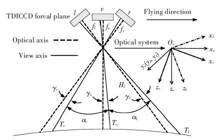
2 Image Motion Velocity Field Model of Three-line Array Mapping Cameras 2.1 Imaging Principle of CamerasThe imaging part of a three-line array mapping camera consists of three groups of linear array CCD sensor, which are mutually parallel and vertical to flight direction. During a space flight, the three groups of CCD continuously scan and photograph ground objects, obtaining images of three overlapped flight strips of a same ground object at different field of view positions, which further constitutes stereoscopic images[3, 10, 22]. Fig. 1 shows the imaging principle of off-axis TMA three-line array mapping cameras. l, v and r represent the forward-view camera, the nadir-view camera and the backward-view camera respectively, and fl , fv and fr denote the focal lengths of the three cameras accordingly. The light sent from the ground object Tv (Tl, Tr) transmits along the view axis and forms an image point when reaching the focal plane. The included angle between the optical axis which is vertical to the CCD focal plane and the view axis is called off-axis angle and is denoted as γv(γl, γr). αl represents the intersection angle between the forward-view camera and nadir-view cameras, while αr denotes the intersection angle between the backward-view and nadir-view cameras. The work in this paper aims mainly at developing a three-lens three-line array camera with high base to height ratio and mapping precision.
|
Figure 1 Imaging principle of off-axis TMA three-line array mapping camera |
2.2 Definition of Coordinate Systems
Nine coordinate systems from ground object to focal plane are established according to the characteristics of a three-line array mapping camera, and the definition of the coordinates are as follows (all right-handed coordinate systems).
The geocentric equatorial coordinate system Oe-xIyIzI (I coordinate for short): the origin is at the earth’s core Oe; OexI is in the equatorial plane and points to the vernal equinox; OezI is vertical to the equatorial plane and points to the north pole.
The satellite orbital coordinate system Os-xoyozo(o coordinate for short): the origin is at the satellite’s center of mass Os; Osxo is in the satellite orbit plane and points to the satellite motion direction; Oszo points to the center of mass Oe.
The satellite coordinate system Os-xbybzb(b coordinate for short): it coincides with o coordinate without attitude motion; the roll, pitch and yaw attitude angles of b coordinate relative to o coordinate are φ, θ, ψ, with attitude angle velocity of
Coordinate system Oc-xvyvzv of the nadir-view camera (v coordinate for short): the origin is the principal point of the optical system Oc; Ocxvyv plane is the objective plane of nadir-view camera; Oczv points to the ground object along the optical axis.
Coordinate system Oc-xlylzl of the forward-view camera (l coordinate for short): the origin is the same as that of v coordinate; Ocxlyl plane is the objective plane of the forward-view camera; Oczl points to the ground object along the optical axis.
Coordinate system Oc-xryrzr of the backward-view camera (r coordinate for short): the origin is the same as that of v coordinate; Ocxryr is the objective plane of the backward-view camera; Oczr points to the ground object along the optical axis.
Coordinate system Op-xpypzp of the nadir-view camera’s focal plane (p coordinate for short): the origin is at the center of the nadir-view camera’s focal plane Op; Opxp is along the TDI direction and parallel to Ocxv; Opyp is vertical to the TDI direction; Opzp is the normal of the focal plane.
Coordinate system Om-xmymzm of the forward-view camera’s focal plane (m coordinate for short): the origin is at the center of the forward-view camera’s focal plane Om; Omxm is along the TDI direction and parallel to Ocxl; Omym is vertical to the TDI direction; Omzm is the normal of the focal plane.
Coordinate system On-xnynzn of the backward-view camera’s focal plane (n coordinate for short): the origin is at the center of the backward-view camera’s focal plane On; Onxn is along the TDI direction and parallel to Ocxr; Onyn is vertical to the TDI direction; Onzn is the normal of the focal plane.
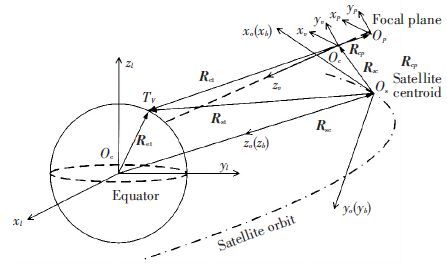
In this paper, the nadir-view camera is taken as an example of deduction since the modeling principle of image motion velocity field of forward-view, nadir-view and backward-view cameras are similar. The imaging vector correlation of the nadir-view camera is shown in Fig. 2. The sun-synchronous circular orbit is adopted to simulate the satellite orbit and the WGS84 ellipsoidal model is adopted for the earth. Related physical variables include, the semi-major axis ae, the semi-minor axis be, the geocentric distance of the satellite orbit r, the orbit inclination i, the orbit ascending node right ascension Ω, the argument of latitude u(in the orbital plane, the geocentric angle between the satellite and the ascending node).
|
Figure 2 Imaging vector correlation of the nadir-view camera |
2.3 Coordinate System Transformation and Vector Deduction
Primitive rotation. The primitive rotation matrices that describe the coordinate system rotating around the x, y or z axis by an angle of ε are given by
| $~\left\{ \begin{matrix} {{C}_{x}}\left( \varepsilon \right)=\left[ \begin{matrix} 1 & 0 & 0 \\ 0 & cos\varepsilon ~ & \varepsilon \\ 0 & -sin\varepsilon & \varepsilon \\ \end{matrix} \right] \\ {{C}_{y}}\left( \varepsilon \right)=\left[ \begin{matrix} cos~\varepsilon & 0 & -sin~\varepsilon \\ 0 & 1 & 0 \\ sin~\varepsilon & 0 & cos~\varepsilon \\ \end{matrix} \right] \\ {{C}_{z}}\left( \varepsilon \right)=\left[ \begin{matrix} ~~cos~\varepsilon & sin~\varepsilon & 0 \\ -sin~\varepsilon & cos~\varepsilon & 0 \\ 0 & 0 & 1 \\ \end{matrix} \right] \\ \end{matrix} \right.$ | (1) |
Coordinate translation. If the coordinate of the origin O′ after translation is [k, m, n]T in the original coordinate system, then the coordinate system after translation is
| ${{\left[ x\prime ,\text{ }y\prime ,\text{ }z\prime \right]}^{T}}={{\left[ x,\text{ }y,\text{ }z \right]}^{T}}-{{\left[ k,\text{ }m,\text{ }n \right]}^{T}}$ | (2) |
The vector coordinate transformation from I coordinate to o coordinate is shown by Eq.(3) . This equation is obtained via three consecutive primitive rotations, among which AoI denotes the transformation matrix from I coordinate to o coordinate.
| ${{A}_{oI}}={{C}_{y}}(-u-\frac{\pi }{2})\text{ }{{C}_{x}}(i-\frac{\pi }{2})\text{ }{{C}_{z}}\left( \Omega \right)$ | (3) |
Eq.(4) represents the coordinate transformation from o coordinate to b coordinate, where Abo is the transformation matrix from o coordinate to b coordinate.
| ${{A}_{bo}}={{C}_{z}}\left( \psi \right){{C}_{y}}\left( \theta \right){{C}_{x}}\left( \varphi \right)$ | (4) |
From the vector correlation shown in Fig. 2 we possess Eq.(5) , where Rst denotes the vector from the satellite’s center of mass Os to ground object Tv, Ret and Res are the vectors from the earth’s core Oe to Tv and Os respectively.
| ${{R}_{st}}={{R}_{et}}-{{R}_{es}}$ | (5) |
Rst in o coordinate can be expressed as Eq.(6) , where RetI is the expression of Ret in I coordinate, and Reso is the expression of Res in o coordinate.
| ${{R}_{es}}^{o}={{A}_{oI}}{{R}_{et}}^{I}-{{R}_{es}}^{o}$ | (6) |
As shown in Eq.(7) , Rct is the vector from the principal point of optical system Oc to ground object Tv, while Rsc is the vector from Os to Oc.
| ${{R}_{ct}}={{R}_{st}}-{{R}_{sc}}$ | (7) |
The expression of Rct in v coordinate is given by Eq.(8) , where Rstb and Rstb are the expressions of Rst and Rscin b coordinate respectively, and Mvb denotes the assembling matrix of the nadir-view camera.
| ${{R}_{ct}}^{v}={{M}_{vb}}({{R}_{st}}^{b}-{{R}_{st}}^{b})$ | (8) |
According to the vector correlation from Fig. 2, we have Eq.(9) , where q is the corresponding image point of ground object Tv in the nadir-view camera’s focal plane; Rpqp denotes the vector from the focal plane centerOp to q in p coordinate; Rctv is the expression of the vector from Oc to Op in v coordinate, namely the relative position between the optical system and the focal plane, and Hv is the length of the optical axis of the nadir-view camera at the moment of imaging.
| ${{R}_{pq}}^{p}=-{{f}_{v}}{{H}_{v}}{{R}_{ct}}^{v}-{{R}_{ct}}^{v}$ | (9) |
Given Rctv=[Xv, Yv, Zv]T, RetI=[XI, YI, ZI]T, Eq.(10) can be obtained according to vector relation, where Reso=[0, 0, -r]T, and r is the geocentric distance of the satellite orbit.
| ${{R}_{et}}^{I}={{A}_{1}}^{-1}({{A}_{1}}^{-1}({{M}_{1}}^{-1}{{R}_{ct}}^{v}+{{R}_{st}}^{b})+{{R}_{es}}^{o})$ | (10) |
On the basis of the geometrical relation between v coordinate and p coordinate, constraint Eq.(11) can be obtained, where Xp and Yp represent the focal plane coordinates of image point q. Due to the presence of the off-axis angle γv, the focal plane center Op does not fall on the intersection point of the optical axis and the focal plane. Two groups of solutions can be obtained from Eqs.(10) and (11) , and according to physical significance, the one with smaller Zv is selected.
| $\left\{ \begin{align} & {{X}_{v}}+{{X}_{p}}{{Z}_{v}}/{{f}_{v}}-{{Z}_{v}}\text{tan}~{{\gamma }_{v}}=0 \\ & \begin{array}{*{35}{l}} {{Y}_{v}}+{{Y}_{p}}{{Z}_{v}}/{{f}_{v}}=0 \\ {{X}_{I}}^{2}/{{a}_{e}}^{2}+{{Y}_{I}}^{2}/{{a}_{e}}^{2}+{{Z}_{I}}^{2}/{{b}_{e}}^{2}-1=0 \\ \end{array} \\ \end{align} \right.$ | (11) |
The principle of attitude dynamics is employed in Eq.(12) , where ωe denotes the angular velocity of the earth’s rotation, and R·etI is the derivative of RetI to time.
| $~{{\dot{R}}_{et}}^{I}={{\omega }_{e}}\times {{R}_{et}}^{I}={{[0,\text{ }0,\text{ }{{\omega }_{e}}]}^{T}}\times {{R}_{et}}^{I}$ | (12) |
As shown in Eq.(3) , both the orbit inclination i and the orbit ascending node right ascension Ω in AoI, the transformation matrix from I coordinate to o coordinate, are fixed parameters. The derivative of the argument of latitude u to time is given by
| $\dot{u}=\dot{f}sat=\sqrt{\mu /p}(1+ecos{{f}_{sat}})/r$ | (13) |
where fsat is the true anomaly; μ is the earth gravitation constant; p is the orbit semi-latus rectum, and e is the orbit eccentricity. Since the sun-synchronous circular orbit is adopted to simulate the satellite orbit, the above equation can be simplified to
According to the principle of attitude dynamics, the derivative of the transformation matrix Abo (from o coordinate to b coordinate) to time is given by Eq.(14) , where ωbo is a component of the attitude angle velocity in b coordinate, and its expression in 1-2-3 attitude rotation sequence is given by Eq.(15) .
| ${{{\dot{A}}}_{bo}}=-{{\omega }_{bo}}^{\times }{{A}_{bo}}$ | (14) |
| ${{\omega }_{bo}}=\left[ \begin{matrix} {{\omega }_{x}} \\ {{\omega }_{y}} \\ {{\omega }_{z}} \\ \end{matrix} \right]={{C}_{z}}\left( \psi \right)\left[ {{C}_{y}}\left( \theta \right)+\left[ \left[ \begin{matrix} 0 \\ . \\ \theta \\ 0 \\ \end{matrix} \right]+{{C}_{x}}\left( \varphi \right)\left[ \begin{matrix} . \\ \varphi \\ 0 \\ 0 \\ \end{matrix} \right] \right]+\left[ \begin{matrix} 0 \\ 0 \\ {\dot{\psi }} \\ \end{matrix} \right] \right]$ | (15) |
Hv, which changes with time, denotes the component of Rctv in z axis. Since Rstb and Mvb are constants, thus, we can obtain Eq.(16) .
| ${{\dot{H}}_{v}}=[0,~0,~1]{{M}_{vb}}{{\dot{R}}_{st}}^{b}$ | (16) |
Substituting the corresponding components into the derivative of Eq.(9) . The analytical expression of image motion velocity of the nadir-view camera is given by Eq.(17) .
| $\begin{array}{*{35}{l}} {{{\dot{R}}}_{pq}}^{p}={{\left[ {{V}_{p1}},\text{ }{{V}_{p2}},\text{ }{{V}_{p3}} \right]}^{T}}=-\frac{{{f}_{v}}}{{{H}_{v}}}({{M}_{vb}}\left( {{{\dot{R}}}_{st}}^{b}-{{{\dot{R}}}_{st}}^{b} \right)+ \\ {{{\dot{M}}}_{vb}}\left( {{R}_{st}}^{b}-{{R}_{st}}^{b} \right))+\frac{{{{\dot{H}}}_{v}}{{f}_{v}}}{{{H}_{v}}^{2}}{{M}_{vb}}\left( {{R}_{st}}^{b}-{{R}_{st}}^{b} \right)= \\ -\frac{{{f}_{v}}}{{{H}_{v}}}{{M}_{vb}}\left( {{{\dot{A}}}_{bo}}{{R}_{es}}^{o}+{{A}_{bo}}R{{\cdot }_{es}}^{o} \right)+\frac{{{{\dot{H}}}_{v}}{{f}_{v}}}{{{H}_{v}}^{2}}{{M}_{vb}}\left( {{R}_{st}}^{b}-{{R}_{st}}^{b} \right)= \\ -\frac{{{f}_{v}}}{{{H}_{v}}}{{M}_{vb}}({{{\dot{A}}}_{bo}}\left( {{A}_{oI}}{{R}_{et}}^{I}-{{R}_{es}}^{o} \right)+{{A}_{bo}}({{{\dot{A}}}_{oI}}{{R}_{et}}^{I}+ \\ {{A}_{oI}}{{{\dot{R}}}_{et}}^{I}-{{{\dot{R}}}_{es}}^{o}))+\frac{{{{\dot{H}}}_{v}}{{f}_{v}}}{{{H}_{v}}^{2}}{{M}_{vb}}\left( {{R}_{st}}^{b}-{{R}_{st}}^{b} \right) \\ \end{array}$ | (17) |
The image motion velocity and drift angle of the nadir-view camera are respectively given by
| $V{{P}_{v}}=\sqrt{{{V}_{p1}}^{2}+{{V}_{p1}}^{2}}$ | (18) |
| ${{\beta }_{v}}=\text{arctan}({{V}_{p2}}/{{V}_{p1}})$ | (19) |
The positional relation of the three-lens optical system in Fig. 1 shows that v coordinate can be transformed to l coordinate via rotation around yv by an angle of optical axis. However, the intersection angle of the off-axis TMA mapping camera refers to the included angle of view axis. Thus, the assembling matrix of the forward-view camera is given by Eq. (20) . Similarly, the assembling matrix of the backward-view camera can be obtained with Eq. (21) . According to the assembling matrix and the above method of image motion velocity field modeling, an analytical expression of the image motion velocity of the forward-view camera and the backward-view camera can be obtained.
| ${{M}_{lb}}={{C}_{y}}({{\alpha }_{l}}+{{\gamma }_{v}}-{{\gamma }_{l}}){{M}_{vb}}$ | (20) |
| ${{M}_{rb}}={{C}_{y}}(-{{\alpha }_{r}}+{{\gamma }_{v}}-{{\gamma }_{r}}){{M}_{vb}}$ | (21) |
This method of image motion velocity field modeling can be also used on other payload. It has strong portability and is conducive to conjoint analyses that involve using dynamics software such as ADAMS. Besides, its algorithm can be easily implemented with on-satellite DSPs.
3 Simulation and Experimental ResultsDuring the period of on-orbit imaging, the image motion velocity and drift angle of focal plane image points should be calculated real-time according to the image motion velocity field model in order to avoid image blur caused by image motion. Based on this, the TDICCD horizontal frequency is adjusted to match the CCD charge packet transfer velocity and image motion velocity, and the drift mechanism of focal plane is utilized to match drift angle as well[23-25]. Taking the three-line array mapping camera in Table 1 for example, the method of computing image motion velocity field proposed in this paper is adopted for simulation analyses of the image motion velocity field of the forward-view camera, the nadir-view camera and the backward-view camera. Furthermore, according to the simulation results, the optimization schemes for image motion velocity matching and drift angle matching are formulated. The sun-synchronous circular orbit is employed, with an orbit inclination of 100.5° and an orbit altitude of 600 km. The satellite attitude stability is 0.001°/s, and the intersection angles αl and αr are both 25°. To guarantee breadth, the focal planes of the three groups of camera are constructed with an interleaving set of 5 TDICCDs[26].
| Table 1 Parameters of the three-line array mapping camera |
3.1 Simulation Result
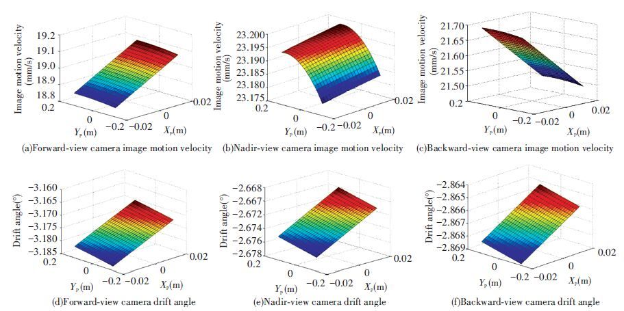
Fig. 3 shows the simulation results of the image motion velocity field of the forward-view, nadir-view and backward-view cameras when imaging on the satellite downlink and at the argument of latitude of 135°. It is shown that the image motion velocity of the nadir-view camera is comparatively large and tends towards stability, whereas the image motion velocities of the forward-view and backward-view cameras along the TDI direction (x axis) differ significantly, and the distribution of drift angle is related to the latitude of ground objects. The main reasons for this disctribution trend include, 1) for the three groups of camera, the sight lengths of each image point on the focal plane vary with imaging attitude; 2) the difference in latitude of ground objects leads to different linear velocities of the earth’s rotation. The simulation results conform to the empirical results of the actual analysis.
|
Figure 3 Distribution of focal plane image motion velocity field |
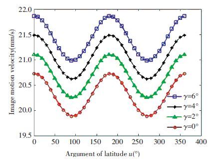
Fig. 4 shows the variation curves of image motion velocity of the focal plane center point along with an argument of latitude u at different off-axis angle γr(0°, 2°, 4° and 6°) of the backward-view camera. With increase in the off-axis angle, the difference between image motion velocity of the off-axis optical system and the coaxial optical system (γr=0°) increases continuously. This phenomenon becomes more obvious in the forward-view camera and the backward-view camera for the earth being a spheroid. Thus, if the same image motion compensation process is directly applied to the off-axis optical system, adopting the computation results of image motion in the coaxial optical system and neglecting the off-axis angle in the modeling process, large error and deterioration in imaging quality will be inevitable.
|
Figure 4 Image motion velocity curves of backward-view camera along with u at different off-axis angles |
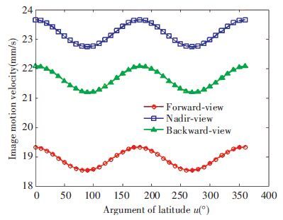
Fig. 5 shows the variation curves of image motion velocity of the focal plane center points of the forward-view, nadir-view and backward-view cameras versus argument of latitude u. It is shown that the variation patterns of the curves are similar. The image motion velocity of the nadir-view camera is the largest since it has the shortest sight length. When u is 0 and 180°, i.e. the cameras are near the equator, the image motion velocity is at the maximum. However, when u is 90° and 270°, i.e. the cameras are near the two poles of the earth, the image motion velocity is at the minimum.
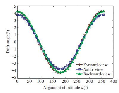
In Fig. 6, as shown by the variation curves of drift angle of the focal plane center point of the forward-view, nadir-view and backward-view cameras versus argument of latitude u, the variation patterns of the three curves are similar. When the cameras are near the equator, the drift angle is at the maximum while when near the two poles, the drift angle is at the minimum. When u falls within interval [0°, 90°] or [180°, 270°], the drift angle of the backward-view camera is larger due to higher linear velocity of the earth’s rotation at ground object points. Similarly, the drift angle of the forward-view camera is greater when u falls within interval [90°, 180°] or [270°, 360°].
|
Figure 5 Image motion velocity curves versus argument of latitude u |
|
Figure 6 Drift angle curves versus argument of latitude u |
3.2 Optimization Schemes for Image Motion Velocity Matching and Drift Angle Matching
For three-line array mapping cameras, the image motion velocity field distributions of the forward-view, nadir-view and backward-view cameras differ as shown in Fig. 3, which sets even higher requirements on image motion compensation technology. Thus, the optimization schemes for image motion velocity matching and drift angle matching play a vital role in improving imaging quality.
Imaging quality of space cameras is usually assessed with MTF[27]. MTFDx and MTFDy in Eq. (22) are modulation transfer functions caused by image motion velocity matching residual and drift angle matching residual under Nyquist space frequency respectively, where N denotes the TDI stages; Δv is the image motion velocity matching residual; Δβ is the drift angle matching residual.
| $\left\{ \begin{align} & MT{{F}_{Dx}}=\frac{sin(\frac{\pi }{2}N\cdot \frac{\Delta v}{v})}{\frac{\pi }{2}N\cdot \frac{\Delta v}{v}} \\ & MT{{F}_{Dy}}=\frac{sin(\frac{\pi }{2}N\cdot tan\text{ }\Delta \beta )\text{ }}{\frac{\pi }{2}N\cdot tan\text{ }\Delta \beta } \\ \end{align} \right.$ | (22) |
In the image motion velocity matching of the three-line array mapping camera, the TDICCD horizontal frequencies of the forward-view, nadir-view and backward-view cameras can be adjusted either independently or uniformly. Though adjusting horizontal frequency independently maximally enhances the focal plane MTF of the cameras, adjusting horizontal frequency uniformly owns the advantage of having the same camera data output rate. This is conducive to the following compression and transmission, and is meanwhile convenient for on-ground image matching. Thus, the horizontal frequency should be adjusted uniformly if feasible under the premise of no influence imaging quality deterioration. According to the simulation results in Fig. 5 and considering that the parameters such as ground resolution, pixel size and intersection angle of the forward-view and backward-view cameras are identical, this paper proposes a scheme for image motion velocity matching optimization under which the nadir-view camera is adjusted independently while the forward-view and backward-view cameras are adjusted uniformly.
In order to guarantee an optimal overall imaging quality, the MTFDx of the forward-view camera and the backward-view camera should be approximately equal when adjusting the horizontal frequency uniformly. Thus, the horizontal frequency controlled variable Flr of the two cameras should satisfy Eq.(23) . However, to ensure an optimal imaging quality of the nadir-view camera, the independent horizontal frequency controlled variable Fv of the nadir-view camera should meet the constraint as shown in Eq. (24) . σk, λk and χk are effective photosensitive areas of the k-th TDICCD of the forward-view camera, the nadir-view camera and the backward-view camera’s focal plane, respectively.
| $\sum\limits_{k=1}^{5}{\iint\limits_{{{\sigma }_{k}}}{MT{{F}_{DX}}^{l}}}ds=\sum\limits_{k=1}^{5}{{}}\iint\limits_{{{\chi }_{k}}}{MT{{F}_{DX}}^{r}}ds$ | (23) |
| $\text{max}\{\sum\limits_{k=1}^{5}{\iint\limits_{{{\lambda }_{k}}}{MT{{F}_{Dx}}^{v}}}ds\}$ | (24) |
In the drift angle matching of the three-line array mapping camera, if the drift angles of the three groups of camera are adjusted independently, then adding the drift mechanism of the focal plane becomes indispensable, which introduces control error of drift mechanism and further reduces mapping accuracy. Thus, the drift angles of three groups of camera should be uniformly adjusted to the greatest possible extent. According to the simulation results in Fig. 6, this paper proposes a scheme for drift angle matching optimization, which enables βlvr, the drift angle adjusted uniformly by the drift mechanism of the focal plane to satisfy Eq.(25) .
| $\text{max}\{\sum\limits_{k=1}^{5}{\iint\limits_{{{\sigma }_{k}}}{MT{{F}_{Dy}}^{l}}}ds+\sum\limits_{k=1}^{5}{\iint\limits_{{{\lambda }_{k}}}{MT{{F}_{Dy}}^{v}}}ds+\sum\limits_{k=1}^{5}{\iint\limits_{{{\chi }_{k}}}{MT{{F}_{Dy}}^{v}}}MT{{F}_{r}}^{r}ds\}$ | (25) |
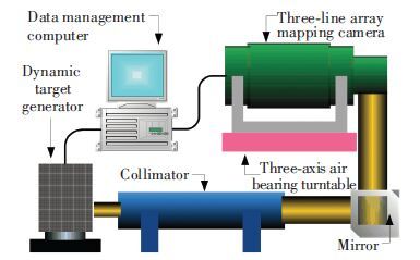
To verify the image motion velocity field model and the proposed matching optimization scheme, a dynamic imaging experiment is carried out with the three-line array mapping camera given in Table 1. The experimental system is shown in Fig. 7, which includes a dynamic target generator, a collimator, a three-axis air bearing turntable, a mapping camera and a data management computer. The dynamic target generator used for simulating the push-broom motion of the camera is equipped with resolution targets, and infinite images are generated by the collimator. The three-axis air bearing turntable is used for simulating a satellite on-orbit micro disturbance environment. The mapping camera is carried by the three-axis air bearing turntable, and the resolution target image is formed behind the collimator through the refraction light path of the mirror. Meanwhile, the data management computer controls the rotational velocity and inclination of the dynamic target generator. Besides, it sends satellite attitude and orbit parameters to the camera controller. The image motion velocity field model and the matching optimization scheme are embedded in the controller DSP which outputs calculation results to carry out image motion compensation.
|
Figure 7 Structure of the dynamic imaging experimental system |
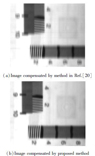
Figs. 8(a) and 8(b) show respectively the resolution target images of the nadir-view camera after image motion compensation using the image motion calculation method proposed in Ref. [20] and the image motion velocity field model in this paper, with 32 TDI stages. By comparison, in Fig. 8(a) apparent image motion exists that gave rise to image quality deterioration, and the line pair image at Nyquist frequency is indistinguishable. However, in Fig. 8(b), the line pair image at Nyquist frequency is clear and distinguishable, which demonstrates the accuracy of the image motion velocity field model.
|
Figure 8 Resolution target images of the nadir-view camera after image motion compensation |
Table 2 tabulates the comparison results of the minimum focal plane MTFDx of the three groups of camera, when the horizontal frequency is adjusted using the mean scheme, the scheme proposed in Ref. [20] or the optimization scheme for image motion velocity matching respectively. When the horizontal frequency is adjusted using the scheme proposed in Ref. [20] or our optimization scheme, the minimum MTFDx of the forward-view camera and the backward-view camera are approximately equal. Compared with the mean scheme, the other two schemes enable the mapping camera to possess better overall performance. However, the scheme proposed in Ref.[20] is specific only to focal plane center points, which obviously weakens the validity of the scheme.
To guarantee imaging quality, it is required that both MTFDx and MTFDy reduction in Eq.(22) should be no higher than 5%. It is known from Table 2 that under the constraint of 5% reduction in MTF, when the horizontal frequency is adjusted uniformly using the mean scheme or the scheme proposed in Ref.[20], the TDI stages will be no more than 3 or 4 respectively. However, when the horizontal frequencies of the forward-view camera and the backward-view camera are adjusted uniformly using the optimization scheme proposed in this paper, the TDI stages reaches a maximum of 6. The three groups of camera should have the horizontal frequency independently adjusted when the TDI stages exceed 6. It is thus evident that the scheme proposed in this paper is more valid.
| Table 2 Minimum focal plane MTFDx of different schemes |
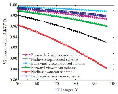
The curves in Fig. 9 shows the variation of the minimum focal plane MTFDy of the three groups of camera along with the TDI stages when the drift angles are uniformly adjusted using the mean scheme and the scheme for drift angle matching optimization. Experiments are carried out when the focal plane drift angle differences of three groups of camera are maximum(u is 180°). Fig. 5 shows that at this time, the drift angle of forward-view camera is slightly larger than that of the backward-view camer, while the nadir-view camera has the minimum drift angle. Thus for the drift angles in Fig. 9 of both methods, the drift angle matching residual of backward-view camera is minimum while that of nadir-view camera is maximum. Furthermore, since the drift angle matching optimization method is proposed based on all points of image focal plane, minimum MTFDy of cameras’ focal planes using drift angel matching optimization scheme are higher than that of the mean scheme with the same TDI stages.
It is shown that under the constraint of 5% reduction in MTF, when the drift angles are uniformly adjusted using the mean scheme, the TDI stages should be controlled and kept below 59. However, when the drift angles are uniformly adjusted using the scheme proposed in this paper, the upper limit of TDI stages can be set to 81. Therefore our scheme is more valid. Since the maximum number of TDI stages of the three-line array mapping camera during on-orbit imaging period is 64, the drift angles can be adjusted uniformly using the proposed scheme. Thus it is needless to add the drift mechanism of the focal plane.
|
Figure 9 Variation curves of the minimum focal plane MTFDy of different schemes |
3.4 Practical Engineering Application
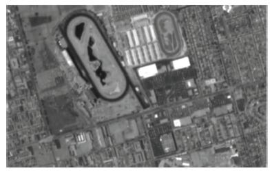
The image motion velocity field model proposed in this paper has been applied in the on-orbit imaging process of an off-axis TMA three-line array aerospace mapping camera. The proposed image motion velocity field model and matching optimization scheme are employed to achieve image motion compensation, the imaging result of nadir-view camera (latitude 35.5°, longitude 76.7°) is shown in Fig. 10. As can be seen, the image gained by nadir-view camera has good quality and owns high information entropy. The on-orbit transfer function calculated by the ground target meets the imaging requirements. This imaging results agree with the previous theoretical analysis, which proves that the proposed image motion velocity field model and matching optimization scheme are accurate and reliable.
|
Figure 10 Imaging result of nadir-view camera |
4 Conclusions
This paper proposes a new method for modeling image motion velocity field of aerospace mapping cameras. An analytic expression of image motion velocity of off-axis TMA three-line array aerospace mapping cameras is deduced from different coordinate systems we established and the attitude dynamics principle. With strong portability, the algorithm can be easily implemented with on-satellite DSPs. The case of a three-line array mapping camera is taken as an example, in which the simulation of the focal plane image motion velocity fields of the forward-view camera, the nadir-view camera and the backward-view camera are carried out and schemes for image motion velocity matching and drift angle matching optimization are formulated according to the simulation results. The experimental results indicate that the accuracy of image motion velocity field model is superior to other existing models and the schemes for image motion velocity matching and drift angle matching optimization are more reasonable than other schemes. The work in this paper effectively enhances the image motion compensation accuracy of off-axis TMA three-line array mapping cameras, providing reliable basis for achieving high-quality mapping images.
| [1] |
Yan Feng, Zheng Ligong, Zhang Xuejun. Image restoration of an off-axis three-mirror anastigmatic optical system with wavefront coding technology.
Optical Engineering, 2008 , 47 (6) : 587-601.
DOI:10.1117/1.2835687 ( 0) 0)
|
| [2] |
Yan Feng, Zheng Ligong, Zhang Xuejun. Design of an off-axis three-mirror anastigmatic optical system with wavefront coding technology.
Optical Engineering, 2008 , 47 (6) : 587-601.
DOI:10.1117/1.2944146 ( 0) 0)
|
| [3] |
Zhang Yongjun, Zheng Maoteng, Xiong Jinxin, et al. On-orbit geometric calibration of ZY-3 three-line array imagery with multistrip data sets.
IEEE Transactions on Geoscience & Remote Sensing, 2014 , 52 (1) : 224-234.
DOI:10.1109/TGRS.2013.2237781 ( 0) 0)
|
| [4] |
Simonetti F, Romoli A, Mazzinghi P, et al. Reflecting telescopes for an orbiting high-resolution camera for Earth observation.
Optical Engineering, 2006 , 45 (5) : 053001.
DOI:10.1117/1.2202920 ( 0) 0)
|
| [5] |
Arefi H, Dangelo P, Mayer H, et al. Iterative approach for efficient digital terrain model production from CARTOSAT-1 stereo images.
Journal of Applied Remote Sensing, 2011 , 5 (2) : 271-278.
DOI:10.1117/1.3595265 ( 0) 0)
|
| [6] |
Crespi M, Barbato F, Vendictis L D, et al. Orientation, orthorectification, terrain and city modeling from Cartosat-1 stereo imagery: preliminary results in the first phase of ISPRS-ISRO C-SAP.
Journal of Applied Remote Sensing, 2008 , 2 (1) : 142-154.
DOI:10.1117/1.2947577 ( 0) 0)
|
| [7] |
Wurm M, Dangelo P, Reinartz P, et al. Investigating the applicability of cartosat-1 DEMs and topographic maps to localize large-area urban mass concentrations.
IEEE Journal of Selected Topics in Applied Earth Observations & Remote Sensing, 2014 , 7 (10) : 4138-4152.
DOI:10.1109/JSTARS.2014.2346655 ( 0) 0)
|
| [8] |
Ni Wenjian, Ranson K J, Zhang Zhiyu, et al. Features of point clouds synthesized from multi-view ALOS/PRISM data and comparisons with LiDAR data in forested areas.
Remote Sensing of Environment, 2014 , 149 : 47-57.
DOI:10.1016/j.rse.2014.04.001 ( 0) 0)
|
| [9] |
Liu Jianhui, Jiang Ting, Jiang Gangwu, et al. Verification and analysis of positioning accuracy of RPC model of TH-1 three-line imagery. ISPDI 2013-Fifth International Symposium on Photoelectronic Detection and Imaging. International Society for Optics and Photonics, 2013, 8908: 165-189. doi:10.1117/12.2042435.
( 0) 0)
|
| [10] |
Zheng Tuanjie, Cheng Jiasheng, Li Heyuan. Instantaneous dynamic change detection based on three-line array stereoscopic images of TH-1 satellite. Remote Sensing of the Environment: 18th National Symposium on Remote Sensing of China. International Society for Optics and Photonics, 2014, 9158: 1187-1190. doi:10.1117/12.2063732.
( 0) 0)
|
| [11] |
Ghosh S K. Image motion compensation through augmented collinearityequations.
Optical Engineering, 1985 , 24 (6) : 1014-1017.
DOI:10.1117/12.7973620 ( 0) 0)
|
| [12] |
Zhi Xiyang, Zhang Wei, Li Liyuan, et al. Restoration of irregularly sampled image degradation due to satellite vibrations.
Journal of Harbin Institute of Technology, 2014 , 46 (9) : 9-14.
( 0) 0)
|
| [13] |
Grycewicz T J, Cota S A, Lomheim T S, et al. Focal plane resolution and overlapped array time delay and integrate imaging.
Journal of Applied Remote Sensing, 2010 , 4 (1) : 043537.
DOI:10.1117/1.3355378 ( 0) 0)
|
| [14] |
Zhao Huijie, Shang Hong, Jia Guorui. Simulation of remote sensing imaging motion blur based on image motion vector field.
Journal of Applied Remote Sensing, 2014 , 8 (1) : 083539.
DOI:10.1117/1.JRS.8.083539 ( 0) 0)
|
| [15] |
Wang Fan, Cao Fengmei, Bai Tingzhu, et al. Experimental measurement of modulation transfer function of a retina-like sensor.
Optical Engineering, 2014 , 53 (11) : 113106.
DOI:10.1117/1.OE.53.11.113106 ( 0) 0)
|
| [16] |
Wang Dejiang, Li Wenming, Yao Yuan, et al. A fine image motion compensation method for the panoramic TDI CCD camera in remote sensing applications.
Optics Communications, 2013 , 298 (7) : 79-82.
DOI:10.1016/j.optcom.2013.02.066 ( 0) 0)
|
| [17] |
Wang Guoliang, Liu Jinguo, Long Kehui, et al. Influence of image motion on image quality of off-axis TMA aerospace mapping camera. Opt. Precision Eng., 2014, 22(3): 806-813.
( 0) 0)
|
| [18] |
Wang Jiaqi, Yu Ping, Yan Changxiang, et al. Space optical remote sensor image motion velocity vector computational modeling, error budget and synthesis.
Chinese Optics Letters, 2005 , 3 (7) : 414-417.
( 0) 0)
|
| [19] |
Wang Chong, You Zheng, Xing Fei, et al. Image motion velocity for wide view remote sensing camera and detectors exposure integration control.
Acta Optic Sinica, 2013 , 33 (5) : 0511002.
DOI:10.3788/AOS ( 0) 0)
|
| [20] |
Wu Xingxing, Liu Jinguo, Kong Dezhu, et al. Image motion compensation of off-axis two-line camera based on earth ellipsoid.
Infrared and Laser Engineering, 2014 , 43 (3) : 838-844.
( 0) 0)
|
| [21] |
Wang Zhenhua, Zhang Miao, Shen Yi. Actuator fault detection and isolation for the attitude control system of satellite.
Journal of Harbin Institute of Technology, 2013 , 45 (2) : 72-76.
( 0) 0)
|
| [22] |
He Donglei, Cao Xiyang. Image motion compensation of three-lines CCD camera stereo mapping satellite by attitude tracking.
Journal of Harbin Institute of Technology, 2006 , 38 (10) : 1744-1747.
( 0) 0)
|
| [23] |
Chen Xiaoli, Feng Yong, Liang Daqiang. Design of operation parameters of a high speed TDI CCD line scan camera.
Journal of Harbin Institute of Technology (New Series), 2006 , 13 (6) : 683-687.
( 0) 0)
|
| [24] |
Wang Dejiang, Zhang Tao, Kuang Haipeng. Clocking smear analysis and reduction for multi phase TDI CCD in remote sensing system.
Optics Express, 2011 , 19 (6) : 4868-4880.
DOI:10.1364/OE.19.004868 ( 0) 0)
|
| [25] |
Hu Jun, Cao Xiaotao, Wang Dong, et al. Dynamic closed-loop test for real-time drift angle adjustment of space camera on the Earth. Proceedings of the 5th International Symposium on Advanced Optical Manufacturing and Testing Technologies. International Society for Optics and Photonics, 2010.76560Z.
( 0) 0)
|
| [26] |
Liu Hailong, Han Chengshan, Li Xiangzhi, et al. Vibration parameter measurement of TDICCD space camera with mechanical assembly.
Optics and Precision Engineering, 2015 , 23 (3) : 729-737.
DOI:10.3788/OPE.20152303.0729 ( 0) 0)
|
| [27] |
Lv Hengyi, Xue Xucheng, Zhao Yunlong, et al. Measurement and experiment of modulation transfer fuction at Nyquist frequency for space optical cameras.
Optics and Precision Engineering, 2015 , 23 (5) : 1484-1489.
DOI:10.3788/OPE. ( 0) 0)
|
 2016, Vol. 23


