2. School of Electrical Engineering, Hebei University of Science and Technology, Shijiazhuang 050018, China
With the development of wind power system towards to high power, permanent magnet synchronous motor (PMSM) based on direct-drive wind power system is receiving more and more attention[1-3]. Compared to the vector control of PMSM, direct torque control has faster torque response speed, which makes it more suitable for wind power system[4-5].
The observation of stator flux and electromagnetic torque is the basis of direct torque control[6-9]. The commonly used stator flux observation method mainly includes the voltage model based stator flux observer and the current model based stator flux observer.
The traditional voltage model based stator flux observer is less sensitive to motor parameters. However, the pure integral operation contained in this stator flux observer is affected by the integral initial values, integral drift and the DC offset. Meanwhile, although the conventional current model based stator flux observer is robust to the pure integral operation, it is sensitive to motor parameters. As the generator often operates in the high speed region of wind power system, the voltage model based stator flux observer is more appropriate. In Refs. [10-15], different improved voltage models based stator flux observers were proposed and researched. In Ref. [10], a low-pass filter was adopted instead of the pure integral operation to eliminate the effect of integral initial values and integral drift on stator flux observation precision, but the DC offset inhibition ability is limited. In Ref. [11], a cascading low-pass filter is adopted to achieve the stator flux observation and the observer’s dynamic response is improved through the regulation of the order of the low-pass filter and phase-amplitude compensation module. However, its DC offset inhibition ability is still limited. Different to Refs. [10-15], a high-pass filter is used to replace the pure integral operation and an improved stator flux observation method is achieved in Ref. [12]. In this observer, the DC offset is eliminated. However, the low-order harmonics, such as 3th, 5th, 7th and so on, contained in the stator voltage and current will affect the stator flux observation precision. Band-pass filter was used to take the place of the pure integral operation in order to improve stator flux observation precision in Refs. [13-14]. However, the design procedure is too complicated. In Ref. [15], a new stator flux observer was designed based on the fact that the electromotive force is orthogonal to the stator flux, but another two proportion integral coefficients are needed. A neural network based stator flux observer was proposed in Ref. [16]. But this method cannot be used in engineering practice. In Ref. [17], a stator flux observation algorithm based on the sliding mode observer is proposed. Although the sliding mode observer is robust to the external disturbance, its DC offset inhibition ability is limited as the methods proposed in Refs. [10-11]. In Refs. [18-20], a voltage and current model based stator flux observer is researched. But the effects of the motor inductance parameters remain to be further studied.
In recent years, Zhao et al. designed a new stator flux observer in Ref. [21] based on the second-order generalized integrator (SOGI), which is widely applied to the grid inverter control system. However, the method is sensitive to DC offset too.
In this paper, the method proposed in Ref. [21] and influenced by DC offset is analyzed and revealed, then, in order to eliminate the effect of DC offset in the observer proposed in Ref. [21], an improved SOGI based stator flux observer is presented and then, system simulation and experimental results of stator flux and torque observation based on the SOGI and the improved SOGI are shown and compared, at last, the conclusion is given.
2 The Stator Flux Observation Method of PMSM Based on SOGIThe pure integral operation contained in this stator flux observer based on voltage model is affected by the integral initial values and integral drift, therefore, an improved voltage model based stator flux observer is proposed in Ref. [21] based on SOGI. However, this method is sensitive to DC offset and it will be analyzed as follows.

|
Figure 1 shows the typical block diagram of SOGI. |
Fig. 1 Block diagram of SOGI
The transfer function of SOGI meets:
| $\frac{{{u}_{0}}\left( s \right)}{u\left( s \right)}=\frac{k{{\omega }_{e}}s}{{{s}^{2}}+k{{\omega }_{e}}s+{{\omega }_{e}}^{2}}$ | (1) |
| $\frac{q\left( s \right)}{u\left( s \right)}=\frac{k{{\omega }_{e}}^{2}}{{{s}^{2}}+k{{\omega }_{e}}s+{{\omega }_{e}}^{2}}$ | (2) |
When s=jωe, Eqs.(1) and (2) can be simplified as:
| $\left\{ \begin{array}{*{35}{l}} \frac{{{u}_{0}}\left( s \right)}{u\left( s \right)}=1 \\ \frac{q\left( s \right)}{u\left( s \right)}=\frac{1}{j} \\ \end{array} \right.$ | (3) |
It can be seen from Eq.(3) that when the frequency of input signal u(s) of SOGI is ωe, the output signal u0(s) is the same with u(s) and the output signal q(s) is orthogonal to the input signal u(s). Due to this feature, SOGI is widely used in the control system of single phase grid-connected inverters.
Meanwhile, the transfer function of ψ0 and u can be expressed as:
| $\frac{{{\psi }_{0}}\left( s \right)}{u\left( s \right)}=\frac{k{{\omega }_{e}}}{{{s}^{2}}+k{{\omega }_{e}}s+{{\omega }_{e}}^{2}}$ | (4) |
When s=jωe, Eq.(4) can be obtained as:
| $\frac{{{\psi }_{0}}\left( s \right)}{u\left( s \right)}=\frac{1}{j{{\omega }_{e}}}$ | (5) |
It is apparent that the signal ψ0(s) is the integration of input signal u(s) and it is independent of the integral initial values and integral drift. So the SOGI can be used to observe the stator flux of PMSM. If the input signal u(s) is the stator back electromotive force of PMSM, the output signal ψ0(s) is the observed stator flux. This is the stator flux observer proposed in Ref. [21] by Zhao. However, this method is sensitive to DC offset and it will be analyzed in the following sections.
Fig. 2 shows the bode diagram of the transfer function given in Eq.(4) when the synchronous frequency ωe is 31.4 rad/s. As can be seen from Fig. 2, when k is increased, the gain of DC offset is magnified, which means that the DC offset inhibiting ability of Eq.(4) is weakened when k is increased. However, even when k is increased to 10, the gain of DC offset is still less than zero, which means that the algorithm shown in Eq.(4) still has the ability to restrain DC deviator.
Similarly to Fig. 2, Fig. 3 is given when ωe=3.14 rad/s. From Fig. 3, it can be seen obviously that when k is increased to 10, the gain of DC offset is large than zero, i.e. the influence of DC offset is magnified. So it is concluded that the strategy proposed in Ref.[21] is easily influenced by DC offset. So an improved stator flux observation technique based on SOGI is proposed in this paper and it will be described in the next part.

|
Figure 2 Bode diagram of Eq.(4) with ωe=31.4 rad/s |

|
Figure 3 Bode diagram of Eq.(4) with ωe=3.14 rad/s |
3 Improved Stator Flux Observation Method Based on SOGI
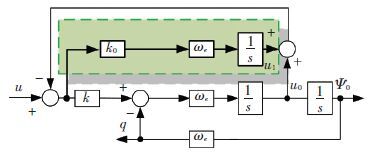
In the actual motor control system, the sampled voltage and current always contains DC bias. In this situation, when the stator flux observation method proposed in Ref.[21] is adopted, the obtained stator flux will contain DC offset, therefore, an improved stator flux observation method is proposed based on an improved SOGI as shown in Fig. 4.
|
Figure 4 Block diagram of the improved SOGI |
Compared to Fig. 1, the improved SOGI adds a branch. This added branch can estimate the DC offset contained in the input signal and the estimated DC offset is subtracted from the input signal. As a result, the output signal is insensitive to DC offset. Thus, the stator flux can be observed accurately based on this improved SOGI. The detailed analysis will be given in the following sections.
The transfer function of the improved SOGI meets:
| $\frac{{{u}_{0}}\left( s \right)}{u\left( s \right)}=\frac{{{k}_{0}}{{\omega }_{e}}({{s}^{2}}+{{\omega }_{e}}^{2})}{{{s}^{3}}+({{k}_{0}}+k){{\omega }_{e}}{{s}^{2}}+{{\omega }_{e}}^{2}s+{{k}_{0}}{{\omega }_{e}}^{3}}$ | (6) |
| $\frac{{{\psi }_{0}}\left( s \right)}{u\left( s \right)}=\frac{k{{\omega }_{e}}s}{{{s}^{3}}+({{k}_{0}}+k){{\omega }_{e}}{{s}^{2}}+{{\omega }_{e}}^{2}s+{{k}_{0}}{{\omega }_{e}}^{3}}$ | (7) |
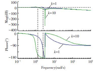
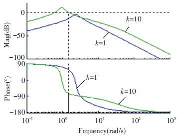
Choosing ωe=3.14 rad/s and k0=1, the bode diagram of the transfer functions given in Eqs.(6) and (7) are shown in Figs. 5 and 6.
From Fig. 5, it is seen that whatever k is, the transfer function of Eq.(6) is an all-pass filter for the DC signal. Besides, it is a band stop filter for the signal whose frequency is ωe. Because of this property, the DC offset contained in the input signal can be observed by Eq.(6) . Meanwhile, although the gain of DC offset of Eq.(7) as shown in Fig. 6 is enlarged when k is increased, it is still less than zero, which means that the DC offset can be still restrained compared to Fig. 3. Substitute s=0 into Eq.(7) , the result of Eq.(7) is zero, which means that in theory the DC offset can be eliminated by Eq.(7) completely. What’s more, substitute s=jωe into Eq.(7) , Eq.(8) is obtained as:
| $\frac{{{\psi }_{0}}\left( s \right)}{u\left( s \right)}=\frac{1}{j{{\omega }_{e}}}$ | (8) |
|
Figure 5 Bode diagram of Eq.(6) with ωe=3.14 rad/s |
|
Figure 6 Bode diagram of Eq.(7) with ωe=3.14 rad/s |
From Eq.(8) , it is known that the improved SOGI can be used to observe the stator flux.
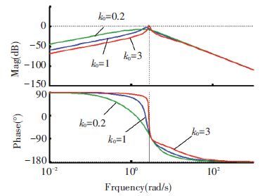
Besides, the design of k0 is researched. Choosing ωe=3.14 rad/s and k=1, the bode diagram of the transfer function given in Eq.(7) is shown in Fig. 7 with different k0.
|
Figure 7 Bode diagram of Eq.(7) with different k0 |
It is seen from Fig. 7 that if k0 is reduced, the low-frequency gain of Eq.(7) is increased. Meanwhile, if k0 is too large, the resonance peak of Eq.(7) is increased. As a result, in order to decrease the low-frequency gain with the resonance peak of Eq.(7) , a compromise value of k0 must be chosen. In this paper, according to Fig. 7, k0 is suggested to be chosen between 0.2 and 3.
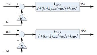
Finally, the proposed stator flux observer based on improved SOGI is obtained as shown in Fig. 8. In Fig. 8, usα and usβ are the stator voltage of PMSM in the stationary α-β reference frame, and isα and isβ are the stator current of PMSM in the stationary α-β reference frame, and Rs is stator resistance, and ψsα and ψsβ are the observed stator flux.
Based on Fig. 8, the electromagnetic torque can be observed based on Eq.(9) .
| ${{T}_{e}}={{p}_{n}}({{\psi }_{s\alpha }}{{i}_{s\beta }}-{{\psi }_{s\beta }}{{i}_{s\alpha }})$ | (9) |
where Te is the observed electromagnetic torque and pn is the pole pairs of PMSM.
|
Figure 8 The proposed stator flux observation method of PMSM based on the improved SOGI |
4 Simulation Results
The rated parameters of PMSM used in the simulation and experiment are listed as Un=380 V, fn=50 Hz, Tn=70 Nm, np=2, Rs=0.6 Ω, Ld=24 mH, Lq=24 mH, and f=1.2 Wb.
In the simulation, the PMSM is operating at 600 r/min with id=0, iq =10 A. A DC offset of -10 V is added to usα at 0.4 s, meanwhile, another DC offset of 10 V is added to usβ at 0.4 s, then, the speed steps down to 300 r/min at 0.8 s. It should be pointed out that the simulation model is established based on Matlab/Simulink. The DC offsets are added to usα and usβ respectively based on two step signal sources in Matlab/Simulink.
In the first simulation, the method proposed in Ref. [21] is tested and the simulation results are given in Fig. 9. As shown in Fig. 9(a), the actual electromagnetic torque is about 35 Nm in the whole simulation procedure. When DC offset is added to the stator voltage at 0.4 s, a DC drift is appeared in the observed stator flux

|
Figure 9 Simulation results based on the method in Ref.[21] |
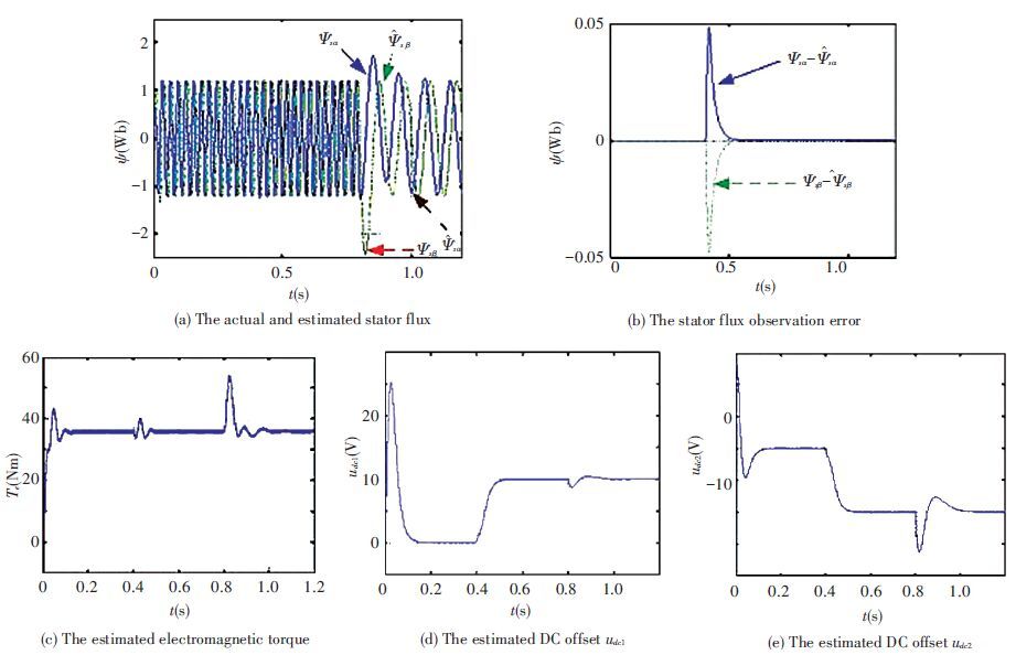
In the second simulation, the method proposed in this paper is tested and the simulation results are given in Fig. 10. As can be seen from Figs. 10(a) and 10(b), although the stator flux observation errors are enlarged immediately when the DC offsets are added suddenly at 0.4 s, the errors decrease to zero fast within less than 0.1 s. As a result, the observed stator flux and electromagnetic torque is not affected by the added DC offset, which means that the stator flux and torque observation precision is improved. Besides, the added DC offset can be estimated too, as shown in Figs. 10(d) and 10(e). Meanwhile, it should be pointed out that the electro-magnetic torque observation error is large at 0.8 s. This is due to the sudden step of the speed in the simulation. In the practical PMSM control system, the speed step rarely happens due to the large inertia of PMSM. Thus the electromagnetic torque observation error is limited.
In the third simulation, the harmonic suppression characteristic of the proposed method is tested and compared to the conventional method proposed in Ref.[21]. In this simulation, the PMSM is operating at 300 r/min with id=0, iq =10 A. A harmonic current as shown in Eq.(10) is injected into the sampled current in order to test the harmonic suppression characteristic. The simulation result of the proposed method is shown in Fig. 11(a), and the simulation result of the conventional method is shown in Fig. 11(b).
|
Figure 10 Simulation results based on the proposed method |

|
Figure 11 Simulation results of the proposed method and the conventional method when harmonic current is injected |
| ${{i}_{3}}=3\text{sin}(60\pi t)$ | (10) |
It is apparent to see from Fig. 11 that when aharmonic current as shown in Eq.(10) is injected into the sampled current, a 3th harmonic is appeared in the stator flux observation error. Both the proposed method and the conventional method have similar stator flux observation error, which means that both of the two methods have similar harmonic suppression ability.
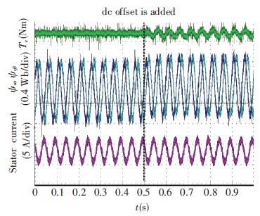
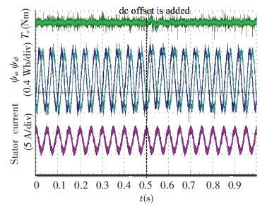
5 Experimental ResultsIn the experiment, an induction motor controlled by another converter is used as a prime mover to drive the tested PMSM. The control system is developed based on DSP 28335. The sample frequency is 4 kHz and the switching frequency is 2 kHz. The proposed stator flux and electromagnetic torque observation method is achieved in the discrete control system. In the first situation, the speed is controlled as 600 r/min. Two DC offsets of 10 V are added to the stator voltage usα and usβ respectively at the time marked in Fig. 12. It should be pointed out that in the DC offsets are added to the sampled stator voltage in the DSP, rather than added to actual stator voltage. As can be seen from Fig. 12, the observed stator flux and electromagnetic torque are heavily affected by the intentional added DC offset based on the method in Ref.[21]. As a comparison, Fig. 13 is given based on the proposed method. As can be seen from Fig. 13, the influence of DC offset is completely eliminated.
|
Figure 12 Experimental results of stator flux and electromagnetic torque based on the method in Ref.[21] at 600 r/min |
|
Figure 13 Experimental results of stator flux and electromagnetic torque based on the proposed method at 600 r/min |
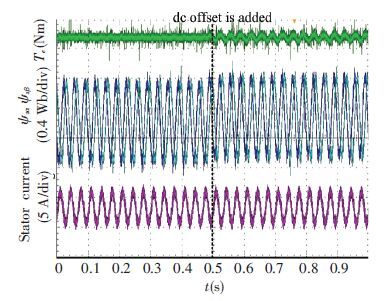
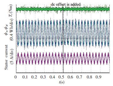
In the second situation, the speed is controlled as 900 r/min. The same DC offset is added at the time marked in Fig. 14. Fig. 14 is given based on the method designed in Ref.[21] and the result based on the proposed method is given in Fig. 15.
Compared Fig. 14 with Fig. 12, it can be seen when the speed is accelerated, the influence of DC offset is decreased. In other words, the lower the speed is, the stronger the influence of DC offset is. In addition, it is apparent that the influence of DC offset is completely eliminated based on the method proposed in this paper as can be seen from Fig. 15.
|
Figure 14 Experimental results of stator flux and electromagnetic torque based on the method designed in Ref.[21] at 900 r/min |
|
Figure 15 Experimental results of stator flux and electromagnetic torque based on the proposed method at 900 r/min |
6 Conclusions
This paper proposes an improved stator flux and electromagnetic torque observation method of PMSM based on an improved SOGI. Compared with the SOGI method, the simulation and experimental results verity that the improved method is robust to the DC offset contained in the stator voltage or current of PMSM and the stator flux and electromagnetic torque observation accuracy is improved effectively.
| [1] |
Yaramasu V, Wu Bin. Predictive control of three-level boost converter and NPC inverter for high power PMSG-based medium voltage wind energy conversion systems.
IEEE Transactions on Power Electronics, 2014 , 29 (10) : 5308-5322.
DOI:10.1109/TPEL.2013.2292068 ( 0) 0)
|
| [2] |
YaramasuV, Wu Bin, Chen Jin. Model-predictive control of grid-tied four-level diode-clamped inverters for high-power wind energy conversion systems.
IEEE Transactions on Power Electronics, 2014 , 29 (6) : 2861-2873.
DOI:10.1109/TPEL.2013.2276120 ( 0) 0)
|
| [3] |
MendisN, Muttaqi K M, Perera S. Management of battery-supercapacitor hybrid energy storage and synchronous condenser for isolated operation of PMSG based variable-speed wind turbine generating systems.
IEEE Transactions on Smart Grid, 2014 , 5 (2) : 944-953.
DOI:10.1109/TSG.2013.2287874 ( 0) 0)
|
| [4] |
Foo G H B, Rahman M F. Direct torque control of an IPM-synchronous motor drive at very low speed using a sliding-mode stator flux observer.
IEEE Transactions Power Electronics, 2010 , 25 (4) : 933-942.
DOI:10.1109/TPEL.2009.2036354 ( 0) 0)
|
| [5] |
Zhang Zhe, Zhao Yue, Qiao Wei, et al. A space-vector modulated sensorless direct-torque control for direct-drive PMSG wind turbines.
IEEE Transactions Industry Applications, 2014 , 50 (4) : 2331-2341.
DOI:10.1109/IAS.2012.6374041 ( 0) 0)
|
| [6] |
GuoLeilei, Zhang Xing, Yang Shuying, et al. Super-twisting sliding mode observer based speed sensorless torque control for PMSG used in wind turbines. Proceedings of 2015 9th International Conference on Power Electronics and ECCE Asia (ICPE-ECCE Asia). Seoul. 2015. 2457-2462.
( 0) 0)
|
| [7] |
Zhang Xinghua, Nie Jing, Wang Deming. Variable-structure anti-windup controller for direct torque controlled induction motor drives.
Electric Machines and Control, 2013 , 17 (1) : 77-81.
( 0) 0)
|
| [8] |
Chen Zhen, Liu Xiangdong, Dai Yaping, et al. Novel direct torque control of PMSM based on expected voltage space vector modulation.
Electric Machines and Control, 2009 , 13 (1) : 40-46.
( 0) 0)
|
| [9] |
Lin Bin, Sun Dan, He Yikang. High-speed operation range extension for direct torque controlled permanent magnet synchronous motors.
Electric Machines and Control, 2014 , 18 (9) : 9-16.
( 0) 0)
|
| [10] |
Comanescu Mihai, Xu Longya. An improved flux observer based on PLL frequency estimator for sensorless vector control of induction motors.
IEEE Transactions on Industrial Electronics, 2006 , 53 (1) : 50-56.
DOI:10.1109/TIE.2005.862317 ( 0) 0)
|
| [11] |
He Zhiming, Liao Yong, Xiang Dawei. A new flux estimation method based on modified programmable cascaded low-pass filter.
Transactions of China Electrotechnical Society, 2008 , 23 (4) : 54-58.
( 0) 0)
|
| [12] |
Wang Yu, Deng Zhiquan, Wang Xiaolin. A novel algorithm of motor flux estimation.
Proceedings of the CSEE, 2007 , 27 (6) : 39-44.
( 0) 0)
|
| [13] |
Chang Qiankun, Ge Qiongxuan, Zhang Bo. Research on the band-pass-filter compensation voltage model of induction motors.
Proceedings of the CSEE, 2014 , 34 (9) : 1404-1414.
( 0) 0)
|
| [14] |
Zhang Xing, Qu Wenlong, Lu Haifeng. A New Integrator for Voltage Model Flux Estimation in a Digital DTC System.
TENCON, Hong Kong, 2006 : 1-4.
( 0) 0)
|
| [15] |
Zhang Jie, Chai Jianyun, Sun Xudong, et al. An improved voltage model integral algorithm of induction motors based on the orthogonality between back EMF and flux.
Transactions of China Electrotechnical Society, 2014 , 29 (3) : 42-49.
( 0) 0)
|
| [16] |
Liu Guorong, Zhang Daolu. A study of motor flux neural network observer.
Electric Machines and Control, 2011 , 15 (8) : 81-87.
( 0) 0)
|
| [17] |
Guo Leilei, Zhang Xing, Yang Shuying, et al. Speed Sensorless Torque Closed-Loop Vector Control of IPMSM. Proceedings of 2014 International Electronics and Application Conference and Exposition (PEAC). Shanghai. 548-552.
( 0) 0)
|
| [18] |
Lascu C, Boldea I, Blaabjerg F. Direct torque control of sensorless induction motor drives: A sliding-mode approach.
IEEE Transactions on Industry Applications, 2004 , 40 (2) : 582-590.
DOI:10.1109/TIA.2004.824441 ( 0) 0)
|
| [19] |
Lascu C, Andreescu G-D. Sliding-mode observer and improved integrator with DC-offset compensation for flux estimation in sensorless-controlled induction motors.
IEEE Transactions on Industry Electronics, 2006 , 53 (3) : 785-794.
DOI:10.1109/TIE.2006.874275 ( 0) 0)
|
| [20] |
Paicu M C, Boldea I, Andreescu G-D. Very low speed performance of active flux based sensorless control: interior permanent magnet synchronous motor vector control versus direct torque and flux control.
IET Electric Power Applications, 2009 , 3 (6) : 551-561.
DOI:10.1049/iet-epa.2008.0290 ( 0) 0)
|
| [21] |
Zhao Xin, Jin Xinmin, Li Geliang, et al. New flux observer of direct-drive electrically excited synchronous generators.
Transactions of China Electrotechnical Society, 2013 , 28 (10) : 75-82.
( 0) 0)
|
 2016, Vol. 23


