In the offshore oil and gas and submarine telecommunication industries, pipelines and cables are laid on the seabed to transmit energy or information data across the ocean. They are buried under the seabed in order to avoid damages from fishing activities, dropped objects, vessel anchors, current and wave pounding and so on[1-3]. Subsea trenchers equipped with trenching systems are used to bury pipelines and cables, which have drawn lots of attention in submarine pipeline and cable engineering in recent decades[4-5]. Mechanical trenchers are classified into three types according to different trenching modes, including jetting, ploughing and cutting[6]. The type of trenchers for engineering should be chosen according to soil properties, sea conditions, pipeline installations and backfill methods, and the dimensions and materials of the pipelines and cables[7].
The jet trencher is considered robust and effective in pipeline engineering because it is fairly simple and only has a small number of moving parts[3]. During the burying process, the pipelines or cables are first laid on the seabed. Then the jet trencher moves along the pipeline with a high-speed water jet to create a slot there in the soil, which allows the pipeline or cables to descend into the seabed. The suspended soil is sucked up and side-casted at the same time.
The jet trencher is a kind of underwater tethered system, which is attached to a tether (or cable) and suspended from a surface vessel.It has much more submerged weight and negative buoyancy which is quite different from conventional ROV (Remotely Operated Vehicle) with nearly neutral buoyancy. When the trencher is lowered down into the water, there are various external forces acting on the trencher. When there exit ocean currents, the trencher will oscillate due to external excitations and offset from the pipeline route, which influence the safety, stability and working efficiency of the trencher system. From the point of view of control engineering, the thrust system is constructed to recover and reposition the shift trencher to the center of the pipeline route, in order to ensure the trench precision and quality and reduce working time[8].
Vertical oscillation behavior subject to surface excitation has already been widely studied[9-10], but less attention is paid to the lateral oscillation behavior, which is also quite important in underwater locating, time and position control of hanging work and controlling the operating range of suspension systems. There are two kinds of modeling techniques available to predict the response of tethered systems: the continuous analytical methods and the discrete numerical models[11]. Numerical models are effective for some nonlinear properties like quadratic drag, and the nonlinear coupling motion principle between the tether and vehicle can also be included. Numerical methods are valid tools but they also have several limitations. They need much calculation time and cannot provide quick estimates of dynamic characteristics of tethered systems[12-13]. However, the analytical methods are not constrained by these limitations[14]. They can accurately and concisely summarize the relationship between variables, and values of independent variables can be easily obtained through inverse calculation corresponding to the dependent variables. But the analytical methods can only be used for some specific motion cases with fewer degrees of freedom. Lueck[15] derived a linear frequency-domain analytic model of vertically tethered systems with inverse fourier transform techniques, and obtained the response wavelets of the tether tension and motion.
Main purpose of this paper is to establish a nonlinear one-dimension alanalytic model that accurately represents the lateral oscillation behavior of a trencher in ocean currents, and find the approximate analytical solution, which will be useful to predict the oscillation characteristics.
PID controllers are widely used in engineering despite continued advancement in control technology. A lot of the industrial loops are controlled by PID regulators due to their simple structure, near optimal performance and robustness, applicability over wide range, ease in implementation, etc[16]. For the thrust system of the jet trencher, a double-loop PID controller is designed to control the lateral motion displacement of the trencher to make it return to the position right above the pipelines.
2 Mathematical ModelIn ocean current environment, the jet trencher may oscillate and offset due to external excitations with the surface ship floating and the tether length varying. Its motion characteristics have great complexity. For simplicity, the tethered trencher is viewed as a pendulum to get the vibration equation, and some assumptions are made as follows:
1) The tethered trencher oscillates in small amplitude;
2) Without considering the tether's elastic extension, effects of gravity and flow resistance of the tether are neglected, because they are too much smaller compared to the forces directly acted on the suspended trencher;
3) Regardless of motion of the mother ship, the transport inertial force and Coriolis inertial force are zero, namely FIe=0 and FIC=0. The change of position where the tether is connected to the surface ship is ignored.
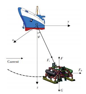
Fig. 1 shows the jet trencher connected to the mother ship by a long tether. The system is simplified into a single degree of freedom model with restoring force and damping forces. In order to analyze the motion of the trencher, the coordinate frame yoz is first established as shown in Fig. 1, and the origin o is set in the center of the bottom of ship. The coordinate axis y directs to lateral side horizontally, and coordinate axis z is vertical and directed from top to bottom. The lateral displacement between the trencher and coordinate axis z is defined as y.
|
Figure 1 Definition of coordinate system and symbols |
The trencher is acted upon by the following forces:
1) Gravity G=mg, buoyancy F=ρVg=mfg;
2) Added mass force due to acceleration
3) Tether tension Ft;
4) Considering the influence of ocean current, the drag force on the trencher can be divided into two parts: linear hydrodynamic drag FDL and nonlinear hydrodynamic drag FDNL as follows:
| $ {F_D} = {F_{DL}} + {F_{DNL}} = {Y_v}\left( {\dot y - {v_c}} \right) + {Y_{\left| v \right.\left| v \right.}}\left| {\dot y - {v_c}} \right|\left( {\dot y - {v_c}} \right) $ |
where Yv and Y|v|v are the first and second order hydrodynamic coefficients along the y-axis due to a velocity in the y-direction; y is the lateral displacement and vc is ocean current velocity[17].
Due to D'Alembert principle, the basic equation of relative motion dynamics is established, and projected to the tangent axis
| $ \begin{array}{l} m\ddot s = - \left( {G - F} \right)\sin \varphi + {Y_{\dot v}}\ddot s + \left[ {{Y_v}\left( {\dot s - {v_c}\cos \varphi } \right) + } \right.\\ \;\;\;\;\;\;\;\;\left. {{Y_{\left| v \right.\left| v \right.}}\left| {\dot s - {v_c}\cos \varphi } \right|\left( {\dot s - {v_c}\cos \varphi } \right)} \right] \end{array} $ | (1) |
where s is the displacement on the oscillation trajectory; -(G-F) sin φ represents the tangent component of gravity and buoyancy. As the trencher makes micro-amplitude vibration, deflection angle φ is small, consider s≈y, s≈φl, sin φ≈φ, cos φ≈1, then Eq.(1) can be written as:
| $ \begin{array}{l} \left( {m - {Y_{\dot v}}} \right)\ddot y = - \left( {G - F} \right)\frac{y}{l} + {Y_v}\left( {\dot y - {v_c}} \right) + \\ \;\;\;\;\;\;\;\;\;\;\;\;\;\;\;\;\;{Y_{\left| v \right.\left| v \right.}}\left| {\dot y - {v_c}} \right|\left( {\dot y - {v_c}} \right) \end{array} $ | (2) |
Eq.(2) is the differential equation describing the oscillation behavior of a trencher in ocean current environment. The equation has the term of ocean currents, which is the key point different from conventional simple pendulum equations. Due to the effect of the damping term, the amplitude decays constantly.
3 Approximate Analytical SolutionIn the above section, the differential equation governing the oscillation of the trencher in ocean currents with a single degree of freedom is obtained. As the vibration equation has the term of absolute value, it is difficult to solve the nonlinear differential equation. In order to get the analytical solution and guarantee the same steady offset displacement, the nonlinear term of absolute value is simplified and the linear oscillation model is obtained asfollows:
| $ \begin{array}{l} \left( {m - {Y_{\dot v}}} \right)\ddot y = - \left( {G - F} \right)\frac{y}{l} + {Y_v}\left( {\dot y - {v_c}} \right) - \\ \;\;\;\;\;\;{Y_{\left| v \right.\left| v \right.}}v_c^2 \end{array} $ | (3) |
Eq.(3) can be rewritten in the following form:
| $ \ddot y - \frac{{{Y_v}}}{{\left( {m - {Y_{\dot v}}} \right)}}\dot y + \frac{{\left( {G - F} \right)}}{{\left( {m - {Y_{\dot v}}} \right)l}}y = - \frac{{{Y_v}{v_c} + {Y_{\left| v \right.\left| v \right.}}v_c^2}}{{\left( {m - {Y_{\dot v}}} \right)}} $ | (4) |
Solving the above equation, we obtain:
| $ \begin{array}{l} y = - \frac{{l\left( {{Y_v}{v_c} + {Y_{\left| v \right.\left| v \right.}}v_c^2} \right)}}{{\left( {G - F} \right)}} + \\ \;\;\;\;\;{C_1}e\frac{{\left( {l{Y_v} - \sqrt { - 4\left( {G - F} \right)lm + {l^2}{Y_v}^2 + 4\left( {G - F} \right)l{Y_{\dot v}}} } \right)}}{{2\left( {m - {Y_{\dot v}}} \right)l}}t + \\ \;\;\;\;\;{C_2}e\frac{{\left( {l{Y_v} - \sqrt { - 4\left( {G - F} \right)lm + {l^2}{Y_v}^2 + 4\left( {G - F} \right)l{Y_{\dot v}}} } \right)}}{{2\left( {m - {Y_{\dot v}}} \right)l}}t \end{array} $ | (5) |
where C1 and C2 are undetermined parameters.
Giving initial conditions y(0)=y0 and ẏ(0)=0, and substituting them into Eq.(5), C1, C2 can be obtained as:
| $ \left\{ \begin{array}{l} {C_1} = \frac{{\left[ {\left( {G - F} \right){y_0} + l{Y_v}{v_c} + l{Y_{\left| v \right.\left| v \right.}}v_c^2} \right]\left( {l{Y_v} + \sqrt { - 4\left( {G - F} \right)lm + {l^2}{Y_v}^2 + 4\left( {G - F} \right)l{Y_{\dot v}}} } \right)}}{{2\left( {G - F} \right)\sqrt { - 4\left( {G - F} \right)lm + {l^2}{Y_v}^2 + 4\left( {G - F} \right)l{Y_{\dot v}}} }}\\ {C_2} = \frac{{\left( {G - F} \right){y_0} + l{Y_v}{v_c} + l{Y_{\left| v \right.\left| v \right.}}v_c^2}}{{\left( {G - F} \right)}} - \frac{{\left[ {\left( {G - F} \right){y_0} + l{Y_v}{v_c} + l{Y_{\left| v \right.\left| v \right.}}v_c^2} \right]\left( {l{Y_v} + \sqrt { - 4\left( {G - F} \right)lm + {l^2}{Y_v}^2 + 4\left( {G - F} \right)l{Y_{\dot v}}} } \right)}}{{2\left( {G - F} \right)\sqrt { - 4\left( {G - F} \right)lm + {l^2}{Y_v}^2 + 4\left( {G - F} \right)l{Y_{\dot v}}} }} \end{array} \right. $ | (6) |
Eq.(5) is the approximate analytical solution, and C1, C2 adopt the parameters in Eq.(6). According to Eq.(5), the amplitude in ocean currents decays with time.
As moving in ocean currents, the trencher will not oscillate around the z axis and will have a lateral offset displacement, which can be got from static equilibrium. If letting
Different parameters are given to the analytical expressions to analyze the effects of the different types of damping, and validate the analytical solution for cases in ocean currents. For the trencher, the initial conditions give y(0)=5 and ẏ(0)=0, and parameters for the dynamic analysis are listed in Table 1.
| Table 1 Parameters for the dynamic analysis |
For the drag force, Yv and Yvv are the first and second order hydrodynamic coefficients and can be obtained from the dimensionless coefficients. However, the dimensionless hydrodynamic coefficients are usually obtained with model experiment or CFD simulation, which are not key research emphasis in this paper. In order to perform dynamic analysis and control of lateral oscillation, the dimensionless hydrodynamic coefficients from heavy duty ROV are used for this trencher due to their similar frame structure as follows:
| $ \begin{array}{l} {{Y'}_v} = {Y_v}/0.5\rho {u_c}LH = - 0.781\\ {{Y'}_{\dot v}} = {Y_{\dot v}}/0.5\rho {L^2}H = - 0.099\\ {{Y'}_{\left| v \right.\left| v \right.}} = {Y_{\left| v \right.\left| v \right.}}/0.5\rho LH = - 0.065 \end{array} $ |
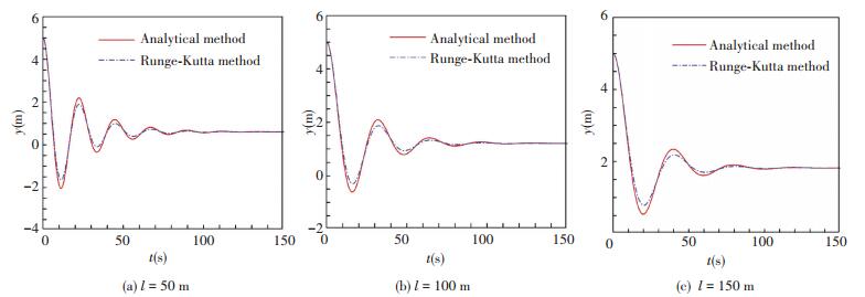
The relationships between lateral displacement and time with different tether length are plotted in Fig. 2, and the results obtained from analytical solution are compared with numerical results. As shown in the graph, the calculated values of lateral displacement with analytical method have a similar trend to those of numerical results, but the amplitudes of numerical results are smaller than analytical ones. The maximum difference between lateral displacements obtained with analytical method and numerical method is less than 0.5 m, so it is conservative and safe to estimate the oscillation behavior with the analytical solution.
With the increase of time, lateral displacement first oscillates, and then gradually damps into a steady status. The steady lateral displacements with both analytical and Runge-Kutta method are almost the same. The oscillating period T increases with longer tether length, which is obvious in Fig. 2. Besides, the lateral displacement damps to steady status with similar time of 100 s for different lengths.
|
Figure 2 Lateral displacement vs time with different tether length (vc=0.5 m/s) |
Considering the influence of ocean currents, the results of different current velocities obtained from analytical solution are compared with numerical results and plotted in Fig. 3. It can be seen that the amplitudes of numerical results are smaller than analytical ones. The maximum difference between analytical and numerical method is less than 0.5 m. The comparison also shows that the lateral displacement damps to a larger steady value in a shorter time with stronger current velocity, although the oscillating period keeps the same.

|
Figure 3 Lateral displacement vs time with different ocean current velocity (l=100 m) |
5 Lateral Motion Control
The propulsion system is constructed for the jet trencher to reposition it to the center of the pipeline route like a ROV Trencher[18]. The thrusters can realize the position control and adjustment of the trencher, and the control equation can be written as follows:
| $ \begin{array}{l} \left( {m - {Y_{\dot v}}} \right)\ddot y = - \left( {G - F} \right)\frac{y}{l} + {Y_v}\left( {\dot y - {v_c}} \right) + \\ {Y_{\left| v \right.\left| v \right.}}\left| {\dot y - {v_c}} \right|\left( {\dot y - {v_c}} \right) + {F_{{\rm{thruster}}}} \end{array} $ | (7) |
As PID controllers have been extensively applied in industrial engineering, the PID closed-loop control scheme is used. To improve the control precision, the controller structure is designed as a double-loop PID controller with position control loop (y1(t) is output displacement) and velocity control loop (y2(t) is output velocity)[19-20] as shown in Fig. 4.

|
Figure 4 Basic structure of proposed scheme for closed-loop control |
(1) Case one: Long tether length and large current velocity with l=100 m, vc=1 m/s.
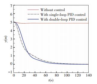
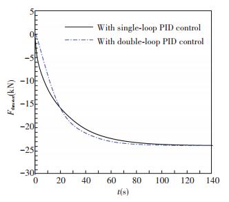
Through the tuning module, the PID parameters of the outer loop controller are Kp=0.5, Ki=0.1, Kd=0, the parameters of the inner loop controller are Kp=0.1, Ki=0, Kd=0. The response curves of lateral displacement and the lateral control force of the simulation system are shown in Figs. 5 and 6 respectively. It can be seen that the lateral displacement returns from 5 to 0 m and thrust changes from 0 to -23 847 N smoothly with thruster control in the extreme case of long tether length and large current velocity. Although the time of reaching stabilization with thruster control is a little longer than that without control, it is acceptable for the trenching operation.
|
Figure 5 Response curves of lateral displacement (l=150 m, vc=1 m/s) |
|
Figure 6 Lateral control force (l=100 m, vc=1 m/s) |
(2) Case two: Short tether length and small current velocity with l=50 m, vc=0.5 m/s.
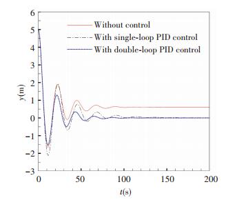
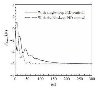
The PID parameters of the outer loop controller are tuned as Kp=0.01, Ki=0.034 5, Kd=0, the parameters of the inner loop controller are Kp=0.419, Ki=0, Kd=-2.683. From Fig. 7, the controlled lateral displacement returns from 5 to 0 m and its amplitude is smaller and time of reaching stable value is shorter than those without control. As shown in Fig. 8, thrust changes from 0 to -6 000 N with fluctuations to stabilize the trencher in the target central position in the case of strong oscillation.
|
Figure 7 Response curves of lateral displacement (l=50 m, vc=0.5 m/s) |
|
Figure 8 Lateral control force (l=50 m, vc=0.5 m/s) |
The above simulation cases show that good performances of the proposed double-loop PID controllers can be achieved. From the comparison between single-loop and double-loop PID controllers in Figs. 5-8, it can be seen that double-loop PID controller has the similar control effect with single-loop PID for slight oscillation like Case one. But for severe oscillation like case two, double-loop PID controller can get a quicker adjusting time, a smaller lateral motion amplitude and a more smooth control force. In order to meet the requirements of lateral motion control forces and satisfy the stable operation in ocean currents, eight high power hydraulic thrusters are applied on the jet trencher, and the selected thruster parameters are listed in Table 2.
| Table 2 Thruster parameters |
6 Conclusions
A mathematical model for the oscillation behavior of a jet trencher is firstly established in this paper, and an approximate analytical solution is obtained. The analytical results have small differences with numerical results based on the fourth-order Runge-Kutta which can be accepted. For this model, the analytical solution can be simple and effective to solve the problem, and result in satisfactory accuracy. The thrust system is designed to control the lateral motion displacement of the jet trencher, and the double-loop PID controller is effective and robust to make the trencher return to the central position right above the pipelines. In the future work, numerical models will be built to simulate the lateral oscillation of the trencher in the complex motion state and complex environmental condition.
| [1] |
Morrow D R, Larkin P D. The challenges of pipeline burial. Proceedings of the Seventeenth International Offshore and Polar Engineering Conference. Lisbon, Portugal: International Society of Offshore and Polar Engineers, 2007. 900-907.
( 0) 0)
|
| [2] |
Gooding S, Black K, Boyde P, et al. Environmental impact of subsea trenching operations. Proceedings of Offshore Site Investigation and Geotechnics: Integrated Technologies-Present and Future. London: Society of Underwater Technology, 2012. 213-221.
( 0) 0)
|
| [3] |
Zhang S, Zhao M, Ge T, et al. Experimental research on trenching in stiff clay by submerged vertical traveling jets.
Journal of Coastal Research, 2016, 32(2): 365-373.
DOI:10.2112/JCOASTRES-D-14-00038.1 ( 0) 0)
|
| [4] |
Hettinger F, Machin J. Cable and Pipeline Burial at 3000 Meters. Proceedings of OCEANS. Washington, 2005. 755-760.
( 0) 0)
|
| [5] |
Jukes P, Kenny S, Panapitiya U, et al. Arctic and harsh environment pipeline trenching technologies and challenges. Proceedings of OTC Arctic Technology Conference. Houston, 2011. DOI: http://dx.doi.org/10.4043/22083-MS.
( 0) 0)
|
| [6] |
Wang L, Gong H, Xing X, et al. Rigid dynamic performance simulation of an offshore pipeline plough.
Ocean Engineering, 2015, 94: 51-66.
DOI:10.1016/j.oceaneng.2014.11.004 ( 0) 0)
|
| [7] |
Brunning P, Machin J. Applications and Performance of Trenching Technologies in Asia-Pacific. Proceedings of Offshore Technology Conference Asia. Kuala Lumpur, Malaysia, 2014. DOI: http://dx.doi.org/10.4043/24833-MS.
( 0) 0)
|
| [8] |
Morgan N, Cathie D, Pyrah J, et al. Tracked subsea trencher mobility and operation in soft clays. Proceedings of the Seventeenth International Offshore and Polar Engineering Conference. Lisbon, Portugal: International Society of Offshore and Polar Engineers, 2007. 1366-1373.
( 0) 0)
|
| [9] |
Driscoll F R, Lueck R G, Nahon M. The motion of a deep-sea remotely operated vehicle system: Part 1: Motion observations.
Ocean Engineering, 2000, 27(1): 29-56.
DOI:10.1016/S0029-8018(98)00076-6 ( 0) 0)
|
| [10] |
Baddour R E, Raman-Nair W. Marine tether dynamics: retrieval and deployment from a heaving platform.
Ocean Engineering, 2002, 29(13): 1633-1661.
DOI:10.1016/S0029-8018(01)00095-6 ( 0) 0)
|
| [11] |
Driscoll F R, Lueck R G, Nahon M. Development and validation of a lumped-mass dynamics model of a deep-sea ROV system.
Applied Ocean Research, 2000, 22(3): 169-182.
DOI:10.1016/S0141-1187(00)00002-X ( 0) 0)
|
| [12] |
Zhu K Q, Zhu H Y, Zhang Y S, et al. A multi-body space-coupled motion simulation for a deep-sea tethered remotely operated vehicle.
Journal of Hydrodynamics, Ser. B, 2008, 20(2): 210-215.
DOI:10.1016/S1001-6058(08)60048-7 ( 0) 0)
|
| [13] |
Fang M C, Chen J H, Luo J H, et al. On the behavior of an underwater remotely operated vehicle in a uniform current.
Marine Technology, 2008, 45(4): 241-249.
( 0) 0)
|
| [14] |
Driscoll F R, Lueck R G, Nahon M. The motion of a deep-sea remotely operated vehicle system, Part 2: analytic model.
Ocean Engineering, 2000, 27(1): 57-76.
DOI:10.1016/S0029-8018(98)00077-8 ( 0) 0)
|
| [15] |
Lueck R G, Driscoll F R, Nahon M. A wavelet for predicting the time-domain response of vertically tethered systems.
Ocean Engineering, 2000, 27(12): 1441-1453.
DOI:10.1016/S0029-8018(99)00055-4 ( 0) 0)
|
| [16] |
Vijayan V, Panda R C. Design of PID controllers in double feedback loops for SISO systems with set-point filters.
ISA Transactions, 2012, 51(4): 514-521.
DOI:10.1016/j.isatra.2012.03.003 ( 0) 0)
|
| [17] |
Fossen T I. Guidance and control of ocean vehicles. Hoboken, NJ :John Wiley & Sons, 1994.
( 0) 0)
|
| [18] |
Li J H, Kim J T, Lee M J, et al. Conceptual design of optimal thrust system for efficient cable burying of ROV trencher. Proceedings of Oceans. St. John's, Newfoundland and Labrador: 2014. 1-5.
( 0) 0)
|
| [19] |
Astrom K J. PID Controllers: Theory, Design and Tuning. Instrument Society of America, 1995.
( 0) 0)
|
| [20] |
Chiou J C, Lin C Y, Chen C L, et al. Tilting motion control in narrow tilting vehicle using double-loop PID controller. Proceedings of the 7th Asian Control Conference. Hong Kong, China, 2009. 913-918.
( 0) 0)
|
 2017, Vol. 24


