The sustainable development of social economy depends on the reasonable use of energy and environmental protection, NG (natural gas) is a clean and highly efficient fuel and has been widely used in gas turbine power plants in recent years. Compared with coal and oil, natural gas does not produce large amount of pollution after combustion. NG is becoming one of the most important energy in 21st century. It is expected to account for about 30% of total electricity generation by 2020 compared with 17% in 2000[1].
LNG needs to be evaporated into gas at environmental temperature before fed into the gas distribution system, NG receiving stations generally use seawater as a heat source to gasify LNG. From the thermodynamic viewpoint, this process not only consumes a large amount of power for driving the seawater pump but also wastes tremendous amount of physical cold energy. With the increasing demand for cleaner fuels, LNG is now playing a significant role as an energy resource. Therefore, the utilization of the cold energy generated during LNG vaporization is becoming more vital[2]. The cold energy stored in the LNG could be recovered rather than directly taken off by seawater. Some power generation cycles utilizing low-grade heat source and the cold energy of LNG have been put forward by Hisazumi[3]. Shi and Che[4-5] proposed a combined power system, in which low-temperature waste heat can be effectively recovered and cold energy of LNG can be fully utilized as well. Liu and Guo[6] presented a novel cryogenic power cycle for LNG energy recovery, and the simulation results show that the novel power cycle has a considerably superior performance over ordinary ORC (organic Rankine cycle). Tomk[7] investigated the methods for electric energy production using cold exergy from a LNG stream, and the new improvement is proposed for an absorption power cycle by coupling it with an organic Rankine cycle.
Natural gas fired gas-steam combined cycle power plant has become popular due to its high efficiency and low emissions[8]. It is usually associated with integration of the LNG terminal and currently uses Rankine cycle as a bottoming cycle[9-10]. However, Kalina cycle showed higher exergy efficiency than that of organic Rankine cycle due to better temperature profile matching between heat source and working fluid[11-12]. Kalina cycle[13], which used ammonia-water mixture as working fluids and employs an absorption process, can efficiently work between a temperature-variable heat source and an almost isothermal heat sink. Worek[14] studied the performance of the Kalina cycle system 11 (KCS11) which was for low-temperature heat sources that were not hot enough to produce steam. Results showed that for a given turbine inlet pressure, an optimum ammonia fraction can be found that yields maximum cycle efficiency and the KCS11 had better overall performance at moderate pressures than the organic Rankine cycle. Sijun Ma et al.[15] summarized the existing evaluation criteria and proposed a new and more equitable criterion to compared the Rankine and Kalian cycles.
The research on utilizing the cold energy of LNG and Kalina cycle to enhance the efficiency of the combined power cycle with ammonia-water mixture as working fluid is quite limited. Although Miyazaki[16] established a combined power cycle using refuse incineration and LNG cold energy, which operates at Rankin cycle rather than Kalina cycle. In this paper, the system in the reference[15] is improved, the LNG is used as the heat sink rather than water and an improved combined power system is proposed based on the system. In this system waste heat can be efficiently recovered and cold energy of LNG can be fully utilized as well. The computer simulation of the power cycle is performed with Aspen Plus software, it is modelled by considering mass and energy balances for every component and thermodynamic analyses are conducted.
2 Cycle Description and FeaturesLNG is generally a mixture with typical composition[6] of N2=0.000 7, CH4=0.887 7, C2H6=0.075 4, C3H8=0.025 9, nC4H10=0.005 6, iC4H10=0.004 5, nC5H12=0.000 1, iC5H12=0.000 1, in mole fraction. Since LNG is not a pure substance, its vaporization occurs at varied temperatures. In this paper, the pressure of LNG is 3 MPa, the temperature variation characteristics of LNG is shown in Fig. 1. It indicates the vaporization process of LNG from the bubble point to the dew point.

|
Figure 1 The t -gas fraction diagram for LNG |
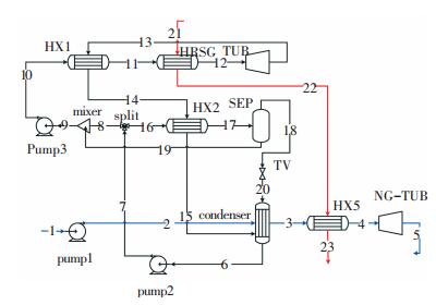
The schematic diagram of the system studied in this work is shown in Fig. 2. In the Kalina cycle, exhaust gas and LNG are used as heat source and as thermal sink, respectively. As shown in Fig. 2, a completely condensed working fluid which is the so-called “basic composition”, with parameters as at point 7, after leaving the condenser it is pumped to an intermediate pressure and attains parameters as at point 8, and then it is split into two flows. One (stream 9) absorbs the ammonia rich vapor from the top of the separator in the absorber which is cooled by the cryogenic LNG (blue line in Fig. 2) to produce the so-called “working composition”, then it is pumped to a high pressure (process 10-11) and sent into the heat exchanger1 (HX1) to be heated by the exhaust of turbine (process 11-12), then it is completely evaporated and superheated in a heat recovery steam generator (HRSG) with the heat source (process 12-13), then vapor expands through the ammonia-water vapor turbine (TUB) to generate power. The other flow (stream 16) from the split is heated in the heat exchanges (HX2, HX3 and HX4) (process16-19) and sent to the separator (SEP), where the “basic composition” is separated into a high concentration vapor (stream 20 almost pure ammonia) and a weak concentration solution (stream 22). The weak ammonia-water solution is throttled to the condensing pressure, it is mixed with the flow 15 in the condenser and becomes to the “basic composition” which is condensed to liquid (stream 7) by utilizing the cold energy released during LNG gasification process.
The LNG at a low temperature of -162 ℃ is extracted from the storage tank and pumped into the absorber. Then it is further heated in the condenser and the HX5, it becomes the superheated nature gas which pushes the NG-TUB, then the power is obtained.
The assumptions for the combined power cycle analysis are as follows:
1) The absorber and condenser are cooled by the cryogenic LNG (blue line in Fig. 2) and LNG is fed at -162 ℃, 3 MPa. At the outlet of the condenser, the “basic composition” has to be completely condensed to the bubble point and the flow rate of LNG can be determined as 235 kg/h, the minimum approaching temperature for the condenser is set to be 2 ℃. The fluid exiting the absorber is a fully liquefied solution; its temperature is equal to or less than the bubble-point temperature of the mixture.

|
Figure 2 Schematic diagram of the system |
2) In the HRSG, the outlet temperature of ammonia-water is set to be 350 ℃ which is 100 ℃ lower than the inlet temperature of heat source. The heat source which is consistent with the study[15] is a mixture with composition of N2=0.76, H2O=0.11, CO2=0.13, in mass fraction.
3) Steady-flow, steady-state process is assumed throughout the system. The system is well insulated and pressure losses are neglected.
4) Cycle parameters assumed for the simulation are given in Table 1, and the values of the parameters are taken from the Ref.[15]. Where xa and xb are mass fraction of ammonia, the subscript a means working composition, b means basic composition.
| Table 1 Cycle parameters assumed for the simulation |
The thermodynamic properties of the mixture are determined by the PengeRobinson (PR) equation and the corresponding mixing rules, which are commonly used for hydrocarbons and refrigerants in an acceptable accuracy.
3 Conventional AnalysesTable 2 summarizes the results obtained from the simulation. h means enthalpy (kJ/kg); qm means mass flow rate (kg/h); p, pressure (MPa); s, entropy (kJ/(kg·K)); x, mass fraction of ammonia; ex, specific exergy (kJ/kg); t, temperature (℃).
| Table 2 State-point of the proposed cycle |
In this study, the thermal efficiency and exergy efficiency are adopted for the cycle performance evaluation. The two efficiency definitions for the combined power cycle are given as follows:
1) Thermal efficiency. The thermal efficiency is conventionally used to evaluate the performance of a thermodynamic cycle. It is a measure of how effectively the transferred heat is converted into useful output. In this combined power cycle, the thermal efficiency is defined as the ratio of net power output to the input energy of the heat source, is given as:
| $ {\eta _1}{\rm{ = }}\frac{{{P_{{\rm{net}}}}}}{{{q_{m,w}}\left( {{h_{25}} - {h_{28}}} \right)}} $ | (1) |
where η1 represents thermal efficiency, P is power (kW), and Pnet=PTUB+PNG-TUB-Ppump1-Ppump2-Ppump3, the subscript net represents net electric power output.
2) Exergy efficiency. The definition formula of exergy efficiency is:
| $ {\eta _2} = \frac{{{E_{{\rm{gain}}}}}}{{{E_{{\rm{pay}}}}}} $ |
where η2 represents exergy efficiency, the Egain means the
| $ {\eta _2} = \frac{{{E_{{\rm{gain}}}}}}{{{E_{{\rm{pay}}}}}} $ | (2) |
where
| $ {E_{{\rm{gain}}}} = {P_{{\rm{net}}}} + {E_{x6}},{\rm{ }}{E_{{\rm{pay}}}} = {E_{x1}} + {E_{x25}}. $ |
The advantage of exergy analysis is mainly embodied in showing the direction of potential improvements. The exergy loss due to irreversibility in each component of the proposed combined cycle is estimated. It can be obtained by analyzing each component of the system separately, and then we will identify the equipment in which the main exergy destruction occurs. Estimation of exergy destruction in each component of this combined power cycle is given in Table 3. The value of exergy is affected by the choice of the reference conditions. For this work, the reference conditions are taken as t0=15 ℃ and p0=0.101 325 MPa.
| Table 3 Exergy destruction in each individual component |
In this system, the LNG is used as the thermal sink in the Kalina cycle. The temperature exergy and pressure exergy of LNG is used. The thermal efficiency of this system is η1=43.21%, the exergy efficiency of system is η2=39.76%. The thermal efficiency is ideal because of the contribution of NG-TUB, but the exergy efficiency is not high, and the next work will focus on the improvement of exergy efficiency of this system.
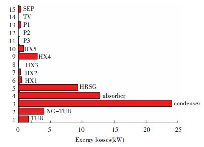
4 Analysis and ImprovementThe major exergy losses in different parts of the cycle are plotted in Fig. 3. It can be seen that the largest contribution to cycle irreversibility comes from the condenser and absorber; HRSG and HX4 also contribute significantly. It is reasonable that the heat transfer destruction is directly proportional to the transferred heat and the temperature difference between the hot and cold stream. In the heat exchanger HRSG, ammonia-water is used as working fluid, which exhibits various boiling temperature during the boiling process, thus a better thermal match can be obtained than a constant temperature boiling process, and this consequently reduces the irreversibility in the heat addition process and improves the resource utilization effectiveness. This is also the most prominent characteristic of Kalina cycle.

|
Figure 3 The major exergy losses in different parts of the cycle |
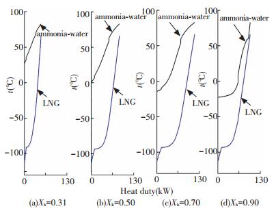
Kalina cycle does not show much merit when the thermal sink is LNG in this system. Due to the low temperature of LNG, the thermal matching between the LNG and working fluid in the condenser and absorber is not very well. But the better thermal matching can be obtained by changing mass fraction of ammonia.Fig. 4 shows the temperature distributions of the ammonia-water (upper lines) and the LNG (lower lines) in condenser for various levels of ammonia mass fraction. It can be seen the heat transfer destruction can be decreased in the condition of high mass fraction of ammonia.

|
Figure 4 Temperature distributions within condenser for various xb |
It is because the Δtm(logarithmic mean temperature difference (℃)) decreases with the increase of xb, then the exergy loss of condenser will be reduced. The Δtm in various xb is given in Table 4.
| $ \Delta {t_{\rm{m}}} = \frac{{\Delta {t_{{\rm{max}}}} - \Delta {t_{{\rm{min}}}}}}{{\ln \frac{{\Delta {t_{{\rm{max}}}}}}{{\Delta {t_{{\rm{min}}}}}}}} $ | (3) |
| Table 4 Δtm with various xb |
There Δtmax and Δtmin represent the maximum and minimum values of temperature difference of cold and hot fluid in the import and export of the condenser.
Improvements can be performed from the above analysis, on the basis of above system; a new cycle is established in the Aspen Plus. It is presented in the Fig. 5, this system consists of the Kalina cycle with ammonia-water mixture as the working fluid and a LNG power generation cycle. There are some differences compared with the previous system.

|
Figure 5 Schematic diagram of the improved system |
1) In the previous system, the absorber is necessary to cool the stream to the temperature which is bubble point or lower. But the absorber is no longer required because the stream 8 is mixed with weak ammonia-water solution (stream 19) from the bottom of the separator to produce a so-called “working composition” (stream 9), with a totally liquid state. So there is the mixer replacement.
2) In the Kalina cycle, as shown in Fig. 5, a completely condensed working fluid of a so-called “basic composition”, with a higher concentration of ammonia (xb=0.74) compared with the previous system. The separation temperature has to be reset due to the change of “basic composition”. In this system, the separation temperature is set to be 45 ℃.
3) In the previous system, the separation temperature is 89 ℃ so the heat exchanger (HX2 and HX3) can be set to preheat the inflow of separation. But the HX2 and HX3 are eliminated because of its low heat transfer contribution in the improved system.
4) In this new system, the temperature of“basic composition” from the condenser is -16.3 ℃ which is much lower than the previous system (27.4 ℃), because the temperature of bubble point is decreased with the increase of xb. The stream 14 rather than the stream 22 is used to preheat the inflow of separation, it is because the temperature difference between the stream 22 and 16 in the heat exchanger is very high so that the irreversibility could be increased.
5) The ammonia rich vapor from the top of the separator rather than the weak ammonia-water solution from the bottom of the separator is throttled to the condenser, it is mixed with the flow 15 in the condenser and then the mixed flow is condensed to the “basic composition” with higher composition by utilizing the cold energy released during LNG gasification process. A relatively satisfied thermal matching between the LNG and working fluid can be obtained in the condenser on account of the increase of concentration of “basic composition”.
The assumptions for the combined power cycle analysis are the same with the previous system. The calculated thermodynamic parameters for each state of the new system are summarized in Table 5.
| Table 5 State-point of the improved system |
5 Results and Discussion
Table 6 gives the simulation results of the two cycles to compare the performances under two different systems. This improved system can generate a power of 44.17 kW and the thermal efficiency of the system can reach about 42.83%. It can be seen the power of kalina cycle in the two systems is equal. Obviously, the contribution of NG-Turbine (TUB2) is slightly different, and the thermal efficiency is almost the same.
| Table 6 Simulation results of the two cycles |
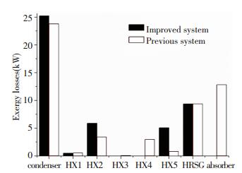
The exergy efficiency of the improved system is higher than the previous system. The exergy losses mainly exist in the heat transfer process in the system and the improvement is carried out based on the heat exchanger. So the major exergy losses in different heat exchanger of the cycle under previous system condition and improved system condition are obtained and plotted in Fig. 6.

|
Figure 6 Comparison of exergy losses in the various heat exchanger of the cycle |
It can be found that the exergy loss of improved system in the condenser is a little higher than the previous system. It is because that the inlet temperature of LNG is different, the inlet temperature of LNG is much lower in the improved system, so it increases the irreversibility in the condenser, but we increased the xb, so the influence can be decreased. The exergy loss of HX2 in the improved system is higher than that in the previous because of the higher temperature difference between hot and cold streams. But HX3 and HX4 are deleted in the improved system, so the exergy losses in this heat exchanger can be reduced and the system is easier. The total exergy losses in HX2, HX3 and HX4 of the previous system are higher than that in improved system. The exergy loss of HX5 is higher in the improved system because of the higher temperature difference between hot and cold streams. But it does not occupy a large proportion of the total exergy losses, and the remove of absorber highly contributes the increase of exergy efficiency. In general, the exergy efficiency is increased because of irreversibility decrease of various heat exchangers.
6 ConclusionsThis paper improves the combined power system using the Kalina cycle, exergy efficiency of previous system is not high, so an improved system is carried out, which can effectively recover waste heat of exhaust gas and fully utilize the cold energy of LNG as well. The power output can be dramatically increased due to the contribution of LNG power cycle. The results show that an exergy efficiency of 42.97% can be obtained. Compared with the previous system which attains exergy efficiency of 39.76%, the system has a better performance.
It can be seen the Kalina cycle generally used at the bottom of combined power cycle could also be reorganized and used to recover the cold energy of LNG. The use of LNG in the combined power cycle can not only increase power output of the system but also save a great amount of electrical power for driving sea water pump because sea water is no longer required as the heat source to vaporize the LNG. The vaporized natural gas that has an ambient temperature and pressure is useful products which can be sent to the user or as the fuel of gas fired power station.
In order to further evaluate the advantages of the improved combined system and determine if this system is profitable, a more detailed design and an optimization study based on the results of thermodynamic analyses are expected.
| [1] |
Griepentrog H, Tsatsaronis G, Morosuk T. LNG Vaporization Using a Novel Co-Generation System. Proceedings of the ASME 2008 International Mechanical Engineering Congress and Exposition, USA: ASME, 2008.
( 1) 1)
|
| [2] |
Kim T S, Ro S T. Power augmentation of combined cycle power plants using cold energy of liquefied natural gas.
Energy, 2000, 25(9): 841-856.
DOI:10.1016/S0360-5442(00)00018-9 ( 1) 1)
|
| [3] |
Hisazumi Y, Yamasaki Y, Sugiyama S. Proposal for a high efficiency LNG power-generation system utilizing waste heat from the combined cycle 1.
Applied Energy, 1998, 60(3): 169-182.
DOI:10.1016/S0306-2619(98)00034-8 ( 1) 1)
|
| [4] |
Shi Xiaojun, Che Defu. A combined power cycle utilizing low-temperature waste heat and LNG cold energy.
Energy Conversion & Management, 2009, 50(3): 567-575.
DOI:10.1016/j.enconman.2008.10.015 ( 1) 1)
|
| [5] |
Wang Huan, Shi Xiaojun, Che Defu. Thermodynamic optimization of the operating parameters for a combined power cycle utilizing low-temperature waste heat and LNG cold energy.
Applied Thermal Engineering, 2013, 59(1/2): 490-497.
DOI:10.1016/j.applthermaleng.2013.05.048 ( 1) 1)
|
| [6] |
Liu Yanni, Guo Kaihua. A novel cryogenic power cycle for LNG cold energy recovery.
Journal of Engineering Thermophysics, 2012, 36(5): 2828-2833.
DOI:10.1016/j.energy.2011.02.024 ( 2) 2)
|
| [7] |
Tomk W Ł, Cholewiński M. Improvement of the LNG (liquid natural gas) regasification efficiency by utilizing the cold exergy with a coupled absorption-ORC (organic Rankine cycle).
Energy, 2015, 87(6): 45-53.
DOI:10.1016/j.energy.2015.05.041 ( 1) 1)
|
| [8] |
Poullikkas A. An overview of current and future sustainable gas turbine technologies.
Renewable & Sustainable Energy Reviews, 2005, 9(5): 409-443.
( 1) 1)
|
| [9] |
Shi Xiaojun, Che Defu. Thermodynamic analysis of an LNG fuelled combined cycle power plant with waste heat recovery and utilization system.
International Journal of Energy Research, 2007, 31(10): 975-998.
DOI:10.1002/er.1293 ( 1) 1)
|
| [10] |
Lv Shuangshuang. Simulation and Optimization of the Liquefied Natural Gas Cold Energy Stored and Recovery Process. Dalian: Dalian University of Technology, 2014.
( 1) 1)
|
| [11] |
Marston C H. Parametric analysis of the Kalina cycle.
Journal of Engineering for Gas Turbines & Power, 1990, 112(1): 107-116.
DOI:10.1115/89-GT-218 ( 1) 1)
|
| [12] |
Nag P K, Gupta A V S S K S. Exergy analysis of the Kalina cycle.
Applied Thermal Engineering, 1998, 18(6): 427-439.
DOI:10.1016/S1359-4311(97)00047-1 ( 1) 1)
|
| [13] |
Kalina A I. Combined-cycle system with novel bottoming cycle.
Journal of Engineering for Gas Turbines & Power, 1984, 106(4): 737-742.
DOI:10.1115/1.3239632 ( 1) 1)
|
| [14] |
Hettiarachchi H D M, Golubovic M, Worek W M, et al. The performance of the Kalina cycle system 11(KCS11) with low-temperature heat sources.
Journal of Energy Resources Technology, 2007, 129(3): 243-247.
DOI:10.1115/1.2748815 ( 1) 1)
|
| [15] |
Ma Sijun, Jing Xuye, Li Xiaoxiao, et al. Thermodynamic analysis and comparison between rankine and kalina cycles with ammonia-water mixture working fluids.
Zhongguo Dianji Gongcheng Xuebao, 2014, 34(2): 288-294.
DOI:10.13334/j.0258-8013.pcsee.2014.02.011 ( 4) 4)
|
| [16] |
Miyazaki T, Kang Y T, Akisawa A, et al. A combined power cycle using refuse incineration and LNG cold energy.
Energy, 2000, 25(7): 639-655.
DOI:10.1016/S0360-5442(00)00002-5 ( 1) 1)
|
| [17] | Hasan A A, Goswami D Y, Vijayaraghavan S. First and second law analysis of a new power and refrigeration thermodynamic cycle using a solar heat source. Solar Energy, 2002, 73(5): 385-393. DOI:10.1016/S0038-092X(02)00113-5 |
| [18] | Vijayaraghavan S, Goswami D Y. On evaluating efficiency of a combined power and cooling cycle. Journal of Energy Resources Technology, 2003, 125(3): 221. DOI:10.1115/IMECE2002-33308 |
| [19] | Cihan A, Hachafizoglu O, Kahveci K. Energy-exergy analysis and modernization suggestions for a combined-cycle power plant. International Journal of Energy Research, 2006, 30(2): 115-126. DOI:10.1002/er.1133 |
| [20] | Lior N, Zhang Na. Energy, exergy, and second law performance criteria. Energy, 2007, 32(4): 281-296. DOI:10.1016/j.energy.2006.01.019 |
 2017, Vol. 24


