High quality aluminum alloy automobile body sheet (ABS), especially automobile outer panel, is the top level products in aluminum alloy strips due to its complex production process, special production equipment, high surface quality and other technical requirements, and its requirement exceeds supply at present[1-3]. Air-cushion furnace is the key equipment for the production of ABS and high-grade aviation plate, because only using which high surface quality, high mechanical properties, high performance consistency, stability and high efficiency can be obtained[4-5]. Floating furnace air flows through special nozzles to form "air pad" between strip and nozzles, which can make the strip floating. Hot air is used for solid solution or aging treatment, while cold air is used for rapid cooling. Air-cushion nozzle is the key component of floating furnace, whose structure and control parameters are very important to realize aluminum strip floating and uniform heating or cooling.
Air-cushion devices have been applied widely to the transportation equipment and industrial production. Jaumotte and Kiedrzynski[6], Mair[7], Alexander[8], Obrzut[9], Crewe and Eggington[10] established thin or thick jet models for hovercraft and air-cushion transport equipment. Chang and Moretti[11] analyzed the effect principles of various air-cushion equipment and corrected air cushion mural boarder theoretical formula according to the theoretical derivation and simple exploratory experiment verification. Renard[12] studied the effects of air-cushion furnace structure and jet velocity on strip vibration using reduced scale model, and compared with the vibration data of SIDGAL steel galvanizing line 3. Cho[13] established simplified model of air-cushion equipment of strip vibration under high-speed air stream, which is regarded as motile model with certain tension. Yang and Chang[14] conducted numerical simulation of aerodynamic characteristic of pressure-pad air bars for printing drying. Kramer[15] introduced air jet floating technique of air cushion for cooling in the stainless steel strip heat treatment line. Chen[16] studied the mechanism of dynamic pressure and static pressure nozzle based on school laboratory small air-cushion furnace test equipment. Li[17] studied the vibration characteristics of coupling system composed of steel strip and air cushion in continuous hot-dip galvanizing processes. Hou[18] studied the round nozzle' floating force and heat transfer character of air cushion furnace.
Heat treatment of ABS and high-grade aviation plate must have zero surface defect and strict temperature uniformity, that is, Al strip must float more stably, air-cushion pressure field and temperature field must be more uniform, but there are less researches on the aerodynamics characteristics and flow field of air-cushion furnace.
To solve this problem, the new large geometric model was set up according to the actual size of air-cushion furnace equipment of ABS, using k-ε turbulence equations of COMSOL Multiphysics to perform high accurate flow field numerical simulation. The influence and regularity of number, diameter and arrangement of middle hole, and main control parameters of new air-cushion nozzle on aerodynamic characteristics and flow field were studied. And a new air-cushion jet theory model for ABS air-cushion furnace was set up through theoretic deduction and simulation and lab test data correction. This study is valuable for improving the air-cushion stability, Al strip temperature homogeneity, and temperature control precision.
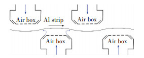
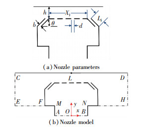
2 Air-Cushion Nozzle Numerical Analysis Model and Fluid Control EquationsFig. 1 shows Al strip floats in air-cushion furnace. Fig. 2(a) shows the air-cushion nozzle parameters and Fig. 2(b) shows the numerical analysis model. Where n is the number of middle holes; d is the diameter of hole; θ is the slit nozzle tilt angle; b is the slit nozzle opening; Lj is the slit length; Xj is the distance between the slits; h is the floating height; line CD stands for Al strip.
|
Figure 1 Al strip floating in air-cushion furnace |
|
Figure 2 Air-cushion nozzle parameters and model |
Air jet from air-cushion to Al strip is a process of high Reynolds numbers flow, and is simulated using k-ε interface of COMSOL Multiphysics, which is suitable for incompressible flows, and compressible flows at low Mach number (typically less than 0.3). The Turbulent Flow, k-ε interface are used to solve the Navier-Stokes equations for conservation of momentum and the continuity equation for conservation of mass. Turbulence effects are simulated by using the standard two-equation k-ε model with realizability constraints[19]. Flow close to walls is simulated by using wall functions. Turbulent Flow, k-ε interface are as follows:
| $ \begin{array}{l} \rho \left( {\mathit{\boldsymbol{u}} \cdot \nabla } \right)\mathit{\boldsymbol{u}} = \nabla \cdot \left[ { - p\mathit{\boldsymbol{I + }}\left( {\mu + {\mu _{\rm{T}}}} \right)\left( {\nabla \mathit{\boldsymbol{u}} + {{\left( {\nabla \mathit{\boldsymbol{u}}} \right)}^{\rm{T}}}} \right) - } \right.\\ \;\;\;\;\;\;\;\;\;\;\;\;\;\;\;\;\;\;\left. {\frac{2}{3}\left( {\mu + {\mu _{\rm{T}}}} \right)\left( {\nabla \cdot \mathit{\boldsymbol{u}}} \right)\mathit{\boldsymbol{I}} - \frac{2}{3}\rho k\mathit{\boldsymbol{I}}} \right] + \mathit{\boldsymbol{F}} \end{array} $ | (1) |
| $ \nabla \cdot \left( {\rho \mathit{\boldsymbol{u}}} \right) = 0 $ | (2) |
| $ \rho \left( {\mathit{\boldsymbol{u}} \cdot \nabla } \right)k = \nabla \cdot \left[ {\left( {\mu + \frac{{{\mu _{\rm{T}}}}}{{{\sigma _k}}}} \right)\nabla k} \right] + {p_k} - \rho \varepsilon $ | (3) |
| $ \rho \left( {\mathit{\boldsymbol{u}} \cdot \nabla } \right)\varepsilon = \nabla \cdot \left[ {\left( {\mu + \frac{{{\mu _{\rm{T}}}}}{{{\sigma _k}}}} \right)\nabla \varepsilon } \right] + {C_{e1}}\frac{\varepsilon }{k}{p_k} - {C_{e2}}\rho \frac{{{\varepsilon ^2}}}{k} $ | (4) |
| $ {\mu _{\rm{T}}} = \rho {C_\mu }\frac{{{k^2}}}{\varepsilon } $ | (5) |
| $ {p_k} = {\mu _{\rm{T}}}\left[ {\nabla \mathit{\boldsymbol{u}}:\left( {\nabla \mathit{\boldsymbol{u}} + {{\left( {\nabla \mathit{\boldsymbol{u}}} \right)}^{\rm{T}}}} \right) - \frac{2}{3}{{\left( {\nabla \cdot \mathit{\boldsymbol{u}}} \right)}^2}} \right] - \frac{2}{3}\rho k\nabla \cdot \mathit{\boldsymbol{u}} $ | (6) |
where u is velocity field, u={u, v, w}; p is pressure; k is turbulent kinetic energy; ε is turbulent dissipation rate, and turbulence model parameters: Ce1=1.44, Ce2=1.92, Cμ=1, σk=1, σe=1.3.
In Fig. 2(b), CD is the aluminum strip. Airflow flows from AB boundary into the air bar, then emits from the left and right slit nozzles. Airflow forms an air cushion between two slit nozzles and aluminum strip, which provides a support for aluminum strip. This model makes inlet center of nozzle box as coordinate origin.
Line AB is the air flow entrance boundary, and U0 is normal inflow velocity, inlet equations are as follows:
| $ u = - {U_0}n $ | (7) |
| $ k = \frac{3}{2}{\left( {{U_{{\rm{ref}}}}{\mathit{\boldsymbol{I}}_{\rm{T}}}} \right)^2},\varepsilon = C_\mu ^{3/4}\frac{{{k^{3/2}}}}{{{L_{\rm{T}}}}},{U_{{\rm{ref}}}} = {U_0} $ | (8) |
Here, It is turbulence intensity; LT is turbulence length scale.
Line EFand GH are outlet boundaries, pressure is p0, outlet equations are as follows:
| $ \begin{array}{l} \left[ { - p\mathit{\boldsymbol{I + }}\left( {\mu + {\mu _{\rm{T}}}} \right)} \right.\left( {\nabla \mathit{\boldsymbol{u}} + {{\left( {\nabla \mathit{\boldsymbol{u}}} \right)}^{\rm{T}}}} \right) - \frac{2}{3}\left( {\mu + } \right.\\ \left. {\left. {{\mu _{\rm{T}}}} \right)\left( {\nabla \cdot \mathit{\boldsymbol{u}}} \right)\mathit{\boldsymbol{I}} - \frac{2}{3}\rho k\mathit{\boldsymbol{I}}} \right]n = - {{\hat p}_0}n \end{array} $ | (9) |
| $ {{\hat p}_0} \le {p_0},\nabla k \cdot n = 0,\nabla \varepsilon \cdot n = 0 $ |
The lines in the curve of CEMABNHD of Fig. 2 are set as interior walls.
In order to ensure the accuracy of the calculation results, special mesh refining treatment is conducted according to the characteristics of the flow field simulation, especially near the wall and the slit nozzles. The largest cell size is 2.68 mm, and the smallest is 0.008 mm. The growth rate of the largest cell is 1.05. The relative tolerance of solver is set as 0.001.
3 Analysis of Air-cushion Nozzle Aerodynamics and Flow Field CharacteristicsAccording to the real size of Al strip floating furnace, set CD=1 000 mm, AB=400 mm, EM=NH=300 mm, b=10 mm, Lj=60 mm, θ=60°, Xj=400 mm. The distance of top and bottom air-cushion box is usually 200 mm, floating height region is from 70 mm to 130 mm in general, so h takes 100 mm. pc is air-cushion pressure; pc is the average of it; pt is the pressure in the air-cushion nozzle box; vin is the airflow velocity of entrance boundary AB; pt can be detected and controlled, we change vin to make pt change. h is decided by the pressure difference of bottom and top air-cushion, strip weight, and strip tension, but the tension usually is tiny, so the first two factors are major factors. In the production, we control pc by controlling pt. The influence and regularity of number, diameter and arrangement of middle holes, and main control parameters of new air-cushion nozzle on aerodynamic characteristics and flow field were studied in detail as follows.
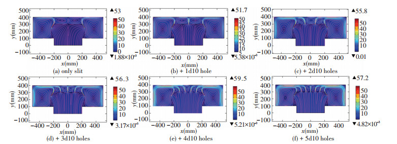
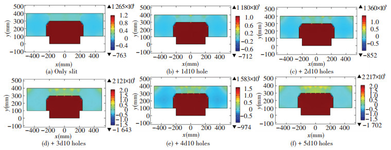
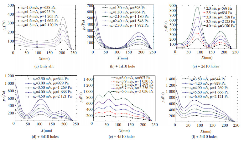
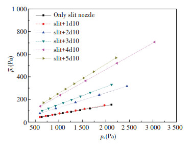
3.1 Effect of Holes NumbersSet n=0, 1, 2, 3, 4, 5, d=10 mm, and vin is variable. Fig. 3 shows the simulated velocity distribution and velocity vector map, and Fig. 4 shows the pressure nephogram. Fig. 5 shows the air pressure distribution along the aluminum strip LD line. Fig. 6 shows the relationship between pc and pt under different n. As can be seen, 1) With n increases, airflow vortex in air-cushion area increases in multiple, the number of airflow vortex is equal to 2(1+n) in general, and the size of the airflow vortex becomes closer, which shows the air-cushion is more stable, and velocity distribution is more uniform. 2) Average of pc is proportional to pt, when n increases, the ratio of average of pc to pt increases. 3) When d is the same, n is larger, air-cushion is more uniform, and the even number is better than the odd number.
|
Figure 3 Velocity distribution and velocity vector map |
|
Figure 4 Pressure nephogram |
|
Figure 5 Air pressure along the aluminum strip surface lien LD |
|
Figure 6 Relationship between pc and pt under different n |
3.2 Optimization of Air-cushion Nozzle with Even Number Holes and its Aerodynamic Characteristics
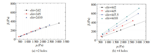
Set n=2, 4, d=10 mm, 5 mm, 2 mm, and vin is variable. Figs. 7 and 8 are the air pressure distribution along the aluminum strip line LD of n=2 and n=4, respectively. Fig. 9 shows the relationship between pc and pt. As can be seen, 1) With d decreases and n increases, pc becomes uniform; 2) When pt increases, non-uniformity of pc increases, but if d is small, the effect is wake; 3) pc is proportional to pt, when n=2, d has little effect on the pc/pt, but n=4, d has larger effect. So, adding even number in the middle of air-cushion nozzle can improve the uniformity of pc, when n=4, pc/pt is relatively large and the uniformity of pc is relatively good. When d≤b/2, the uniformity of pc is relatively good.

|
Figure 7 Air pressure along the aluminum strip surface lien LD when n=2 |

|
Figure 8 Air pressure along the aluminum strip surface lien LD when n=4 |
|
Figure 9 Relationship between pc and pt |
3.3 Optimization of Air-cushion Nozzle with Odd Number Holes and its Aerodynamic Characteristics
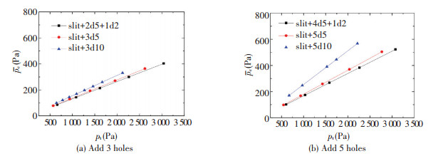
Set n=3, 5, d=10 mm, 5 mm, 2 mm, and vin is variable. Figs. 10 and 11 are the air pressure distribution along the aluminum strip line LD of n=3 and n=5, respectively. Fig. 12 is the relationship between pc and pt. As can be seen, 1) With d decreases, pc becomes uniform; 2) the center hole affects the uniform of pc greatly, and center d deceases, the uniformity of pc is obviously improved; 3) when pt increases, non-uniformity of pc increases, but if d is small, the effect is weak; 4) pc is proportional to pt, when d is small, and d has little effect on pc/pt. So adding an odd number in the middle of air-cushion nozzle can improve the uniformity of pc, when d≤b/2 and center d is smaller, uniformity of pc is better.

|
Figure 10 Air pressure along the aluminum strip surface lien LD when n=3 |

|
Figure 11 Air pressure along the aluminum strip surface lien LD when n=5 |
|
Figure 12 Relationship between pc and pt |
4 Discussion and Novel Air-cushion Nozzle Model 4.1 Discussion
The classical thin jet model of air-cushion is shown as follows[11], which can be deduced by using momentum equation to slit jet flow[20].
| $ {p_{\rm{c}}} = \rho v_j^2\left( {1 + \cos \theta } \right)\frac{b}{h} $ | (10) |
| $ \frac{{{p_{\rm{c}}}}}{{{p_t}}} = \frac{{2\left( {1 + \cos \theta } \right)}}{{h/b + 1 + \cos \theta }} $ | (11) |
The air-cushion pressure is supposed symmetrically in the classical thin jet model of air-cushion, so here, pc equals to the average of air-cushion pressure along the Al strip surface above (pc). pt is the effective total pressure (gage pressure) of the air jet after the nozzle, which is the pressure in the air-cushion nozzle box. This model assumes that the thickness of jet flow is much smaller than the flotation height b/h < < 1), the thickness of jet flow does not change along the path of the jet, the flow profile across the jet is uniform, the jet speed does not change along the path of the jet, the path of the jet flow has a constant curvature and is tangent to the ground, and the pressure in the region surrounded by the two streams of air jet is constant[21]. When (b/h)(1+cos θ)>1, Eq.(11) predicts a cushion pressure higher than the total pressure of the air jet. As an extreme case, when the flotation height approaches zero, Eq.(11) predicts pc/pj=2.
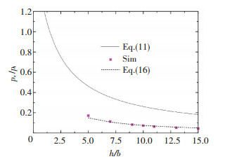
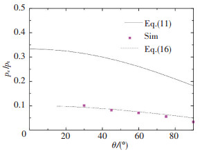
The deviation between simulation data (the 'Sim' points in Figs. 13 and 14) and the above model is very large, and the average deviation between simulation and Eq.(11) is -71.54% when θ equals 60° and h/b equals 5 to 15, and -70.97% when θ equals 30° to 75° and h/b equals 10. So these conventional air jet models are all vastly overrate air-cushion pressure, which agrees with the research results of Richarson[22], Crewe and Eggington[10]. The reason is probably that the air-cushion jet models assume that the fluid is inviscid, ignoring the coanda viscosity loss of the gas energy. At the same time, pt is the total effective pressure at the slit outlet of the air bar in models, which is different with air pressure in jet box of the simulation.
|
Figure 13 Relationship between pc/pt and h/b (θ=60°) |
|
Figure 14 Relationship between pc/pt and θ(h/b=10) |
4.2 A New Air-cushion Nozzle Model
Therefore, it is necessary to develop an air jet model suitable for air-cushion of Al strip floating furnace. A new air-cushion model is deduced as follows, which considers air viscous loss.
In Fig. 2, the air flows in from AB, at the velocity of vin, flows out from the cross section of slit nozzle outlet at the velocity of vj. The pressure at AB is pt, the pressure at the cross section of slit nozzle outlet is p1. Applying Bernoulli equation[20], we can obtain:
| $ {p_t} + \frac{{\rho v_{{\rm{in}}}^2}}{2} = {p_1} + \frac{{\rho v_{\rm{j}}^2}}{2} $ | (12) |
Because the pressure and the fluid velocity are small, according to mass conservation derived:
| $ {v_{{\rm{in}}}}\frac{{{X_{\rm{j}}}}}{2} = {v_{\rm{j}}}b $ | (13) |
Given by Eqs.(12) and (13), we can get:
| $ {v_{\rm{j}}} = \sqrt {\frac{{2\left( {{p_{\rm{t}}} - {p_1}} \right)}}{{\rho \left[ {1 - {{\left( {2b/{X_{\rm{j}}}} \right)}^2}} \right]}}} $ | (14) |
For air-cushion nozzle of the air-flotation ovens, pl is much smaller than pt, and thus the effect ofplcan be ignored. Meanwhile, considering the viscosity loss along the way caused by the jet box wall, k is assumed to be the velocity coefficient, k < 1, Eq.(14) becomes:
| $ {v_{\rm{j}}} = k\sqrt {\frac{{2{p_{\rm{t}}}}}{{\rho \left[ {1 - {{\left( {2b/{X_{\rm{j}}}} \right)}^2}} \right]}}} $ | (15) |
Combined with Eq.(10), we obtain:
| $ \frac{{{p_{\rm{c}}}}}{{{p_t}}} = \frac{{2{k^2}\left( {1 + \cos \theta } \right)}}{{1 - {{\left( {2b/{X_{\rm{j}}}} \right)}^2}}}\frac{b}{h} $ | (16) |
For only slit nozzle, k takes 0.5, the average deviation of simulation and new model data is -3.34% when θ equals 60° and h/b equals 5 to 15, and 4.77% when θ equals 30° to 75° and h/b equals 10, as shown in Figs. 13 and 14. When the air-cushion are added many holes in the middle area between the two silt, k is corrected correspondingly, and the comparison of new model and simulation data are shown in Table 1, and the average deviation of simulation and new model data is within±7.75%.
| Table 1 k and comparison of new model and simulation data |
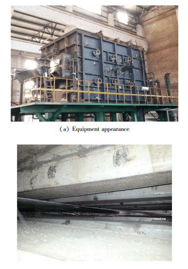
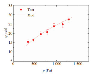
By using the large-scale laboratory floating furnace equipment, the relationship between pt and the velocity of the slit nozzle outlet (vj) is tested. The test equipment length is 6 800 mm, width 4 800 mm, and height 9 400 mm, as shown in Fig. 15. The thickness of test Al strip is 1.0 mm, width 1 400 mm, and tension 3 215 N. The parameters of air-cushion nozzle are: d=5 mm, n=4, or 5 (the even and odd staggered arrangement), b=9 mm, θ=60°, Xj=400 mm, h=100 mm, ttair=22 ℃. vj is measured by using Janpon KANOMAX KA23 hot wire anemometer, and pt is measured by using U type tube pressure gauge. The deviation of experimental equipment test data and the new model is between -4.75% and 7.76%, as shown in Fig. 16. These prove that the new air-cushion model preferably reflects the aerodynamics characteristics of Al strip floating furnace.
|
Figure 15 Air-cushion furnace test equipment |
|
Figure 16 Test data and new model |
5 Conclusions
1) As the number of holes in middle area of newair-cushion nozzle increases, airflow vortex in air-cushion area increases in multiple, the air-cushion is more stable, and velocity distribution is more uniform; d decreases, pc becomes uniform and when d≤b/2, uniform of pc is good; Average of pc is proportional to pt, when n increases, ratio of average of pc to pt increases. When n≤3 and d < b/2, they have little effect on ratio of pc average to pt.
2) To the uniformity of pc: When d is the same, the larger of n, the better of the uniformity, and the even number is better than the odd number; when d decreases or n increases, pc becomes uniform; when n is an even number, n≥4, and d≤b/2, uniformity of pc is good; when n is an odd number, the center hole affects pc uniformity greatly, and when the diameter of center hole is less than b/4 and the diameter of non-center is between b/4 and b/2, uniformity of pc is good.
3) A new air-cushion jet model is presented, because the conventional model is only used for nozzle without holes, and greatly overestimates pc, which does not consider air viscous loss. The average deviation of simulation data and new model is -3.34% when θ equals 60° and h/b equals 5 to 15, and 4.77%, when θ equals 30° to 60° and h/b equals 10. The deviation of large floating furnace experimental equipment data and new model is within±7.75%. These prove that the new air-cushion model preferably reflects the aerodynamics characteristics of Al strip floating furnace. That is valuable for improving the air-cushion stability, Al strip temperature homogeneity, and temperature control precision.
| [1] |
Prillhofer R, Rank G, Berneder J, et al. Property criteria for automotive Al-Mg-Si sheet alloys.
Materials, 2014, 7(7): 5047-5068.
DOI:10.3390/ma7075047 ( 0) 0)
|
| [2] |
Hirsch J R. Aluminium in innovative light-weight car design.
Materials Transactions, 2011, 52(5): 818-824.
DOI:10.2320/matertrans.L-MZ201132 ( 0) 0)
|
| [3] |
Sakurai T. The latest trends in aluminum alloy sheets for automotive body panels.
Kobelco Technology Review, 2008(28): 22-28.
( 0) 0)
|
| [4] |
Li Y, Wang Z D, Ma M T, et al. Air cushion furnace technology for heat treatment of high quality aluminum alloy auto body sheet.
Engineering, 2014, 12(5): 73-80.
DOI:10.15302/J-ENGI-2014016 ( 0) 0)
|
| [5] |
Wang X F, Guo M X, Yong C L, et al. Effect of heating rate on mechanical property, microstructure and texture evolution of Al-Mg-Si-Cu alloy during solution treatment.
Materials Science & Engineering, 2015, 621(A): 8-17.
DOI:10.1016/j.msea.2014.10.045 ( 0) 0)
|
| [6] |
Jaumotte A, Kiedrzynski A. Theory and experiments on air cushion vehicles at zero speed.
Hovering Craft Hydrofoils, 1965, 4: 4-25.
( 0) 0)
|
| [7] |
Mair W A. The physical principles of hovercraft.
Hovering Craft Hydrofoils, 1964, 4(3): 5-13.
( 0) 0)
|
| [8] |
Alexander A J. The momentum equation for the hovercraft at zero incidence.
J. R. Aeronaut. Soc., 1966, 70: 363.
DOI:10.1017/S036839310008233X ( 0) 0)
|
| [9] |
Obrzut J J. Coil coaters float strip through ovens.
Iron Age, 1976, 218(22): 31-33.
( 0) 0)
|
| [10] |
Crewe P R, Eggington W J. The hovercraft-a new concept in maritime transport.
Trans. R. Inst. Naval Arch., 1960, 102: 315-356.
( 0) 0)
|
| [11] |
Chang Y B, Moretti P M. Aerodynamic characteristics of pressure-pad air bars.
Journal of Applied Mechanics, 2000, 1(67): 177-182.
DOI:10.1115/1.321161 ( 0) 0)
|
| [12] |
Renard M, Gouriet J B, Buchlin J M. Rapid cooling in continuous annealing and galvanizing lines.
Revue de Metallurgie, 2003(8): 751-756.
DOI:10.1051/metal:2003157 ( 0) 0)
|
| [13] |
Cho H K. Flow-Induced Vibration of a Web Floating Over a Pressure-Pad Air Bar. Seoul: Bachelor of Science Konkuk University Seoul, 2005.
( 0) 0)
|
| [14] |
Yang S H, Young C B, Chang K W. Analysis on aerodynamic characteristics of drying process in R2R printed electronics.
Journal of the Korean Society of Precision Engineering, 2010, 27(3): 95-103.
( 0) 0)
|
| [15] |
Kramer C, Hansen M. Gas jet floatation for the touchless cooling of sensitive stainless steel strips in strip annealing lines.
Heat Processing, 2006, 4(1): 24-26.
( 0) 0)
|
| [16] |
Chen W X, He Y H, Liu F S, et al. A study gas dynamics process in air cushion furnace of continuous heat treatment for metal plate-strip.
J. Cent. South Inst. Min. Metall, 1987, 18(2): 145-230.
( 0) 0)
|
| [17] |
Li L L, Cai Z Q, Hui S, et al. Vibration analysis characteristics of coupling system composed of steel strip and air cushion in continuous hot-dip galvanizing processes.
Mechanical Science and Technology for Aerospace Engineering, 2015(04): 526-532.
( 0) 0)
|
| [18] |
Hou S, Li Y, Wang Z D, et al. Study on round nozzle' floating force and heat transfer character of air cushion furnace.
Industrial Furnace, 2013, 41(3): 1-4.
( 0) 0)
|
| [19] |
Wang F J.
Computational fluid dynamics analysis-the principle and application of CFD. Beijing: Tsinghua University Press, 2004.
( 0) 0)
|
| [20] |
Finnemore E J, Franzini J B. Fluid mechanics with engineering applications. Translated by Qian Yi Ji and Zhou Yu Wen. 10th ed. Beijing: China Machine Press, 2013.
( 0) 0)
|
| [21] |
Davies M J, Wood D H. The basic aerodynamics of flotation.
ASME J. Fluids Eng., 1983, 105: 323-328.
DOI:10.1115/1.3240998 ( 0) 0)
|
| [22] |
Richardson H H, Ribich W A, Ercan Y. Pressure-flow-displacement characteristics of a peripheral jet fluid suspension, 76110-7. MIT, 1968.
( 0) 0)
|
 2017, Vol. 24


