With the development and improvement of IR imaging guidance, the traditional infrared decoy can rarely plays a role in the infrared counter measure[1-3]. Meanwhile, A new surface-type infrared decoys, such as MJU-50B armed in US air force, are developed to prevent the IR imaging guidance missile seeker from locking on and lure the missile away from target platform.
As shown in Fig. 1, this type of surface-type infrared decoy works differently from the traditional decoy. About a thousand plates are loaded side by side in the shrapnel shell. Each plate is only a few tenths of millimeter thick and painted with spontaneous combustion material. Thousands of plates are launched in the atmosphere simultaneously and spread in the high-speed airstream, as well as combusted as an infrared cloud. The coverage area of the cloud can usually reach in 2 000 m2[4].The corresponding researches on this type of decoy have been carried out by lots of researchers and experts. Most of the scholars generally deal with the plates cloud by assuming that the plates are treated as particles and the plates cloud is uniform globular[5] or normal[6] distributed. However, the plate is a cylinder with low length-to-diameter ratio (the ratio is 0.002), which is not suitable for the particle model. In this paper, the infrared characteristic of the plates cloud is simulated on the basis of 6-DOF rigid body model and fluid dynamic method[4, 7]. The attitude and the opposite position of each plate are computed numerically and the shadow effect of the plates cloud is also considered. Thus, the new method in this work is more reasonable.

|
Figure 1 Diagrammatic sketch of surface-type infrared decoy |
Besides, the operational principle of the surface-type infrared decoy is different from that of the traditional decoy, the surface-type decoy has a lower combustion temperature and shorter combustion time than the traditional type decoy (the combustion time of the surface-type is 2 s-3 s while that of the traditional type is generally more than 6 s)[8-9]. In order to enhance the interferential effects, pilots always launch more than one surface-type infrared decoy simultaneously or at an interval. Hence, the capability of jamming and the optimization of the launching method to utilize the new type of decoy is the main object of this study.
2 Numerical Method and Model 2.1 Dispersion Model of the Plate CloudThe infrared plate cloud is made up with thousands of plates and each plate is an independent radiation source. In order to simulate the radiation intensity of the infrared cloud, the attitude and the opposite position of each plate must be computed numerically. The theoretical model of fluid-solid coupling is established to simulate the dispersion process of thousands of plates, and the detailed theoretical method has been carried out in former work[4, 7].
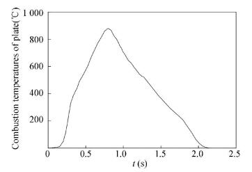
2.2 Radiance Model of the Plate CloudThe plate is plastered with special pyrophoric substance[10-13], and begins to combust once it is launched from the aircraft, and its radiation characteristics is close to exhaust plume. The temperature of the plates was measured by the single plate combustion experiment. Fig. 2 illuminates the variation of the temperature of the plates during the combustion experiment.
|
Figure 2 Variation of combustion temperatures of plate in experiment |
The total radiation intensity of the plate involves the self-emitted radiation and the reflected radiation of the environment (such as solar radiation, atmosphere radiation, ground radiation). For that the combustion temperature of the plate when it works is more than 400 ℃, the self-emitted radiation of the plate is much higher than the reflected radiation of the environment. Thus, the reflected radiation of the environment is neglected in this work.
According to the Stefan-Boltzmann law[5, 14-16], the self-emitted radiation intensity of the single plate in whole waveband is
| $ {E_b} = \int_0^\infty {{\varepsilon _\lambda }} \frac{{{c_1}}}{{{\lambda ^5}\left[{\exp \left( {\frac{{{c_2}}}{{\lambda T}}} \right)-1} \right]}}{\rm{d}}\lambda $ | (1) |
where ελ is the spectral emissivity; c1, c2 is the Stefan-Boltzmann constant; λ is the wavelength of spectrum and T is the temperature of the plate.
For the infrared tracking missiles, the response waveband range of the sensor is usually in 3 μm-5 μm and 8 μm-14 μm band. Thus, the self-emitted radiation in [λ1, λ2] band can be expressed as
| $ {M_{{\lambda _1}- {\lambda _2}}} = \int_{{\lambda _1}}^{{\lambda _2}} {{\varepsilon _\lambda }\frac{{{c_1}}}{{{\lambda ^5}\left[{\exp \left( {\frac{{{c_2}}}{{\lambda T}}} \right)-1} \right]}}{\rm{d}}\lambda } $ | (2) |
The plate is considered as a gray body, and its spectral emissivity is assumed to be a constant ελ=0.8. The temperature of each plate is considered to be uniform distribution. Thus, the actual radiation intensity of a single plate that the missile sensor received is
| $ I = {M_{{\lambda _1}-{\lambda _2}}}A\cos \;\alpha $ | (3) |
where A is the plate's area; α is the angle between the plate and the missile.
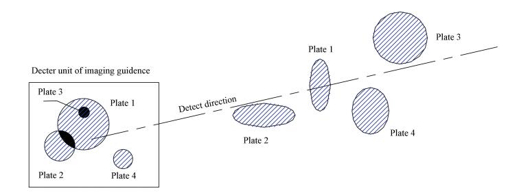
A surface-type infrared decoy usually loads about 1 000 plates. When the plates are launched, the plates are projected to the plane of detector. And the projected diagrammatic sketch of the 3 kinds of the plated is shown in Fig. 3. From Fig. 3, some plates are partly overlapped while some are fully shaded. The plate in the plates cloud can be divided into 3 cases: plate fully detected (plate 4 as shown in Fig. 3), plate partly detected (plates 1 and 2 as shown in Fig. 3) and plate fully shaded (plate 3 as shown in Fig. 3).
|
Figure 3 The computing model of cover coefficient φ |
The projected area of each plate can be calculated. Thus, the sum area S1 of the projected area of each plate is obtained. Considering the shadow effect of the plates cloud, the variable φ is defined to be the percentage of the projected areas which is not shaded and can be calculated by
| $ \varphi = \frac{{{S_2}}}{{{S_1}}} $ | (4) |
where S2 is the projected areas which is not shaded.
Thus, the total radiation intensity is expressed as
| $ {I_{{\rm{all}}}} = \varphi \sum\limits_1^n {{I_n}} $ | (5) |
where In is the radiation intensity of plate n.
3 Results and Discussion 3.1 Dispersion and Radiation Intensity of the Plate CloudWhen the imaging guidance missile is tracking aircraft, the pixel number of target in infrared images is in dependence on the distance between missile and target. Various of target-tracking algorithm and tracking modes were utilized by the imaging guidance according to the pixel number of target in infrared images and listed in Table 1[1, 5, 17].
| Table 1 Guidance mode and tracking algorithm of guidance in different distance |
The simulation conditions are set as follows [5, 18]: the distance of aircraft and missile is 4 km at the initial time and the missile attacks the aircraft from the back or one side; the speed of the aircraft is 240 m/s and the launching speed of surface-type infrared decoy is 35 m/s; the pixels of the imaging sensor is 128×128 and the angular field of view is 4°. Thus, the infrared images at different time and different directions are simulated based on the condition above. The radar images of infrared cloud of a single surface-type infrared decoy are shown in Figs. 4-11. The distance between missile and aircraft is from 4 km to 0.5 km and the detecting directions are side detection and back detection.

|
Figure 4 The images of plates cloud in imaging radar on attack of missile from side at distance of 4 km |

|
Figure 5 The images of plates cloud in imaging radar on attack of missile from back at distance of 4 km |

|
Figure 6 The images of plates cloud in imaging radar on attack of missile from side at distance of 2 km |

|
Figure 7 The images of plates cloud in imaging radar on attack of missile from back at distance of 2 km |

|
Figure 8 The images of plates cloud in imaging radar on attack of missile from side at distance of 1 km |

|
Figure 9 The images of plates cloud in imaging radar on attack of missile from back at distance of 1 km |

|
Figure 10 The images of plates cloud in imaging radar on attack of missile from side at distance of 0.5 km |

|
Figure 11 The images of plates cloud in imaging radar on attack of missile from back at distance of 0.5 km |
It can be obviously concluded from Figs. 4-11 that the infrared cloud can be recognized as a point interference source when the distance of aircraft and missile is larger than 4 km.The energy central position of the infrared cloud and aircraft is listed in Table 2 based on the assumption that the aircraft flies in a beeline. The image guidance is attracted to track the energy central of cloud which has the higher radiation intensity. With reduction of distance between the missile and aircraft, more number of pixels of plates cloud can be recognized by the missile sensor and the missile tracking mode will translate to imaging guidance mode. Moreover, the area of steady plate cloud would be about 1 000 m2 from any direction while the area of the plume and jets of aircraft is usually less than 20 m2. Thus, the plume and jets of aircraft can be easily covered by the plate cloud. The infrared image of plate cloud blends with that of aircraft and interferes the tracking of the missile. Hence, the aircraft can more effectively to get rid of tracking by imaging guidance radar.
| Table 2 Energy center of plate cloud compared with the coordinate of aircraft while decoys launched at various distances of aircraft and missile |
Additionally, image recognition is the most important method for the imaging guidance radar to recognize aircraft and decoy, and the infrared feature is also a critical judgment for imaging guidance missile.
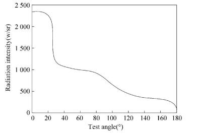
Fig. 12 shows the schematic diagram of infrared radiation intensity of a typical military aircraft [17]. The radiation intensity of the aircraft is different from different directions. In addition, due to the effect of the high temperature of the plume and jets, the backward infrared radiation intensity of aircraft is far stronger than that from forward direction or sidewise.
|
Figure 12 Radiation intensity of a typical military aircraft |
Generally, the temperature of the nozzle at a jet engine is about 900 K. If the target is a two-motor military aircraft, the radiation intensity of the jet nozzle is about 500 W/sr-3000 W/sr [19-20].Therefore, the radiation intensity of the infrared decoy should be twice higher than that of the military aircraft to transfer the energy central position to the plate cloud. Thus, the radiation intensity is also a key parameter of the interference capability of a surface-type infrared decoy.
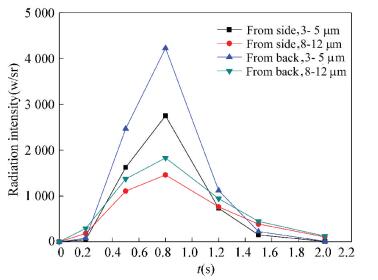
Fig. 13 shows the variation of the infrared radiation intensity of plates cloud. It is obvious that the effective working time of surface-type infrared decoy is about 2 s, and the radiation intensity is large enough to attract the imaging guidance missile in most of the working time. However, one single decoy can not absolutely meet the demand of war. Thus, multiple launching is necessary to strengthen the ability in Infrared Counter-Measure.
|
Figure 13 Variation of radiation intensity of surface-type infrared decoy by simulation |
3.2 Effect of Multiple Launching on the Properties of the Surface-Type Infrared Decoy
The infrared decoy is the last refuge of aircraft and multiple launching is an effective way to increase the interference capability of the infrared decoy. There are three general methods of multiple launching: launching at a fixed interval, launching several decoys simultaneously and launching the all on the verge of the emergency.
3.2.1 Launching at a fixed intervalLaunching decoys at a fixed interval is a general method for the continuous launching. In this way, several plate clouds overlap and connect in the sky, and the vision of the enemy missile may be mostly covered by the clouds. As a result, the probability of lure the missile away is increased.
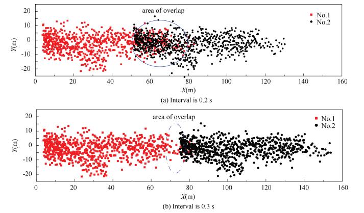
Fig. 14 illuminates the dispersion of adjacent plate clouds which is launched at different intervals. As shown in Fig. 14, the difference appears in X coordinate when the interval is 0.3 s and 0.2 s, respectively. When the interval is 0.3 s, the plates cloud No.1 and No.2 meet at the boundary. There is just a small part of the area of plate clouds coinciding with each other. However, as shown in Fig. 15, the dispersion of a single plates cloud is concentrated in the head and sparse at the rear. Thus, an area of low radiation intensity from 60 m to 80 m exits.
|
Figure 14 The dispersion of two plates cloud in X-coordinate at the interval of 0.2s and 0.3s |

|
Figure 15 The dispersion of single plates cloud in X-coordinate |
When the interval is 0.2 s, the adjacent plate clouds coincide with each other from 55 m to 80 m. The concentrated area of plate cloud No.2 in the head makes up the sparse area of plate cloud No.1 at the rear. In this case, the total area of plate cloud becomes smaller compared to the case of 0.3 s, but the adjacent plates cloud have better quality of continuity and also own better jamming effect at the same time. Therefore, 0.2 s is a better choice as the launching interval.
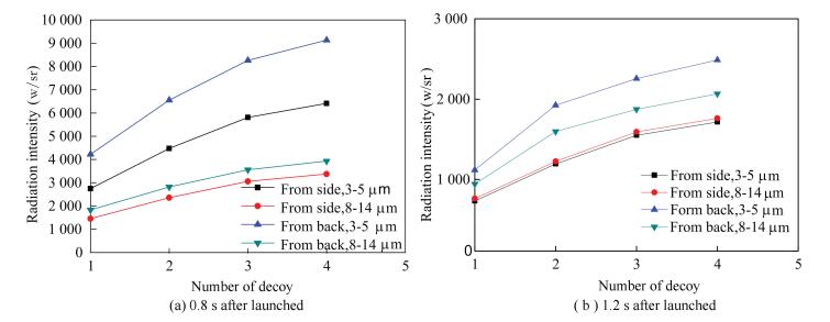
3.2.2 Launching in a volleyLaunching decoys in a volley is launching several infrared decoys simultaneously. The guidance missile prefers to track the target with stronger radiation intensity. Launching several decoys simultaneously increases the number of plates per unit area. Thus, the radiation intensity and the RCS (Radar Cross-Section) are also increased with the number of plates. As a consequence, the probability to lead the guide missile tracking the infrared cloud is increased. Fig. 16 shows the radiation intensity of the infrared cloud with different number of surface-type decoys after launched 0.8 s and 1.2 s.
|
Figure 16 Curves of radiation intensity of plates cloud by different number decoy launched simultaneously |
As shown in Fig. 16, launching decoys simultaneously can increase the radiation intensity of plates cloud effectively. For launching two decoys at the same time, the radiation intensity of plates cloud is about 1.5 times compared with that of single. While for the case of four decoys, the radiation intensity of plates cloud is increased to about two times comparing with that of single.
It can be concluded from the result that the radiation intensity of the plate cloud is not the multiple relationship with the number of decoys, as the overlapping coefficient of the plates is increased with the increase of the plate density and the number of the decoys. To interfere the guidance of the missile effectively and low costly, pilots could choose a suitable number of decoys according to the type of missile.
4 ConclusionsIn this paper, based on the calculation of distribution of plates cloud and test of the temperature of a single plate, the radar imagery of infrared cloud is simulated and analyzed at different times after surface-type decoy was launched. The result shows that the surface-type infrared decoy not only can be recognized as a point interference source when the missile is remote tracking. Moreover, the plume and jets of aircraft can be covered by the plates cloud and the infrared image of plate blends with that of aircraft when the missile is on infrared imaging guide model. It is an effectively way to interfere the tracking of the infrared imaging guidance missile.
With the analysis of the plate cloud dispersion at different intervals and the infrared radiation intensity in the case of different launching number, it can be concluded that a comfortable launching interval can maintain a continuous plate cloud, launching the decoys simultaneously increase the increment of the radiation intensity obviously, the multiple launching is an effective way to enhance the interference property of the decoy.
| [1] |
Chen Ning, Wan Chun, Huang Feng. Interference availability of IR surface-type decoy.
Aerospace Electronic Warfare, 2012, 28(6): 38-42.
( 0) 0)
|
| [2] |
Gan Yuanliu, Jiang Chong, Liu Yujie, et al. Development of foreign airborne IR decoy technology.
Electro-Optic Technology Application, 2013, 28(6): 13-18.
( 0) 0)
|
| [3] |
Shi Xiaohua, Zhang Tonghe. The counter-countermeasure technology for dual-band multi-element IR seeker.
Infrared Technology, 2009, 31(6): 311-314.
( 0) 0)
|
| [4] |
Wang Zhengwei, Ning Huijun, Wang Jinlong, et al. Simulation and analysis of plates cluster distribution of surface-type infrared decoy.
Acta Armamentarii, 2015, 36(6): 994-1000.
( 0) 0)
|
| [5] |
Fu xiaohong, Fan Qiulin. Research on modeling and simulation of special material decoy.
Electro-Optic Technology Application, 2013(6): 81-86.
( 0) 0)
|
| [6] |
Zhao Feiyu, Lu Shan, Jiang Chong. Research on the modeling method of surface-type infrared decoy.
Electro-Optic Technology Application, 2012, 27(2): 66-69.
( 0) 0)
|
| [7] |
Wang Zhengwei, Ruan Wenjun, Wang Hao. Simulation of plates group initial separation in high speed.
Acta Aerodynamica Sinica, 2015, 33(6): 828-834.
( 0) 0)
|
| [8] |
Chen Bin, Zeng Xingzhi, Liu Caihong. Analysis of infrared guided missile’s interference signal.
Computer and Information Technology, 2013, 21(3): 13-16.
( 0) 0)
|
| [9] |
Tong Qi, Li Jianxun, Fang Yangwang. Simulation research on surface-type infrared decoy for jamming infrared imaging guided missile.
Infrared and Laser Engineering, 2015, 44(4): 1150-1157.
( 0) 0)
|
| [10] |
Lin Hongxue, Zhu Chengguang, Jiang Xiaonan. Study on the design of low-temperature infrared decoy and its combustion properties.
Infrared Technology, 2013, 35(10): 654-658.
( 0) 0)
|
| [11] |
Lin Hongxue. Performance Study on Materials of Film-type Decoy with Low Combustion Temperature. Nanjing:Nanjing University of Science and Technology, 2014.
( 0) 0)
|
| [12] |
Wang Xin. Study of technique characteristics of array IR decoy and composition of materials.
Electro-Optic Technology Application, 2007, 22(3): 11-13.
( 0) 0)
|
| [13] |
Lv Xiangyin, Huang Chaochao, Ling Yongshun. Analysis on surface-type infrared decoy for jamming infrared imaging guidance.
Electronic Warfare Technology, 2004, 19(5): 41-45.
( 0) 0)
|
| [14] |
Yang Dongsheng, Dai Guanzhong. Radiation simulation of the characteristics of infrared flares.
Science Technology and Engineering, 2011(21): 5104-5110.
( 0) 0)
|
| [15] |
Yang Dongsheng, Sun Siliang, Dai Guanzhong. Infrared image simulation of an aircraft based on its three-dimensional model.
Journal of Northwestern Polytechnical University, 2010, 28(5): 758-763.
( 0) 0)
|
| [16] |
Incropera F P, Dewitt D P.
Fundamentals of Heat and Mass Transfer. Beijing: Chemical Industry Press, 2007.
( 0) 0)
|
| [17] |
Kong Xiaoling, Ma Shengxian, Du Yuping, et al. Simulation research on surface-type infrared decoy for jamming infrared imaging guided missile.
Command Control & Simulation, 2011, 22(1): 78-81.
( 0) 0)
|
| [18] |
Tian Xiaofei, Ma Lihua, Hong Hua. Study on jamming characteristic and simulation of surface-type infrared decoy.
Laser & Infrared, 2012, 42(2): 165-169.
( 0) 0)
|
| [19] |
Niu Luwei, Dong Jingxuan. Research on jamming effectiveness of airborne infrared bait by simulation.
Computer Simulation, 2013, 30(12): 21-24.
( 0) 0)
|
| [20] |
Li Yanzhi, Sun Bo, Wang Dahui. Building model of aeroplane infrared radiant and Simulation.
Infrared Technology, 2008, 30(5): 252-255.
( 0) 0)
|
 2017, Vol. 24


