Research on Variable Structure and Adaptive Control for Strap-on Rocket
1 Introduction Compared with launch vehicles in active service, the major characteristic of the solid strap-on rock is that it straps on four solid boosters. A solid booster has the advantages of large thrust, simple structure and convenient operation. It can significantly increase the launching capacity of rock, but at the same time it also brings four problems to the design of the control system. Firstly, the unique configuration leads to the disadvantages of an excessively large angle of attack, excessively large thrust misalignment, and lack of synchronism, which result in the increase of structural disturbance to the rock. Secondly, the design of this configuration and large-diameter fairing will significantly increase the normal aerodynamic coefficient. Meanwhile, in order to reduce the pressure center-centroid distance, installing a tail on the boost is considered, which will further increase the normal force coefficient and resistance coefficient, while an increase of the coefficient will cause the same level of wind to undergo larger normal disturbing force and disturbance torque, so that the maximum transverse load of the rock will also become larger under the combined action. Thirdly, as this type of rock has a complicated configuration, the problems such as parameter uncertainties and unmodeled dynamics, etc. shall be considered in the establishment of attitude dynamics model. Finally, the control effect of the rolling channel is influenced by the pitching channel and yaw channel, and undergoes the coupling phenomenon, which will cause difficulty to the design of control system[1]. The above factors will deteriorate the stability of the control system, increase the design difficulty of the control system, enhance the strength of the rocket structure, increase the rocket weight, and decrease the launching capability.
Considering that the sliding mode possesses complete self-adaptability[2], meeting the reachability conditions sliding form can guarantee stable sliding motion and good system dynamic performance[3]. At the same time, the sliding mode has complete invariance to the system parameter perturbation[4] and strong robustness to the larger external disturbance[5-6], so that the sliding mode can be used to design the attitude control system for the solid strap-on rocket. As the adaptive control does not depend on the accurate model of the controlled object, but rather makes real-time adjustment of the control parameters according to the changes of the parameters and indicators, so as to allow the system to operate at an optimum or near optimal state[7], it is applicable to solve the problems of the solid strap-on rocket, such as the parameter uncertainties, unmodeled dynamics, etc. The variable structure adaptive design method (namely adopting the adaptive switching gain method) can effectively reduce the buffeting, and guarantee that when the uncertain factors are bounded, the motion of the uncertain system beginning from a random initial state must enter and become stable in the dummy sliding mode domain within a limited period of time. Use of the adaptive switching gain will not influence the robustness or stability of the variable structure control system[8]. The variable structure adaptive method has a relatively simple structure and can adjust the parameters according to physical significance, while it also has a simple algorithm which will be convenient for the project's realization[9].
This paper establishes the dynamics deviator model for the solid strap-on rocket, proposes the adaptive control method for the sliding mode variable structure on the basis of the model reference after considering the large structural disturbance and external disturbance to the rocket, as well as the uncertainties of model parameters and unmodeled dynamics, and uses the Lyapunov function to prove the global asymptotic stability of the system. The theoretical analysis and simulation show that the control method proposed in this paper can guarantee the system attitude stability.
2 Dynamical Model
2.1 Deviator Model of Attitude Dynamics The dynamical system core stage of the solid strap-on rocket studied in this paper is configured with two engines, and simultaneously straps on four solid rocket motors. The motors can realize bidirectional swinging to control the pitching and yaw channels. This paper only considers the large attitude change at the pitching direction when the yaw angle and roll angle are both small. In accordance with the demands of problem analysis, this paper gives the rocket centroid dynamics, dynamics equation around the centroid, Euler angle conversion equation, and deviator equation for the angular conversion. The centroid dynamics equation is as follows:
|
$
\begin{array}{l}
\Delta \dot \theta = c_{3xj}^\varphi \Delta {\delta _{{\varphi _{xj}}}} + c_{3xj}^{''\varphi }\Delta {{\ddot \delta }_{{\varphi _{xj}}}} + c_{3zt}^\varphi \Delta {\delta _{{\varphi _{zt}}}} + c_{3zt}^{''\varphi }\Delta {{\ddot \delta }_{{\varphi _{zt}}}} + \\
\;\;\;\;\;\;c_{10}^\varphi \left( {\Delta \alpha + {\alpha _w}} \right) - {{\bar F}_{yc}} + c_2^\varphi \Delta \theta
\end{array}
$
|
(1) |
|
$
\begin{array}{l}
\Delta \dot \sigma = c_{3xj}^\psi \Delta {\delta _{{\psi _{xj}}}} + c_{3xj}^{''\psi }\Delta {{\ddot \delta }_{{\psi _{xj}}}} + c_{3zt}^\psi \Delta {\delta _{{\psi _{zt}}}} + c_{3zt}^{''\psi }\Delta {{\ddot \delta }_{{\psi _{zt}}}} + \\
\;\;\;\;\;\;c_{10}^\psi \left( {\Delta \beta + {\beta _w}} \right) - {{\bar F}_{zc}} + c_2^\psi \Delta \sigma
\end{array}
$
|
(2) |
The dynamics equation around the centroid is:
|
$
\begin{array}{l}
\Delta {{\dot \omega }_x} + {d_{3xj}}\Delta {\delta _{{\gamma _{xj}}}} + {{d''}_{3xj}}\Delta {{\ddot \delta }_{{\gamma _{xj}}}} + {d_{3zt}}\Delta {\delta _{{\gamma _{zt}}}} + {{d''}_{3zt}}\Delta {{\ddot \delta }_{{\gamma _{zt}}}} = \\
\;\;\;\;\;\;{{\bar M}_x}
\end{array}
$
|
(3) |
|
$
\begin{array}{l}
\Delta {{\dot \omega }_y} + b_1^\psi \Delta {\omega _y} + b_2^\psi \left( {\Delta \beta + {\beta _w}} \right) + b_{3xj}^\psi \Delta {\delta _{{\psi _{xj}}}} + \\
\;\;\;\;\;\;b_{3xj}^{''\psi }\Delta {{\ddot \delta }_{{\psi _{xj}}}} + b_{3zt}^\psi \Delta {\delta _{{\psi _{zt}}}} + b_{3zt}^{''\psi }\Delta {{\ddot \delta }_{{\psi _{zt}}}} = {{\bar M}_y}
\end{array}
$
|
(4) |
|
$
\begin{array}{l}
\Delta {{\dot \omega }_z} + b_1^\varphi \Delta {\omega _z} + b_2^\varphi \left( {\Delta \alpha + {\alpha _w}} \right) + b_{3xj}^\varphi \Delta {\delta _{{\varphi _{xj}}}} + \\
\;\;\;\;\;\;b_{3xj}^{''\varphi }\Delta {{\ddot \delta }_{{\varphi _{xj}}}} + b_{3zt}^\varphi \Delta {\delta _{{\varphi _{zt}}}} + b_{3zt}^{''\varphi }\Delta {{\ddot \delta }_{{\varphi _{zt}}}} = {{\bar M}_z}
\end{array}
$
|
(5) |
where
|
$
\begin{array}{*{20}{c}}
{{{\bar M}_x} = {M_{x0}} + {M_{co}}}\\
{{M_{co}} = d_4^\alpha \Delta \alpha + d_4^\beta \Delta \beta + d_5^{{\omega _y}}\Delta {\omega _y} + d_5^{{\omega _z}}\Delta {\omega _z}}
\end{array}
$
|
(6) |
The Euler angle transfer equation is:
|
$
\Delta \dot \gamma = \Delta {\omega _x}
$
|
(7) |
|
$
\Delta \dot \psi = \Delta {\omega _y}
$
|
(8) |
|
$
\Delta \dot \varphi = \Delta {\omega _z}
$
|
(9) |
The angular conversion equation is:
|
$
\Delta \alpha = \Delta \varphi - \Delta \theta
$
|
(10) |
|
$
\Delta \beta = \Delta \psi - \Delta \sigma
$
|
(11) |
The inclination (sideslip) angle is:
|
$
\begin{array}{l}
{\alpha _w} = {\tan ^{ - 1}}\left[ {W\cos \left( {{A_w} - {A_0}} \right)\sin \theta /\left( {V + W\cos \left( {{A_w} - } \right.} \right.} \right.\\
\;\;\;\;\;\left. {\left. {\left. {{A_0}} \right)\cos \theta } \right)} \right]
\end{array}
$
|
(12) |
|
$
{\beta _w} = {\tan ^{ - 1}}\left( {W\sin \left( {{A_w} - {A_0}} \right)/V} \right)
$
|
(13) |
In the dynamics equations, φ, ψ and γ are respectively the pitching, yaw and roll angle; θ and σ are respectively the trajectory inclination angle and trajectory deflection angle; α, β, αw and βw are respectively the angle of attack, the angle of sideslip, wind attach angle and wind sideslip angle; ωx, ωy and ωz are the attitude angle velocities; δxj and δzt are respectively the core-stage deflection angle and boosting deflection angle; c3xjφ, c3ztφ, $ {c^{\prime \prime }}_{3xj}^\varphi $, ${c^{\prime \prime }}_{3zt}^\varphi $, c3xjψ c3ztψ, $ {c^{\prime \prime }}_{3xj}^\psi $ and ${c^{\prime \prime }}_{3zt}^\psi $ are the force coefficients caused by the control force and inertia force; c10φ and c10ψ are the aerodynamic coefficients; b1φ and b1ψ are the aerodynamic damping torque coefficients; b2φ and b2ψ are the aerodynamic lift coefficients; b3xjφ, b3ztφ, b3xjψ, b3ztψ, d3xj, d3zt, ${b^{\prime \prime }}_{3xj}^\varphi $, ${b^{\prime \prime }}_{3zt}^\varphi $, ${b^{\prime \prime }}_{3xj}^\psi $, $ {b^{\prime \prime }}_{3zt}^\psi $, $ d_{3xj}^{^{\prime \prime }}$ and $ d_{3zt}^{^{\prime \prime }}$ are the moment coefficients caused by the control force and inertia force; $ {{\bar F}_{yc}}$ and $ {{\bar F}_{zc}}$ are the disturbing force coefficients; ${{\bar M}_x}$, ${{\bar M}_y} $ and ${{\bar M}_z} $ are the disturbance moment coefficients. Among these, Mco is the disturbance caused by the channel coupling. The definitions of other coefficients of the attitude dynamics equations are shown in Ref.[10].
2.2 Disturbance and Disturbance Torque During flight, rocket suffers a great deal of disturbance and disturbance torque. In order to research rocket accurately, the disturbance model of the rocket has been built as follows:
1) Supposed that ηi represents deflection of thrust line, disturbance and torque caused by deflection of thrust line are
|
$
{F_{d1}} = k \cdot {P_i}{\eta _i}
$
|
(14) |
|
$
{M_{d1}} = k \cdot {P_i}{\eta _i}\left( {{x_{{R_i}}} - {x_Z}} \right)
$
|
(15) |
2) Supposed that △Z represents sidesway of centroid, then disturbance and torque are
|
$
{M_{d2}} = {P_i}\Delta Z
$
|
(16) |
3) Supposed that △εi represents sidesway of thrust line, then disturbance and torque are
|
$
{M_{d3}} = k \cdot {P_i}\Delta {\varepsilon _i}
$
|
(17) |
4) Supposed that △α1 represents installation error of rocket axis, disturbance and torque caused by deflection of rocket axis are
|
$
{F_{d2}} = 57.3C_y^\alpha q{S_{xj}}\Delta {\alpha _1} + 57.3\sum\limits_{i = I}^{IV} {C_{{y_i}}^\alpha q{S_{zt}}\Delta {\alpha _1}}
$
|
(18) |
|
$
{M_{d4}} = - {b_2}{J_{{Z_1}}}\Delta {\alpha _1}
$
|
(19) |
5) Supposed that △αwyirepresents installation error of empennage, then disturbance and torque are
|
$
{F_{d3}} = 57.3\sum\limits_{i = I}^{IV} {C_{w{y_i}}^\alpha q{S_{w{y_i}}}\Delta {\alpha _{w{y_i}}}}
$
|
(20) |
|
$
{M_{d5}} = 57.3\sum\limits_{i = I}^{IV} {C_{w{y_i}}^\alpha q{S_{w{y_i}}}\left( {x_{w{y_i}}^p - {x_Z}} \right)\Delta {\alpha _{w{y_i}}}}
$
|
(21) |
6) Supposed that installation error of core stage is δExj, disturbance caused by thrust deflexion is
|
$
{F_{d5}} = \frac{{\sqrt 2 }}{2}\Delta {P_{xj}}{\delta _{Exj}}
$
|
(22) |
Disturbance torque is
|
$
{M_{d61}} = \frac{{\sqrt 2 }}{2}\Delta {P_{xj}}\left[ {{r_1} - \left( {{x_{{R_{xj}}}} - {x_Z}} \right){\delta _{{E_{xj}}}}} \right]
$
|
(23) |
Disturbance torque caused by thrust deflexion of booster is
|
$
{M_{d62}} = \Delta {P_{zt}}r
$
|
(24) |
The complex disturbance torque is
|
$
{M_{d6}} = \sqrt {M_{d61}^2 + M_{d62}^2}
$
|
(25) |
7) Disturbance and disturbance torque caused by asynchronism of thrust
Due to the nonuniformity of burning and the deflection of powder charge, asynchronism of thrust is inevitable in three cases. In the first case, four solid boosters have different accelerations during ignition. In the second case, rated thrust of solid booster is slightly different in process of rated operation of solid booster. Lastly, thrust of one solid booster declines earlier than other solid boosters during the process of booster turn-off. Above three cases generate disturbance and disturbance torque which exert a negative impact on attitude control system of rocket. Referred to technical indicator of solid booster, this article concentrates on the most serious situation that leads to increase of drift in takeoff phase and where thrust of two boosters in the symmetrical location is zero and thrust of other two boosts declines in sequence.
In the disturbance model, when discussing about core unit, i represents xj and value of k is 2. Meanwhile, i means zt and k equals to 4 when discussing about booster unit.Pi is thrust. △Pi is thrust deflexion coefficients. Sxj, Szt and Swyi are characteristic area. Cyα and Cwyiα are lift force coefficients. xwyip, xZ and xRi are the locations of centre of pressure of empennage, centroid and swing point of engine.JZ1 is rotational inertia. q means pressure corresponding fight altitude. r is the distance from centre of booster to rocket axis and r1 is the distance from centre of core stage to rocket axis. All three channels are influenced by disturbance and disturbance torque mentioned above. In this paper, Mx, My and Mz mean disturbance torque for three channels and Fx, Fy and Fz mean disturbance.
2.3 State Space Form In order to facilitate discussion, the rocket attitude dynamics equation can be converted to the state space form in the primary flight phase, and only the posture alignment of pitching will be made for the rocket. When the yaw angle and roll angle are both small, we select the engineering measurable attitude angle and attitude angle velocity, as well as the trajectory inclination angle and trajectory deflection angle as the input state of the system, as follows:
|
$
\mathit{\boldsymbol{x = }}{\left[ {\begin{array}{*{20}{c}}
{\Delta \theta } & {\Delta \sigma } & {\Delta \dot \varphi } & {\Delta \varphi } & {\Delta \dot \psi } & {\Delta \psi } & {\Delta \dot \gamma } & {\Delta \gamma }
\end{array}} \right]^{\rm{T}}}
$
|
(26) |
Selecting the attitude angle as the output state as follows:
|
$
\mathit{\boldsymbol{y}} = {\left[ {\begin{array}{*{20}{c}}
\varphi & \psi & \gamma
\end{array}} \right]^{\rm{T}}}
$
|
(27) |
And implement the derivation of Eqs. (8) and (9) and sort out Eq. (1) into Eq.(13) to obtain:
|
$
\begin{array}{l}
\mathit{\boldsymbol{\dot x = Ax + Bu + Df}}\\
\left[ {\begin{array}{*{20}{c}}
{\Delta \dot \theta }\\
{\Delta \dot \sigma }\\
{\Delta \ddot \varphi }\\
{\Delta \dot \varphi }\\
{\Delta \ddot \psi }\\
{\Delta \dot \psi }\\
{\Delta \ddot \gamma }\\
{\Delta \dot \gamma }
\end{array}} \right] = \left[ {\begin{array}{*{20}{c}}
{{c_2} - {c_1}} & 0 & 0 & {{c_1}} & 0 & 0 & 0 & 0\\
0 & {{c_2} - {c_1}} & 0 & 0 & 0 & {{c_1}} & 0 & 0\\
{{b_2}} & 0 & { - {b_1}} & { - {b_2}} & 0 & 0 & 0 & 0\\
0 & 0 & 1 & 0 & 0 & 0 & 0 & 0\\
0 & {{b_2}} & 0 & 0 & { - {b_1}} & { - {b_2}} & 0 & 0\\
0 & 0 & 0 & 0 & 1 & 0 & 0 & 0\\
0 & 0 & 0 & 0 & 0 & 0 & 0 & 0\\
0 & 0 & 0 & 0 & 0 & 0 & 1 & 0
\end{array}} \right]\left[ {\begin{array}{*{20}{c}}
{\Delta \theta }\\
{\Delta \sigma }\\
{\Delta \dot \varphi }\\
{\Delta \varphi }\\
{\Delta \dot \psi }\\
{\Delta \psi }\\
{\Delta \dot \gamma }\\
{\Delta \gamma }
\end{array}} \right] + \\
\left[ {\begin{array}{*{20}{c}}
{c_{3xj}^\varphi } & {c_{3zt}^\varphi } & 0 & 0 & 0 & 0\\
0 & 0 & {c_{3xj}^\psi } & {c_{3zt}^\psi } & 0 & 0\\
{ - b_{3xj}^\varphi } & { - b_{3zt}^\varphi } & 0 & 0 & 0 & 0\\
0 & 0 & 0 & 0 & 0 & 0\\
0 & 0 & { - b_{3xj}^\psi } & { - b_{3zt}^\psi } & 0 & 0\\
0 & 0 & 0 & 0 & 0 & 0\\
0 & 0 & 0 & 0 & { - {d_{3xj}}} & { - {d_{3zt}}}\\
0 & 0 & 0 & 0 & 0 & 0
\end{array}} \right]\left[ {\begin{array}{*{20}{c}}
{{\delta _{\varphi xj}}}\\
{{\delta _{\varphi zt}}}\\
{{\delta _{\psi xj}}}\\
{{\delta _{\psi zt}}}\\
{{\delta _{\gamma xj}}}\\
{{\delta _{\gamma zt}}}
\end{array}} \right] + \left[ {\begin{array}{*{20}{c}}
{ - {{\bar F}_{yc}} + {c_1}{\alpha _w}}\\
{{{\bar F}_{zc}} + {c_1}{\beta _w}}\\
{ - b_2^\varphi {\alpha _w} + {{\bar M}_z}}\\
0\\
{ - b_2^\psi {\beta _w} + {{\bar M}_y}}\\
0\\
{{{\bar M}_x}}\\
0
\end{array}} \right]
\end{array}
$
|
(28) |
|
$
\mathit{\boldsymbol{y}} = \mathit{\boldsymbol{Cx = }}\left[ {\begin{array}{*{20}{c}}
0 & 0 & 0 & 1 & 0 & 0 & 0 & 0\\
0 & 0 & 0 & 0 & 0 & 1 & 0 & 0\\
0 & 0 & 0 & 0 & 0 & 0 & 0 & 1
\end{array}} \right]\mathit{\boldsymbol{x}}
$
|
(29) |
where c10φ=c10ψ=c1, b2φ=b2ψ=b2.
3 Design of Adaptive Controller for the Variable Structure It is known that the coefficient matrix and control matrix of system have no coupling from Eq. (16), and the control law of the pitching and yaw channels can be designed separately. The disturbances include the disturbances of shear wind and steady-state wind; structural disturbances resulting from the deviation and lateral moving of the thrust line, lateral moving of centroid, deviation of rocket body axis, installation error of tail, etc.; and disturbances caused by the thrust misalignment and lack of synchronism, etc. Meanwhile, it is also required to consider the error resulting from the uncertainties of aerodynamic parameter and unmodeled dynamics. Considering the above errors, the adaptive control method for the sliding mode variable structure on the basis of the model reference is used for the design of the attitude control law of the pitching and yaw channels.
In accordance with Eq. (16), the system can be written as[11-12]:
|
$
\mathit{\boldsymbol{\dot X = AX + Bu + Df}}
$
|
(30) |
Its reference mode is:
|
$
{{\mathit{\boldsymbol{\dot X}}}_{\rm{m}}} = {\mathit{\boldsymbol{A}}_{\rm{m}}}{\mathit{\boldsymbol{X}}_{\rm{m}}} + {\mathit{\boldsymbol{B}}_{\rm{m}}}{\mathit{\boldsymbol{u}}_{\rm{m}}}
$
|
(31) |
Defining the system error vector e=${\left[{{e_1}\;\;\;\;{e_2}} \right]^{\rm{T}}} = {X_m} -X, $ and the system error equation is:
|
$
\mathit{\boldsymbol{\dot e = }}{\mathit{\boldsymbol{A}}_{\rm{m}}}\mathit{\boldsymbol{e + }}\left( {{\mathit{\boldsymbol{A}}_{\rm{m}}} - \mathit{\boldsymbol{A}}} \right)\mathit{\boldsymbol{X + }}{\mathit{\boldsymbol{B}}_{\rm{m}}}{\mathit{\boldsymbol{u}}_{\rm{m}}} - \mathit{\boldsymbol{Bu}} - \mathit{\boldsymbol{Df}}
$
|
(32) |
We can calculate A=Am+△A and B=Bm, in which, $ {\mathit{\boldsymbol{A}}_{\rm{m}}} = \left[{\begin{array}{*{20}{c}}0 & 1\\{-{b_2}} & {-{b_1}}\end{array}} \right]$, ${\mathit{\boldsymbol{B}}_{\rm{m}}} = \left[{\begin{array}{*{20}{c}}0 & 0\\{-b_{3xj}^t} & {-b_{3zt}^t}\end{array}} \right] $ and t=φ, ψ. For the pitching channel, the state variable is $\mathit{\boldsymbol{X = }}{\left[{\varphi \;\;\dot \varphi } \right]^{\rm{T}}}, {\mathit{\boldsymbol{X}}_m} = {\left[{{\varphi _{cx}}\;\;{{\dot \varphi }_{cx}}} \right]^{\rm{T}}} $, in which φcx and ${{{\dot \varphi }_{cx}}} $ are the commands of the pitching angle and pitching angle velocity, and u=um=[δφxj δφzt]T, $\Delta \mathit{\boldsymbol{A = }}\left[{\begin{array}{*{20}{c}}0 & 0\\{-\Delta {b_2}} & {-\Delta {b_1}}\end{array}} \right] $ and $\Delta \mathit{\boldsymbol{B = }}\left[{\begin{array}{*{20}{c}}0 & 0\\{-\Delta b_{3xj}^\varphi } & {-\Delta b_{3zt}^\varphi }\end{array}} \right] $ are the parameter uncertainty which is mainly reflected in the uncertainty of aerodynamic parameter. According to the aerodynamic calculation results, we can obtain $\left| {-\Delta {b_2}\varphi-\Delta {b_1}\dot \varphi } \right| \le {P_A}, \left| {-\Delta b_{3xj}^\varphi {\delta _{\varphi xj}} - \Delta b_{3zt}^\varphi {\delta _{\varphi zt}}} \right| \le {P_B} $ and the disturbance is $ {\mathit{\boldsymbol{f}}_1}\left( t \right) = {\left[{0\;\;\;\;-{b_2}{\alpha _w} + {{\bar M}_z}} \right]^{\rm{T}}}$[13-15], including the above structural disturbance, external disturbance and other error factors, and then obtain $ \left| {-{b_2}{\alpha _w} + {{\bar M}_z}} \right| \le {P_F}$. For the yaw channel, the state variable is $\mathit{\boldsymbol{X = }}{\left[{\psi \;\;\dot \psi } \right]^{\rm{T}}}, {\mathit{\boldsymbol{X}}_m} = {\left[{{\psi _{cx}}\;\;\;{{\dot \psi }_{cx}}} \right]^{\rm{T}}} $ and ψcx, $ {{{\dot \psi }_{cx}}}$ are respectively the commands of the yaw angle and yaw angle velocity, u=um=[δψxj δψzt]T, and there is also the uncertainty of parameter. Additionally, $\left| {-\Delta {b_2}\psi-\Delta {b_1}\dot \psi } \right| \le {P_A}, \left| {-\Delta b_{3xj}^\psi {\delta _{\psi xj}} - \Delta b_{3zt}^\psi {\delta _{\psi zt}}} \right| \le {P_B} $ and there is disturbance ${\mathit{\boldsymbol{f}}_2}\left( t \right) = {\left[{0\;\;\;-{b_2}{\beta _w} + {{\bar M}_y}} \right]^{\rm{T}}}\;\;{\rm{and}}\;\;\left| { -{b_2}{\beta _w} + {{\bar M}_y}} \right| \le {P_F} $[13-15]. We can then set Pφ=Pψ=PA+PB+PF.
For the pitching channel, set the system sliding mode surface as follows[16-18]:
|
$
{s_\varphi } = {p_0}{e_1} + {e_2} = {p_0}\Delta \varphi + \Delta \dot \varphi
$
|
(33) |
where p0 is a constant larger than 0, and take a derivative with respect to sφ:
|
$
\begin{array}{l}
{{\dot s}_\varphi } = {p_0}\Delta \dot \varphi + \Delta \ddot \varphi = {p_0}\Delta \dot \varphi - {b_2}\Delta \varphi - {b_1}\Delta \dot \varphi - \\
\;\;\;\;\Delta {b_2}\Delta \varphi - \Delta {b_1}\Delta \dot \varphi - b_{3xj}^\varphi {\delta _{\varphi xj}} - b_{3zt}^\varphi {\delta _{\varphi zt}} - \\
\;\;\;\;\Delta b_{3xj}^\varphi {\delta _{\varphi xj}} - \Delta b_{3zt}^\varphi {\delta _{\varphi zt}} + {f_1}\left( t \right)
\end{array}
$
|
(34) |
We can obtain δφxj:δφzt=k:1, then can get b3φ=b3xjφk+b3ztφ, △b3φ=△b3xjφk+△b3ztφ. b3xjφδφxj+b3ztφδφzt can be expressed as b3φδφ, and △b3xjφδφxj+△b3ztφδφzt can be expressed as △b3φδφ, then Eq. (34) can be changed to:
|
$
\begin{array}{l}
{{\dot s}_\varphi } = {p_0}\Delta \dot \varphi - {b_2}\Delta \varphi - {b_1}\Delta \dot \varphi - \Delta {b_2}\Delta \varphi - \\
\;\;\;\;\Delta {b_1}\Delta \dot \varphi - b_3^\varphi {\delta _\varphi } - \Delta b_3^\varphi {\delta _\varphi } + {f_1}\left( t \right)
\end{array}
$
|
(35) |
In order to obtain better control effect, we choose exponential approach law and then set $ {\dot s_\varphi } =-{\mathord{\buildrel{\lower3pt\hbox{$\scriptscriptstyle\frown$}} \over P} _\varphi }{\mathop{\rm sgn}} \left( {{s_\varphi }} \right)-{k_0}{s_\varphi }$ simultaneously[14-19]. The control law of the designed sliding mode variable structure is:
|
$
\begin{array}{l}
{s_\varphi } = \frac{1}{{{b_{3\varphi }}}}\left[ {\left( {{k_0}{p_0} - {b_2}} \right)\Delta \varphi + \left( {{p_0} + {k_0}{p_0} - {b_1}} \right)\Delta \dot \varphi + } \right.\\
\;\;\;\;\;\left. {{{\mathord{\buildrel{\lower3pt\hbox{$\scriptscriptstyle\frown$}}
\over P} }_\varphi }{\mathop{\rm sgn}} \left( {{s_\varphi }} \right)} \right]
\end{array}
$
|
(36) |
where ${{\hat P}_\varphi }$ is the estimated value of Pφ, and the control law of the designed model reference adaptive control is:
|
$
{{\hat P}_\varphi }\left( t \right) = {\mathit{\Phi }_\varphi }\left\| {{s_\varphi }} \right\| = {{\hat P}_\varphi }\left( {{t_0}} \right)\left\| {{s_\varphi }} \right\| + {a_0}\int_{{t_0}}^t {\left\| {{s_\varphi }} \right\|{\rm{d}}t}
$
|
(37) |
where Φφ is the adaptive gain, the adaptive control coefficient a0 shall select the suitable positive number, and the initial value of ${{\hat P}_\varphi } $ shall select the suitable positive number or zero.
The saturation characteristic shall be considered in the design of the sign function as follows[20]:
|
$
{\mathop{\rm sgn}} \left( {{s_\varphi }} \right) = \left\{ \begin{array}{l}
1,\;\;\;\;\;{s_\varphi } > \sigma \\
\frac{{{s_\varphi }}}{\sigma },\;\;\;\left| {{s_\varphi }} \right| \le \sigma \\
- 1,\;\;\;\;{s_\varphi } < - \sigma
\end{array} \right.
$
|
(38) |
where σ shall select the suitable positive number.
In order to prove the global asymptotic stability of the system, we select the Lyapunov function:
|
$
{V_\varphi } = \frac{1}{2}s_\varphi ^2 + \frac{{\tilde P_\varphi ^2}}{{2{\mathit{\Phi }_\varphi }}}
$
|
(39) |
where ${{\tilde P}_\varphi } = {{\hat P}_\varphi }-{{\bar P}_\varphi }, {{\bar P}_\varphi } $ is the upper limit of Pφ[21]. To calculate the derivation of Vφ, then we can obtain:
|
$
\begin{align}
& {{{\dot{V}}}_{\varphi }}={{s}_{\varphi }}{{{\dot{s}}}_{\varphi }}+\frac{{{{\tilde{P}}}_{\varphi }}{{{\dot{\hat{P}}}}_{\varphi }}}{{{\mathit{\Phi }}_{\varphi }}}={{s}_{\varphi }}\left( {{p}_{0}}\Delta \dot{\varphi }-{{b}_{2}}\Delta \varphi -{{b}_{1}}\Delta \dot{\varphi }- \right. \\
& \ \ \ \ \ \left. \Delta {{b}_{2}}\Delta \varphi -\Delta {{b}_{1}}\Delta \dot{\varphi }-b_{3}^{\varphi }{{\delta }_{\varphi }}-\Delta b_{3}^{\varphi }{{\delta }_{\varphi }}+{{f}_{1}}\left( t \right) \right)+ \\
& \ \ \ \ \ \frac{{{{\tilde{P}}}_{\varphi }}{{{\dot{\hat{P}}}}_{\varphi }}}{{{\rm{ }\!\!\Phi\!\!\rm{ }}_{\varphi }}}={{s}_{\varphi }}\left( -\Delta {{b}_{2}}\Delta \varphi -\Delta {{b}_{1}}\Delta \dot{\varphi }-b_{3}^{\varphi }{{\delta }_{\varphi }}+ \right. \\
& \ \ \ \ \ \left. {{f}_{1}}\left( t \right)-{{k}_{0}}{{p}_{0}}\left( \Delta \varphi +\Delta \dot{\varphi } \right)-{{{\hat{P}}}_{\varphi }}\rm sgn \left( {{s}_{\varphi }} \right) \right)+ \\
& \ \ \ \ \ \frac{{{{\tilde{P}}}_{\varphi }}{{{\dot{\hat{P}}}}_{\varphi }}}{{{\mathit{\Phi }}_{\varphi }}}\le {{s}_{\varphi }}\left( -\Delta {{b}_{2}}\Delta \varphi -\Delta {{b}_{1}}\Delta \dot{\varphi }-b_{3}^{\varphi }{{\delta }_{\varphi }}+ \right. \\
& \ \ \ \ \ \left. {{f}_{1}}\left( t \right)-{{{\hat{P}}}_{\varphi }}\rm sgn \left( {{s}_{\varphi }} \right) \right)+\frac{{{{\tilde{P}}}_{\varphi }}{{{\dot{\hat{P}}}}_{\varphi }}}{{{\mathit{\Phi }}_{\varphi }}}\le {{s}_{\varphi }}\left( {{P}_{\varphi }}- \right. \\
& \ \ \ \ \ \left. {{{\hat{P}}}_{\varphi }}\rm sgn \left( {{s}_{\varphi }} \right) \right)+\left( {{{\hat{P}}}_{\varphi }}-{{{\bar{P}}}_{\varphi }} \right)\left| {{s}_{\varphi }} \right|={{s}_{\varphi }}{{P}_{\varphi }}-\left| {{s}_{\varphi }} \right|{{{\bar{P}}}_{\varphi }}\le 0 \\
\end{align}
$
|
(40) |
where |-△b2xφ1-△b1xφ2|≤PA, |-△b3xjψδψxj-△b3ztψδψzt|≤PB, $ \left| {-b_2^\varphi {\alpha _w} + {{\bar M}_z}{\gamma _c}} \right| \le {P_F}$, Pφ=PA+PB+PF. ${{{\dot{\hat{P}}}}_{\varphi }}$ means the derivative of $ {{\hat P}_\varphi }$. The Lyapunov function is negative definition, and the system has global asymptotic stability.
This paper only gives the design process of pitching channel control law, and the yaw channel can obtain the sliding mode variable structure control law of the yaw channel according to the similar rule:
|
$
\begin{array}{l}
{s_\psi } = \frac{1}{{{b_{3\psi }}}}\left[ {\left( {{k_1}{p_1} - {b_2}} \right)\Delta \psi + \left( {{p_1} + {k_1}{p_1} - {b_1}} \right)\Delta \dot \psi + } \right.\\
\;\;\;\;\;\left. {{{\mathord{\buildrel{\lower3pt\hbox{$\scriptscriptstyle\frown$}}
\over P} }_\psi }{\rm{sgn}}\left( {{s_\psi }} \right)} \right]
\end{array}
$
|
(41) |
The model reference adaptive control law is:
|
$
\begin{array}{l}
{{\hat P}_\psi }\left( t \right) = {\mathit{\Phi }_\psi }\left\| {{s_\psi }} \right\| = {{\hat P}_\psi }\left( {{t_0}} \right)\left\| {{s_\psi }} \right\| + \\
\;\;\;\;\;\;\;\;\;{a_1}\int_{{t_0}}^t {\left\| {{s_\psi }} \right\|{\rm{d}}t}
\end{array}
$
|
(42) |
where b3ψ=b3xjψk+b3ztψ, the system sliding mode surface is sψ=p1△ψ+${\dot \psi } $ and the exponential approach law is ${{\dot s}_\psi } =--{{\mathord{\buildrel{\lower3pt\hbox{$\scriptscriptstyle\frown$}}
\over P} }_\psi }{\mathop{\rm sgn}} \left( {{s_\psi }} \right)-{k_1}{s_\psi } $.
Selecting Lyapunov function:
|
$
{V_\psi } = \frac{1}{2}s_\psi ^2 + \frac{{\tilde P_\psi ^2}}{{2{\mathit{\Phi }_\psi }}}
$
|
(43) |
where ${{\tilde P}_\varphi } = {{\hat P}_\varphi }-{{\bar P}_\varphi }, {{\bar P}_\varphi } $ is the upper limit of Pψ[21]. By making reference to the pitch channel demonstration process, it can be proven that $ {{\dot V}_\psi }$ is negative definite and the system realizes asymptotic stability.
In design of the roll channel, it is necessary to consider the disturbances caused by the dissymmetric aerodynamic configuration, deformation of core-stage rack, thrust misalignment, and tail suffering aerodynamic force. It can be known from Eq.(6) that the control effect of the roll channel is influenced by the α, β, ωy and ωx, and there is coupling between the channels. Considering that the roll channel has aerodynamic parameter uncertainties, structural disturbance, external disturbance and coupling between channels, the adaptive control of the sliding mode variable structure based on the model reference shall be used to design the control law of the roll channel. The roll channel can be expressed as follows[11-12]:
|
$
{{\mathit{\boldsymbol{\dot X}}}_\gamma }\mathit{\boldsymbol{ = }}{\mathit{\boldsymbol{A}}_\gamma }{\mathit{\boldsymbol{X}}_\gamma }\mathit{\boldsymbol{ + }}{\mathit{\boldsymbol{B}}_\gamma }{\mathit{\boldsymbol{u}}_\gamma }\mathit{\boldsymbol{ + D}}{\mathit{\boldsymbol{f}}_\gamma }
$
|
(44) |
Its reference model is as follows:
|
$
{{\mathit{\boldsymbol{\dot X}}}_{\gamma m}} = {\mathit{\boldsymbol{A}}_{\gamma m}}{\mathit{\boldsymbol{X}}_{\gamma m}} + {\mathit{\boldsymbol{B}}_{\gamma m}}{\mathit{\boldsymbol{u}}_\gamma }
$
|
(45) |
We define the system error vector e=[e1 e2]T=Xγm-Xγ, and the system error equation is:
|
$
\mathit{\boldsymbol{\dot e = }}{\mathit{\boldsymbol{A}}_{\gamma m}}\mathit{\boldsymbol{e + }}\left( {{\mathit{\boldsymbol{A}}_{\gamma m}} - {\mathit{\boldsymbol{A}}_\gamma }} \right){\mathit{\boldsymbol{X}}_\gamma }\mathit{\boldsymbol{ + }}{\mathit{\boldsymbol{B}}_{\gamma m}}{\mathit{\boldsymbol{u}}_{\gamma m}} - {\mathit{\boldsymbol{B}}_\gamma }{\mathit{\boldsymbol{u}}_\gamma } - \mathit{\boldsymbol{D}}{\mathit{\boldsymbol{f}}_\gamma }
$
|
(46) |
Then we can obtain Aγ=Aγm, B=Bm+△B. where ${\mathit{\boldsymbol{A}}_{\gamma m}} = \left[{\begin{array}{*{20}{c}}
0 & 1\\
0 & 0
\end{array}} \right], {\mathit{\boldsymbol{B}}_{\gamma m}} = \left[{\begin{array}{*{20}{c}}
0 & 0\\
{-{d_{3xj}}} & {-{d_{3zt}}}
\end{array}} \right] $, the state variable is X=${\left[{\begin{array}{*{20}{c}}
\gamma &{\dot \gamma }
\end{array}} \right]^{\rm{T}}} $, Xm=${\left[{\begin{array}{*{20}{c}}
{{\gamma _{cx}}}&{{{\dot \gamma }_{cx}}}
\end{array}} \right]^{\rm{T}}} $, γcx and $ $ are the commands of the roll angle and roll angle velocity, respectively, and uγ=[δγxj δγzt]T, $ \Delta B = \left[{\begin{array}{*{20}{c}}
0&0\\
{-{d_{3xj}}}&{-{d_{3zt}}}
\end{array}} \right]$ is the main parameter uncertainty. According to the aerodynamic calculation results, we can obtain |-△d3xjδγxj-△d3ztδγzt≤Px[13-15]. There is coupling item Mco of the pitching and yaw channels and |Mco| < Py, and other disturbances Mx0 include aerodynamic configuration asymmetry, rack deformation, and thrust deflexion, and Mx0≤Pz. Setting Pγ=Px+Py+Pz.
For the roll channel, we set the system sliding mode surface as[16-18]:
|
$
{s_\gamma } = {p_2}{e_1} + {e_2} = {p_2}\Delta \gamma + \Delta \dot \gamma
$
|
(47) |
where p2 is a constant larger than 0, and we can implement the derivation of sγ to obtain:
|
$
\begin{array}{l}
{{\dot s}_\gamma } = {p_2}\Delta \dot \gamma + \Delta \ddot \gamma = {p_2}\Delta \dot \gamma - d_{3xj}^\gamma {\delta _{\gamma xj}} - d_{3zt}^\gamma {\delta _{\gamma zt}} - \\
\;\;\;\;\;\Delta {d_{3xj}}{\delta _{\gamma xj}} - \;\Delta {d_{3zt}}{\delta _{\gamma zt}} + {f_\gamma }\left( t \right)
\end{array}
$
|
(48) |
where δγxj:δγzt=k:1, d3=d3xjγk+d3ztγ. d3xjγδγxj+d3ztδγztγ can be expressed as d3δγ and △d3xjδγxj+△d3ztδγzt can be expressed as △d3δγ. Eq. (34) can be changed to:
|
$
{{\dot s}_\gamma } = {p_2}\Delta \dot \gamma - {d_3}{\delta _\gamma } - \Delta {d_3}{\delta _\gamma } + {f_\gamma }\left( t \right)
$
|
(49) |
Choosing exponential approach law as ${{\dot s}_\gamma } =-{{\mathord{\buildrel{\lower3pt\hbox{$\scriptscriptstyle\frown$}}
\over P} }_\gamma }{\mathop{\rm sgn}} \left( {{s_\gamma }} \right)-{k_2}{s_\gamma } $[14, 19], then the control law for the designed sliding mode variable structure is:
|
$
{\delta _\gamma } = \frac{1}{{{d_3}}}\left( {{k_2}{p_2}\Delta \gamma + {p_2}\Delta \dot \gamma + {k_2}\Delta \dot \gamma + {{\mathord{\buildrel{\lower3pt\hbox{$\scriptscriptstyle\frown$}}
\over P} }_\gamma }{\mathop{\rm sgn}} \left( {{s_\gamma }} \right)} \right)
$
|
(50) |
where ${{\hat P}_\gamma } $ is the estimated value of Pγ, and the control law for the designed model reference adaptive control is:
|
$
{{\hat P}_\gamma }\left( t \right) = {\mathit{\Phi }_\gamma }\left\| {{s_\gamma }} \right\| = {{\hat P}_\gamma }\left( {{t_0}} \right)\left\| {{s_\gamma }} \right\| + {a_2}\int_{{t_0}}^t {\left\| {{s_\gamma }} \right\|{\rm{d}}t}
$
|
(51) |
where Φγ is the adaptive gain, the adaptive control coefficient a2 shall select the suitable positive number, and the initial value of ${{\hat P}_\gamma }$ shall select the suitable positive number or zero.
Then we select the Lyapunov function:
|
$
{V_\gamma } = \frac{1}{2}s_\gamma ^2 + \frac{{\tilde P_\gamma ^2}}{{2{\mathit{\Phi }_\gamma }}}
$
|
(52) |
where ${{\tilde P}_\gamma } = {{\hat P}_\gamma }-{{\bar P}_\gamma }, {{\bar P}_\gamma } $ is the upper limit of Pγ[21]. By making reference to the pitching channel demonstration process, it can be proven that $ {{\dot V}_\gamma }$ is negative definite, and the system realizes asymptotic stability. We calculate the derivation of Vγ and get:
|
$
\begin{align}
& {{{\dot{V}}}_{\gamma }}={{s}_{\gamma }}{{{\dot{s}}}_{\gamma }}+\frac{{{{\tilde{P}}}_{\gamma }}{{{\dot{\hat{P}}}}_{\gamma }}}{{{\mathit{\Phi }}_{\gamma }}}={{s}_{\gamma }}\left( {{p}_{2}}\Delta \dot{\gamma }-{{b}_{3}}{{\delta }_{\gamma }}-\Delta {{d}_{3}}{{\delta }_{\gamma }}+ \right. \\
& \ \ \ \ \ \left. {{f}_{\gamma }}\left( t \right) \right)+\frac{{{{\tilde{P}}}_{\gamma }}{{{\dot{\hat{P}}}}_{\gamma }}}{{{\mathit{\Phi }}_{\gamma }}}={{s}_{\gamma }}\left( -\Delta {{d}_{3}}{{\delta }_{\gamma }}+{{f}_{\gamma }}\left( t \right)- \right. \\
& \ \ \ \ \ \left. {{k}_{2}}{{p}_{2}}\left( \Delta \gamma +\Delta \dot{\gamma } \right)-{{{\hat{P}}}_{\gamma }}\rm sgn \left( {{s}_{\gamma }} \right) \right)+\frac{{{{\tilde{P}}}_{\gamma }}{{{\dot{\hat{P}}}}_{\gamma }}}{{{\mathit{\Phi }}_{\gamma }}}\le {{s}_{\gamma }}\left( {{P}_{\gamma }}- \right. \\
& \ \ \ \ \ \left. {{{\hat{P}}}_{\gamma }}\rm sgn \left( {{s}_{\gamma }} \right) \right)+\left( \hat{P}-{{{\bar{P}}}_{\gamma }} \right)\left| {{s}_{\gamma }} \right|={{s}_{\gamma }}{{P}_{\gamma }}-\left| {{s}_{\gamma }} \right|{{{\bar{P}}}_{\gamma }}\le 0 \\
\end{align}
$
|
(53) |
where |-△d3xjδγxj-△d3ztδγzt|≤Px, |Mco| < Py, |Mx0|≤Pz and Pγ=Px+Py+Pz.
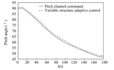
4 Simulated Analysis On the basis of the full model of attitude dynamics, simulation verification is made in accordance with the above analysis. The model reference variable structure control law of the pitch channel adopts Eq. (36), the adaptive control law adopts Eq.(37), the model reference variable structure control law of the yaw channel adopts Eq.(41), and the adaptive control law adopts Eq. (42). In addition, the model reference variable structure control law of the roll channel adopts Eq. (50), and the adaptive control law adopts Eq. (51). This paper compares the control effect of the traditional PID control with the sliding mode variable structure adaptive control based on the model reference, and guarantees that the deflection angle of rocket motor is within the range of±3°. Meanwhile, it also guarantees that the change scopes of the deflection angle by the two control methods of each channel are approximately equal to each other. Based on this premise, the variable structure and adaptive control coefficient shall take values from Tables. 1-4. The simulation results are shown in Figs. 1-11. The four solid boosters will be separated within the range of 114.9-121.6 s.
表 1

Table 1 Sliding mode surface coefficient pi
| Flight time t(s) |
Pitch channel (i=0) |
Yaw channel (i=1) |
Roll channel (i=2) |
| t≤10 s |
1.2 |
2.0 |
9.0 |
| 10 s < t ≤ 110 s |
1.3 |
1.2 |
8.0 |
| 110 s < t ≤ 130 s |
1.4 |
1.3 |
2.2 |
| 130 s < t ≤ 180 s |
1.5 |
1.5 |
2.0 |
|
Table 1 Sliding mode surface coefficient pi
|
表 2

Table 2 Saturation characteristic coefficient σi
| Pitch channel (i=0) |
Yaw channel (i=1) |
Roll channel (i=2) |
| 2 |
1.6 |
2.5 |
|
Table 2 Saturation characteristic coefficient σi
|
表 3

Table 3 Adaptive coefficient ai
| Flight time t(s) |
Pitch channel (i=0) |
Yaw channel (i=1) |
Roll channel (i=2) |
| t≤10 s |
3 |
4 |
12.0 |
| 10 s < t ≤ 70 s |
7 |
3 |
10.0 |
| 70 s < t ≤ 110 s |
7 |
6 |
10.0 |
| 110 s < t ≤ 130 s |
5 |
5 |
8.0 |
| 130 s < t ≤ 180 s |
7 |
6 |
7.5 |
|
Table 3 Adaptive coefficient ai
|
表 4

Table 4 Coefficient of exponential approach law ki
| Flight time t(s) |
Pitch channel (i=0) |
Yaw channel (i=1) |
Roll channel (i=2) |
| t≤10 s |
1.2 |
0.9 |
3.3 |
| 10 s < t ≤ 70 s |
1.4 |
1.1 |
3.3 |
| 70 s < t ≤ 110 s |
1.4 |
1.3 |
3.3 |
| 110 s < t ≤ 130 s |
1.5 |
1.4 |
9.0 |
| 130 s < t ≤ 170 s |
1.6 |
2.1 |
10.5 |
| 170 s < t ≤ 180 s |
1.7 |
2.1 |
12 |
|
Table 4 Coefficient of exponential approach law ki
|
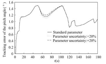
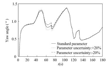
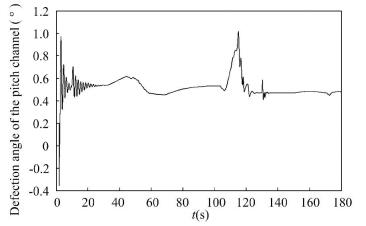
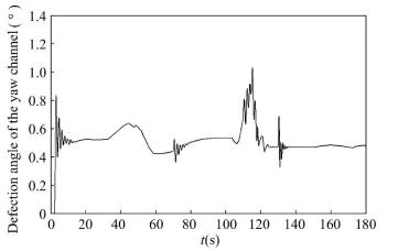
It can be seen from the simulation results that, after adopting the adaptive control of sliding mode variable structure based on the model reference, the attitude angle of the pitch and yaw channels are stable. Meanwhile, this control method can suppress the external disturbance and implement online adaptive compensation to the aerodynamic parameter uncertainty of the pitch and yaw channels. Tracking error of the pitch angle is within 1.5° and tracking error of the yaw angle is within 1.3°. In the 50 s-70 s phase, the rocket is passing through the strong wind area where the wind disturbance is obviously increased and the yaw angle curve undergoes large fluctuation, as shown in Fig. 3. However, the attitude angle curve has only small amplitude of fluctuation that means the adaptive method of the variable structure can effectively suppress the wind disturbance and parameter perturbation. During period from 70 s to 110 s, the reason why attitude angle curves of two channels suffer a large fluctuate is disturbance torque which ascends from 70 s to 103, peaks at 103 s and then declines dramatically during 103 s to 110 s. In Figs. 5 and 6, the defection angle of pitch channel is within 0.8° and the defection angle of yaw channel is less than 0.7°. Due to the transformation of control law, small fluctuations of defection angle of pitch channel can be seen at 10 s, 110 s, 130 s and 170 s and small fluctuations of defection angle of yaw channel can be seen at 10 s, 70 s, 110 s and 130 s. As shown in Figs. 5 and 6, the reason of curve mutation near 120 s is the separation of the four solid boosters and the rocket attitude suffers large disturbance, especially including disturbance caused by asynchronism of thrust, so that the attitude angle curve has a large fluctuation, while the attitude stabilization has been achieved.
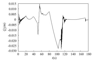
The disturbance to the roll channel mainly originates from the parameter uncertainty, external disturbance and control effect of the pitch and yaw channels on the roll channel. The tracking error of roll angle when adopting the variable structure adaptive method is within 3.8° and defection angle of roll channel is less than 3° that meet technical requirements. Same as pitch and yaw channel, altering control coefficients leads to little fluctuations of defection angle at 10 s, 110 s, 130 s and 170 s while the impact on attitude angle has been small. In the 120 s phase, this control method can more effectively suppress the disturbance resulting from the solid boosting separation and restrain large variations of parameters. Particularly disturbance torque of asychronism of thrust and thrust deflexion is large.
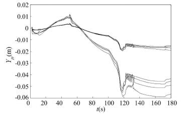
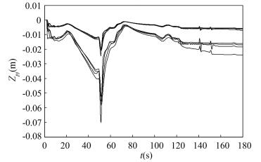
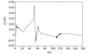
In Figs. 8 and 9, liquid sloshing amplitude of Zp and Yp propellant containers can remain stable after taking off and suffering disturbances. Meanwhile, amplitudes are small enough to meet the technical requirements. First and second order elastic vibration have the most energy and greatest impacts on rocket. Therefore, this article focuses on the main point. As shown in Figs. 10 and 11, the generalized displacement of first and second order elastic vibration can maintain stability during the entire flight procedure.
According to the above analysis, simulation results indicate that the method adopted in this paper has a high anti-interference ability which means that the control system has a strong robustness with respect to system uncertainties and disturbance. In the meantime, its characteristics such as small tracking errors of attitude angles, excellent control quality and high reliability have been demonstrated in the simulations.
Meanwhile the parameter uncertainty can be seen from Figs. 2-4 including aerodynamic parameter uncertainty and control parameter uncertainty has a certain impact on the control effect of three channels, but it will not affect the attitude stability of the rocket body. In three channels, there is no great difference between the curve of standard parameter and parameter uncertainty form 40 s to 100 s phase and the reason is that the aerodynamic parameter greatly changes in the strong wind phase. In the phase, the rocket body is more sensitive to the changes of the parameters, and the impact of parameter uncertainty on the dynamic performance of the rocket body is also increased. In Fig. 4, the impact of parameter uncertainty increases greatly after separation of four solid boosters while it will not affect the attitude stability and the tracking error of roll angle is within the margin of technical requirements. It can be seen from the simulation results that the sliding mode variable structure adaptive control method based on the model reference does not depend on the accurate model of the controlled object, and can perform real-time adjustment on the control coefficient to make the system operate at the near-optimum state, so as to solve the problem of parameter uncertainty.
5 Conclusions In view of the multiple structure disturbances, external disturbances, parameter uncertainties of the solid strap-on rocket, unmodeled dynamics and coupling between channels of the system, and on the basis of the deviator model of attitude dynamics, this paper adopts the variable structure adaptive control method which will have a strong adaptability and robustness on all disturbances and uncertainties. In the meanwhile, this paper uses the Lyapunov function to prove the system asymptotic stability. Through the theoretical analysis and numerical simulation, the variable structure adaptive control law designed in this paper can effectively overcome the impact of the disturbances, parameter uncertainties, coupling of the system and guarantee the attitude stability of the rocket in flight phase.


 0)
0)
 0)
0)
 0)
0)
 0)
0)
 0)
0)
 0)
0)
 0)
0)
 0)
0)
 0)
0)
 0)
0)
 0)
0)
 0)
0)
 0)
0)
 0)
0)
 0)
0)
 0)
0)
 0)
0)
 0)
0)
 0)
0)
 0)
0)
 0)
0)
 2017, Vol. 24


