In recent years, with the development of computer simulation technology, virtual test technology has developed rapidly owing to its high efficiency and low cost, which can save manpower and material resources. Virtual test often involves the calculation of electromagnetic wave propagation for applications such as virtual radar testing and virtual radar guided missile testing. However, in many existing simulation systems, the calculation of electromagnetic wave propagation is embedded within the simulation model, and is therefore not independent, not easily configured, and not easily reused[1-2]. For example, the advanced propagation model[3] used to solve the problem of electromagnetic wave propagation in a complex environment can only calculate the work scope of the radar, and cannot track the target. Therefore it is not independent and is unable to be reused[4]. As another example, the least squares method for calculation of atmospheric absorption loss, which computes the attenuation values of electromagnetic wave propagation, can only be used in a specified direction and for a specified antenna height, which is not easily applied in a virtual test system[5]. The propagation model of electromagnetic wave has been researched for many years, and the examples are shown as follows: in Ref.[6] the propagation model had been researched in radar guidance missile system; Baker[7] proposed a virtual simulation support architecture-JMASS, which can support the "project-level" and "operational-level" construction of radio propagation model, the advanced propagation model (APM) is a very famous electromagnetic propagation model, which has been widely used in many fields. However, these models can not be directly used in virtual test, and calculate the electromagnetic attenuation ratio in real time.
In this paper, we concentrate the electromagnetic propagation model which can be used in virtual test. The virtual test platform denoted as the Harbin Institute of Technology test and training enabling architecture (HIT-TENA) incorporated the technology of advanced universal testing software denoted as high level architecture (HLA) and simulation technology, and meets the requirements for the testing of large-scale virtual events[8]. The test platform was designed on the basis of the test and training enabling architecture (TENA) developed by the U.S. Department of Defense, and HIT-TENA employs a similar open architecture[9]. The present study develops an electromagnetic wave propagation component for achieving the flexible support of electromagnetic wave propagation testing using the HIT-TENA platform by making the test resources interoperable, reusable, and capable of being applied in combination. The proposed approach supports the calculation of propagation attenuation in a variety of tests, which is affected by various environmental factors in space. Additionally, the greatest advantage of the proposed component is that it provides for real-time computing. The propagation algorithm is implemented in C language, and the calculation speed of the algorithm is much faster than the standard tool—MATLAB; thus, the component meets the real-time requirements of virtual test systems.
1 Modeling of Electromagnetic Wave PropagationDifferent weather conditions, such as clear weather, foggy, rainy, and snowy, have varying effects on the propagation of electromagnetic waves. The electromagnetic wave propagation component can obtain different propagation attenuation values depending upon the selected environmental conditions of the virtual test by employing different mathematical propagation models[10-11].
1.1 Clear Weather Propagation ModelElectromagnetic wave propagation loss under clear weather conditions is mainly due to absorption by water vapor and oxygen in the lower troposphere. The densities of water vapor and oxygen, however, are not homogeneous, and decrease progressively as altitude increases[12]. In addition, the temperature of the atmosphere decreases as altitude increases, so calculations of electromagnetic wave propagation require temperature correction.
The calculation of atmospheric absorption loss mainly comprises the followings. The attenuation rates of oxygen γo and the attenuation rates of oxygen of water vapor γw are given in units of dB/km in terms of the surface water vapor density ρ (annual average; g/m3) as follows.
| $\begin{array}{l} {\gamma _{\rm{o}}} = \left\{ \begin{array}{l} \left[ {7.19 \times {{10}^{ - 3}} + \frac{{6.09}}{{{f^3} + 0.227}} + \frac{{4.81}}{{{{\left( {f - 57} \right)}^2} + 1.5}}} \right]{f^2} \times {10^{ - 3}},f < 57{\rm{GHz}}\\ \left[ {3.79 \times {{10}^{ - 3}}f + \frac{{0.265}}{{{{\left( {f - 63} \right)}^2} + 1.59}} + } \right.\\ \;\;\;\;\;\;\;\;\;\left. {\frac{{0.028}}{{{{\left( {f - 118} \right)}^2} + 1.47}}} \right]{\left( {f + 198} \right)^2} \times {10^{ - 3}},\;\;\;\;\;\;\;\;\;\;\;\;\;\;63{\rm{GHz}} < f < 350{\rm{GHz}} \end{array} \right.\\ {\gamma _{\rm{w}}} = \left[ {0.050 + 0.0021\rho + \frac{{3.6}}{{{{\left( {f - 22.2} \right)}^2} + 8.5}} + \frac{{10.6}}{{{{\left( {f - 183.3} \right)}^2} + 9.0}} + \frac{{8.9}}{{{{\left( {f - 325.4} \right)}^2} + 26.3}}} \right] \times \\ \;\;\;\;\;\;\;\;\rho f \times {10^{ - 4}},f < 350{\rm{GHz}} \end{array}$ |
The temperature corrections for the attenuation rates of oxygen and water vapor are given in terms of the surface air temperature (annual average; ℃) as follows.
| $\begin{array}{*{20}{c}} {\Delta {\gamma _{\rm{o}}} = {\gamma _{\rm{o}}}\left( {15 - t} \right)/100\;\;\;\;\left( {{\rm{dB/km}}} \right)}\\ {\Delta {\gamma _{\rm{w}}} = {\gamma _{\rm{w}}}\left( {15 - t} \right) \times 0.006\;\;\;\;\left( {{\rm{dB/km}}} \right)} \end{array}$ |
The effective heights of oxygen and water vapor are given in units of km as follows.
| $\begin{array}{l} {h_{\rm{o}}} = \left\{ \begin{array}{l} 6,\;\;\;\;\;\;\;\;\;\;\;\;\;\;\;\;\;\;\;\;\;f < 63{\rm{GHz}}\\ 6 + \frac{{40}}{{{{\left( {f - 118.7} \right)}^2} + 1}},63{\rm{GHz}} < f < 350{\rm{GHz}} \end{array} \right.\\ {h_{\rm{w}}} = {h_{{\rm{wo}}}}\left[ {1 + \frac{3}{{{{\left( {f - 22.2} \right)}^2} + 5}} + \frac{5}{{{{\left( {f - 183.3} \right)}^2} + 6}} + } \right.\\ \;\;\;\;\;\;\;\left. {\frac{{2.5}}{{{{\left( {f - 325.4} \right)}^2} + 4}}} \right],f < 350{\rm{GHz}}\\ {h_{{\rm{wo}}}} = \left\{ \begin{array}{l} 1.6,\;{\rm{Clear}}\;{\rm{weather}}\\ 2.1,{\rm{Cloudy}} \end{array} \right. \end{array}$ |
The temperature correction factors for the equivalent path lengths of oxygen and water vapor at low altitude are given in units of km with respect to the equivalent earth radius re (km), the annual average equivalent earth radius factor k, the altitude of the earth surface hs (km), and the propagation path elevation angle θ (°) as follows.
| $\begin{array}{*{20}{c}} {{r_{\rm{e}}} = 6370 \times k\;\;\;\;\left( {{\rm{km}}} \right)}\\ {y = \sqrt {{{\sin }^2}\theta + 2{h_{\rm{s}}}/{r_{\rm{e}}}} }\\ {g\left( {{h_{\rm{o}}}} \right) = 0.661y + 0.339\sqrt {{y^2} + 5.5{h_{\rm{o}}}/{r_{\rm{e}}}} }\\ {g\left( {{h_{\rm{w}}}} \right) = 0.661y + 0.339\sqrt {{y^2} + 5.5{h_{\rm{w}}}/{r_{\rm{e}}}} } \end{array}$ |
The total attenuation of oxygen and water vapor absorption collectively in dB is given as follows.
| ${L_{\rm{a}}} = \left\{ \begin{array}{l} \frac{{\left( {{\gamma _{\rm{o}}} + \Delta {\gamma _{\rm{o}}}} \right){h_{\rm{o}}}\exp \left( { - {h_{\rm{s}}}/{r_{\rm{o}}}} \right) + \left( {{\gamma _{\rm{w}}} + \Delta {\gamma _{\rm{w}}}} \right){h_{\rm{w}}}}}{{\sin \theta }},\theta > {10^ \circ }\\ \frac{{\left( {{\gamma _{\rm{o}}} + \Delta {\gamma _{\rm{o}}}} \right){h_{\rm{o}}}\exp \left( { - {h_{\rm{s}}}/{h_{\rm{o}}}} \right)}}{{g\left( {{h_{\rm{o}}}} \right)}} + \frac{{\left( {{\gamma _{\rm{w}}} + \Delta {\gamma _{\rm{w}}}} \right){h_{\rm{w}}}}}{{g\left( {{h_{\rm{w}}}} \right)}},\theta > {10^ \circ } \end{array} \right.$ | (1) |
The algorithm is described as follows.
Step 1 To get the frequency of electromagnetic wave, calculate the decay rate of oxygen γo and water vapor γw;
Step 2 To calculate the effective height of the oxygen ho and water vapor hw, according to their temperature correction;
Step 3 To calculate the equivalent path correction factor of oxygen g(ho) and water vapor g(hw), according to the radius of the earth;
Step 4 To calculate the electromagnetic wave propagation attenuation, according to the general formula (1) of oxygen and water vapor absorption.
1.2 Foggy Propagation ModelThe scattering of electromagnetic waves through the water droplets of which fog is composed submit to Rayleigh scattering theory. When the frequency is below 200 GHz, the attenuation rate γw of electromagnetic waves is proportional to the moisture content per unit volume (i.e., the liquid water density ρ)[13-15] as follows:
| ${\gamma _{\rm{w}}} = \kappa \rho \left( {{\rm{dB/km}}} \right)$ |
where κ is the fog attenuation coefficient (dB/km)/(g/m3). The expression is suitable for frequencies up to of 1000 GHz.
The value of κ can be computed for f (GHz) from the following.
| $\kappa = \frac{{0.819f}}{{\varepsilon ''\left( {1 + {\eta ^2}} \right)}}\left( {\left( {{\rm{dB/km}}} \right)/\left( {{\rm{g}}/{m^3}} \right)} \right)$ | (2) |
| $\eta = \frac{{2 + \varepsilon '}}{{\varepsilon ''}}$ | (3) |
Here, ε′ and ε″ are respectively the real and imaginary components of the complex dielectric constant of water given as
| $\varepsilon ' = \frac{{{\varepsilon _0} - {\varepsilon _1}}}{{1 + {{\left( {f/{f_p}} \right)}^2}}} + \frac{{{\varepsilon _1} - {\varepsilon _2}}}{{1 + {{\left( {f/{f_s}} \right)}^2}}} + {\varepsilon _2}$ | (4) |
| $\varepsilon '' = \frac{{f\left( {{\varepsilon _0} - {\varepsilon _1}} \right)}}{{{f_p}\left[ {{{\left( {f/{f_p}} \right)}^2}} \right]}} + \frac{{f\left( {{\varepsilon _1} - {\varepsilon _2}} \right)}}{{{f_s}\left[ {{{\left( {f/{f_s}} \right)}^2}} \right]}}$ | (5) |
where
| $\begin{array}{*{20}{c}} {{\varepsilon _0} = 77.6 + 103.3\left( {\frac{{300}}{T} - 1} \right)}\\ {{\varepsilon _1} = 5.48}\\ {{\varepsilon _2} = 3.51}\\ {{f_{\rm{p}}} = 20.09 - 142 \times \left( {\frac{{300}}{T} - 1} \right) + 294 \times {{\left( {\frac{{300}}{T} - 1} \right)}^2}}\\ {{f_{\rm{s}}} = 590 - 1500 \times \left( {\frac{{300}}{T} - 1} \right)} \end{array}$ |
The related parameters are the absolute temperature T (K), the primary relaxation frequency fp (GHz), and the secondary relaxation frequency fs (GHz).
The attenuation Lw of electromagnetic wave propagation in fog can be expressed as
| ${L_{\rm{w}}} = {d_{\rm{e}}}{\gamma _{\rm{w}}} = {d_{\rm{e}}}\kappa \rho $ |
where de is the actual path length (km).
For an earth-to-air sloping path, if the height of the clouds and fog is Δh, then
| ${d_{\rm{e}}} = \frac{{\Delta h}}{{\sin \theta }}$ |
The algorithm is described as follows.
Step 1 To get the frequency of electromagnetic wave and calculate the dielectric constant of water according to Eqs. (4) and (5);
Step 2 To calculate the attenuation coefficient κ of fog according to Eq. (2);
Step 3 To calculate the actual path length de of the electromagnetic wave propagation and the electromagnetic wave attenuation coefficient γw;
Step 4 To calculate the electromagnetic wave propagation attenuation Lw=deγw.
1.3 Rainy Propagation ModelPrecipitation, including rainfall, snowfall, and hail, increase the propagation loss of electromagnetic waves. Of the three, rainfall causes the most serious attenuation[16-17].
The rainy attenuation rate γα is given as
| ${\gamma _{\rm{\alpha }}} = \kappa {R^{^{\rm{\alpha }}}}$ | (6) |
where R is the rainy intensity (mm/h); κ and α are parameters related to the frequency, the polarization angles, and the elevation of the path. In a more accurate calculation, κ and α are respectively
| $\kappa = \frac{{{\kappa _{\rm{H}}} + {\kappa _{\rm{\gamma }}} + \left( {{\kappa _{\rm{H}}} - {\kappa _{\rm{\gamma }}}} \right){{\cos }^2}\theta \cos 2\tau }}{2}$ | (7) |
| $\alpha = \frac{{{\kappa _{\rm{H}}}{\alpha _{\rm{H}}} + {\kappa _{\rm{\gamma }}}{\alpha _{\rm{\gamma }}} + \left( {{\kappa _{\rm{H}}}{\alpha _{\rm{H}}} - {\kappa _{\rm{\gamma }}}{\alpha _{\rm{\gamma }}}} \right){{\cos }^2}\theta \cos 2\tau }}{{2\kappa }}$ | (8) |
where τ is the polarization elevation given as τ = 0 for horizontal polarization, τ=90° for vertical polarization, and τ=45° for circular polarization, and κH, κγ, αH, αγ are regression coefficients. When the rainy intensity distribution along the propagation path is known, the rainy attenuation is given as
| ${A_{\rm{R}}} = \sum\limits_{i = 1}^n {{\gamma _{{\rm{Ri}}}}{L_{\rm{i}}}} $ | (9) |
Here, we assume that the rainfall along the propagation path can be divided into n segments, where, for the i-th segment, the path length is Li, the rainy intensity is Ri, and the related rainy attenuation rate is γRi.
The algorithm is described as follows.
Step 1 To obtain f and the positions of the source and target, then calculate κ and α related to the rainy attenuation rate.
Step 2 To calculate γR of the known rainy intensity by the obtained parameters (with temperature correction).
Step 3 To divide the rainfall along the propagation path into n segments, and establish Li, Ri, and the rainy attenuation rate rRi. (To meet the requirements of real-time calculations, we simplify Eqs.(6)-(9), which is difficult to realize in the C language, and results in a running time that exceeds the requirements).
Step 4 To calculate AR, according to Ri along the electromagnetic wave propagation path.
1.4 Snowy Propagation ModelThe attenuation caused by snowfall and hail (ice), is different from that of rain. According to Barton[18]: "The most noteworthy difference between the properties of water in liquid and solid form is the smallness of the attenuation in the latter case." Also, with reference to electromagnetic waves at 30 GHz and, hence, presumably at all lower frequencies[18]"… it seems safe to say that the attenuation by ice crystals can almost always be neglected". The following equation for the attenuation of snowfall given by Gunn and East tends to support these statements[18].
| $A = \frac{{0.00349{\gamma ^{1.6}}}}{\lambda } + \frac{{0.0022\gamma }}{\lambda }\left( {\frac{{{\rm{dB}}}}{{{\rm{km}}}}} \right)$ |
Here, γ is the snowy rate in equivalent liquid water content and λ is given in cm. The majority of writing on the subject appears to concur that attenuation by snowfall and hail is minor. For example, Hogg and Chu[19] state, "… ice and dry snow exhibit very low loss in the microwave band." However, wet-snow attenuation can apparently be very large, and even larger than that for equivalent rainfall. For example, Bell reported a one-way loss of 25 dB at 11 GHz for a 55-km path with 2 mm/h of wet snow.
The algorithm is described as follows.
Step 1 To obtain f and the positions of source and target, calculate κ and α related to the snowy attenuation rate.
Step 2 To calculate γR for a known snowy intensity by the obtained parameters (with temperature correction).
Step 3 To obtain λ, and calculate γ.
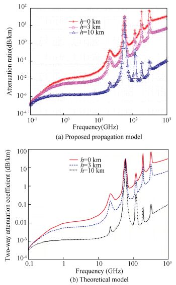
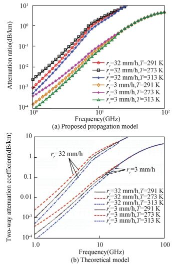
1.5 Verification of Propagation ModelsThe propagation models for the weather conditions considered can be invoked within simulations to compute electromagnetic wave propagation attenuation to verify the correctness of the models. In this paper, the calculations of electromagnetic wave propagation under clear weather, rainy, and snowy conditions were verified by comparison with theoretical values, which can get from Refs.[20] and [21]. In these verification tests, the parameters of our model are set by referring to these preferences.
The attenuation model test results for clear weather conditions and the corresponding theoretical values are shown in Fig. 1, where the horizontal axis represents the frequency of electromagnetic wave, and the vertical axis represents the attenuation ratio. Fig. 1(a) shows computation results of our proposed propagation model, and Fig. 1(b) shows the theoretical model. As shown in the figures, the attenuation ratios in proposed model and theoretical model have very similar variational tendency, it is most probable the attenuation ratio increases as the frequency of electromagnetic wave increases, but at some frequencies, such as 50 GHz, 200 GHz, the attenuation ratio has local peak. Moreover, along with the altitude increases, the attenuation ratio would like decrease correspondingly. This is because that the density of oxygen and water vapor decrease with the increasing altitude, as a result, attenuation rate of electromagnetic wave decreases.
|
Figure 1 Verification of the clear weather propagation model |
The rainy propagation model test results and theoretical values without temperature correction are shown in Fig. 2. Fig. 2(a) shows computation results of our proposed rainy propagation model, and Fig. 2(b) shows the theoretical model. As shown in the figures, the attenuation ratios in proposed model and theoretical model have very similar variational tendency, which is that with the rainy intensity increasing, the attenuation ratio of electromagnetic waves are observed to significantly increase. Meanwhile, when the rainy intensity remains invariantly, the attenuation ratio will decrease as temperature rise. However, the temperature can be ignored when the frequency exceeds 20 GHz.
|
Figure 2 Verification of the rainy propagation model |
The snowy attenuation model test results and theoretical values without temperature correction are shown in Fig. 3. Fig. 3(a) shows computation results of our proposed snowy propagation model, and Fig. 3(b) shows theoretical model. As shown in the figures, the attenuation ratio in proposed model and theoretical model have very similar variational tendency, which is that with the snowy heavily decreasing, the attenuation ratio of electromagnetic waves are observed to significantly decrease. Meanwhile, at the same snowy heavily, the attenuation ratio will decrease with the increasing temperature. However, the temperature can be ignored when the frequency exceeds 40 GHz.

|
Figure 3 Verification of the snowy propagation model |
In the verification experiments, clear weather, rainy, and snowy conditions were tested, and were found to be equivalent to the theoretical values, which verifies the reliability of the propagation models employed in the electromagnetic wave propagation component.
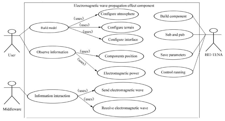
2 Design of the Electromagnetic Wave Propagation ComponentThe main function of the electromagnetic propagation component is calculating the propagation attenuation under different weather conditions in virtual testing. The main functions in detail are as follows.
(1) Configuring atmospheric parameters, such as the atmospheric attenuation coefficient and the density of water vapor, and topographic parameters such as the sea environment and land environment.
(2) Accepting the electromagnetic wave from source emitting and target reflection, and calculating the propagation attenuation.
(3) Configuring a number of other components in the system, and realization of multi-threaded operation and multiple target tracking.
(4) Display and update source, electromagnetic wave, and target information in real time.
The electromagnetic propagation component use-case analysis is shown in Fig. 4.
|
Figure 4 The use-case diagram of the electromagnetic wave propagation component |
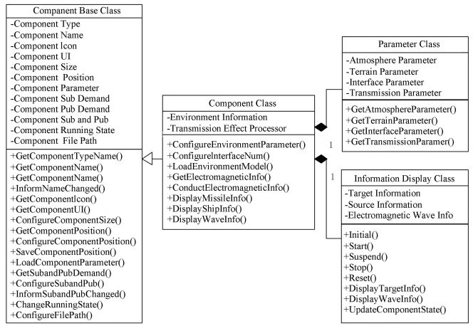
The electromagnetic propagation component design class diagram is shown in Fig. 5. The component base class is a specific class of platform that forms the basis of component design in the platform, establishes the component framework, and functions as a bridge of communication between the component and platform. The electromagnetic wave propagation class inherits from the component base class, and enriches the component functions, including the loading of various environmental information and the computing of propagation attenuation. The parameter configuration class includes the configuration of various parameters required by the component. The information display class obtains all information to be observed by the user regarding the source, the electromagnetic wave, and the target.
|
Figure 5 The class design diagram of the electromagnetic propagation component |
3 Application in Missile Virtual Testing
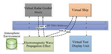
To conduct a comprehensive verification of the electromagnetic wave propagation component and the propagation models used therein, we constructed a virtual test system for radar guided missiles[22]. The system is comprised of a virtual missile component, the electromagnetic wave propagation component, and a virtual ship component. The information interaction relations for each component of the system are shown in Fig. 6.
|
Figure 6 Information interaction relations for each component of the virtual test system for radar guided missiles |
The virtual radar carried by the virtual missile component transmits electromagnetic waves to the virtual ship component through the electromagnetic wave propagation component, in which the propagation attenuation of the electromagnetic wave is calculated. The virtual ship component reflects the electromagnetic wave according to its radar cross-section (RCS) to the virtual radar through the electromagnetic wave propagation component, in which the propagation attenuation of the electromagnetic wave is again calculated. The virtual radar obtains the position of the virtual ship component by computing and analyzing the information obtained from the electromagnetic wave.
The system can compute more than a single task simultaneously. Therefore, the system can include more than a single virtual missile component and a single virtual ship component, the numbers of which are configured by the user.
The system simulation test builds a new test project in the experimental platform, adds the virtual missile component, virtual ship component, and the electromagnetic wave propagation component to the project, and configures the relationship between the Subscriber and Publisher. For the virtual test system discussed in this paper, we selected the North-East coordinate system, where the coordinate origin was the missile launching point, and the unit of each axis was kilometers. The initial position of the virtual ship was (40, 40, 0), its speed was 50 m/s, and its direction was 45° east of south. The initial speed of the virtual missile was 300 m/s, the emission direction was 15 ° east of north, the radar transmitter power was 70 dB, and the receiver sensitivity was-70 dB.
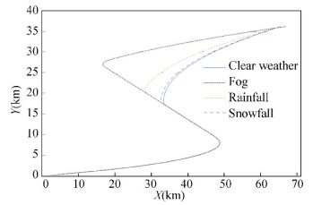
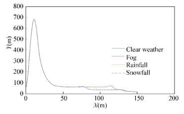
3.1 Test Under Various WeatherFirstly, we tested the influence of various weather conditions on the missile trajectory and altitude. The water vapor density of fog was 3 g/m3, and the rainy intensity was 3 mm/h, and the snowy intensity was 16 mm/h, while all other parameters employed were typical values for the various weather conditions considered. The capture time (CT) and capture distance (CD) obtained under a given weather conditions (WC) are listed in Table 1, where the capture time is the missile flight time at the point where the missile status is transferred from searching to tracking, and the capture distance is the distance between the missile and the target at that point in time. From Figs. 7 and 8, we observe that the influence on the missile trajectory and altitude owing to electromagnetic wave propagation attenuation becomes increasingly significant in the order of clear weather, snowy, foggy, and rainy conditions. Clearly, the influence of the environment on electromagnetic wave propagation attenuation affects the capture time and capture distance, as well as the missile trajectory and altitude.
| Table 1 The capture time (CT) and capture distance (CD) under various weather conditions (WC) |
|
Figure 7 Missile trajectory under various weather conditions |
|
Figure 8 Missile altitude under various weather conditions |
3.2 Test Under Foggy Weather
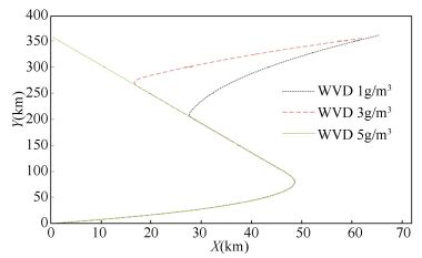
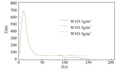
We further tested the influence of foggy conditions with changing water vapor density (WVD) on CT and CD, and the results are listed in Table 2. As shown in Figs. 9 and 10, the missile trajectory and altitude are heavily influenced by foggy conditions with various WVD. Under foggy conditions with a WVD up to 5 g/m3, the missile borne radar is unable to capture the target, therefore, the missile is unable to obtain an appropriate trajectory because of the excessive electromagnetic wave propagation attenuation.
| Table 2 The capture time (CT) and capture distance (CD) under foggy weather with changing water vapor density (WVD) |
|
Figure 9 Missile trajectory under foggy weather with changing water vapor density (WVD) |
|
Figure 10 Missile altitude under foggy weather with changing water vapor density (WVD) |
3.3 Test Under Rainy Weather
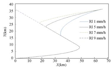
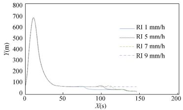
We considered the influence of rainy conditions with changing rainy intensity (RI) on CT and CD, and the results are listed in Table 3. As shown in Figs. 11 and 12, the missile trajectory is also heavily influenced by rainy conditions. Under rainy conditions with an RI up to 9 mm/h, the missile borne radar is unable to capture the target, and, therefore, the missile is unable to obtain an appropriate trajectory.
| Table 3 The capture time (CT) and capture distance (CD) under rainy weather with changing rainy intensity (RI) |
|
Figure 11 Missile trajectory under rainy weather with changing rainy intensity (RI) |
|
Figure 12 Missile altitude under rainy weather with changing rainy intensity (RI) |
3.4 Test Under Snowy Weather
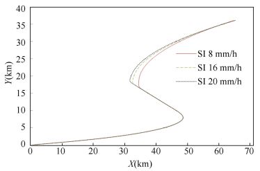
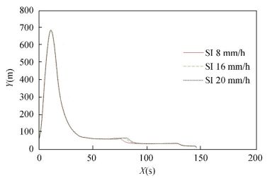
We considered the influence of snowy conditions with changing snowy intensity (SI) on CT and CD, and the results are listed in Table 4. As shown in Figs. 13 and 14, the missile trajectory is only slightly influenced by the snowy conditions considered. The missile more readily captures the target under snowy conditions compared with foggy and rainy conditions.
| Table 4 The capture time (CT) and capture distance (CD) under snowy condition with changing snowy intensity (SI) |
|
Figure 13 Missile trajectory under snowy condition with changing snowy intensity (SI) |
|
Figure 14 Missile altitude under snowy condition with changing snowy intensity (SI) |
According to the system tests conducted, the electromagnetic wave propagation component effectively calculates the electromagnetic propagation attenuation under various weather conditions, and the test values obtained are in accordance with theoretical values[3, 21]. Moreover, the component can be directly implemented as an independent component interacting with other components in the HIT-TENA platform.
4 ConclusionsIn this paper, we focused on the modeling of electromagnetic wave propagation under clear weather, foggy, rainy, and snowy conditions. Then we developed an electromagnetic wave propagation component running on the HIT-TENA platform to support virtual test. This component not only can effectively calculate the electromagnetic propagation attenuation under different weather conditions, but also can be freely and repeatedly combined with other components in the HIT-TENA platform. The component enriches the HIT-TENA platform by supporting an enhanced simulation capacity and improved test efficiency. In the virtual test environment, the user can select different weather conditions and freely and easily configure the environmental weather parameters, which maximizes user control and ensures test precision and fidelity.
| [1] |
Su Y. Modeling and simulation for multipath transmitting of RF signal in a complex terrain.
Ship Electronic Engineering, 2009, 29(1): 168-172.
( 0) 0)
|
| [2] |
Min T, Yang J H, Dun L I, et al. Study on the simulation system of virtual battlefield in electromagnetic environment.
Command Control & Simulation, 2007, 29(2): 83-91.
( 0) 0)
|
| [3] |
Barrios A E, Anderson K, Lindem G. Low altitude propagation effects-A validation study of the advanced propagation model (APM) for mobile radio applications.
IEEE Transactions on Antennas & Propagation, 2006, 54(10): 2869-2877.
DOI:10.1109/TAP.2006.882163 ( 0) 0)
|
| [4] |
Zhang J Z, Yuan X J, Zhao X J, et al. 3D visualization of Radar detection range based on advanced propagation model.
Computer Engineering, 2012, 38(4): 281-283.
( 0) 0)
|
| [5] |
Liu W D, Wu Shunjun. An LSE algorithm for troposphere absorption loss.
Jounal of Xidian University, 2000, 27(3): 290-293.
( 0) 0)
|
| [6] |
Department of Defense Interface Standard: Electromagnetic Environmental Effects Requirements for Systems. MIL-STD-464A. Department of Defense, 2002.
( 0) 0)
|
| [7] |
Baker A M A, Alam M S, Tanrioven M, et al. Electromagnetic compatibility analysis in buildings affected by lightning strike.
Electric Power Systems Research, 2005, 73(2): 197-204.
DOI:10.1016/j.epsr.2004.08.004 ( 0) 0)
|
| [8] |
Zhang Minli. Research on Technologies of Object Modeling in Infrastructure for Virtual Test System.
Harbin: Harbin Institute of Technology, 2009: 4-45.
( 0) 0)
|
| [9] |
Wang Xuesong, Xiao Shunping, Feng Dejun.
Modern Radar Electronic Warfare System Modeling and Simulation. Beijing: Publishing House of Electronics Industry, 2010.
( 0) 0)
|
| [10] |
Guo Gang, Li Ge. Synthetic environment data representation and interchange specification overview.
Intelligence Conduct Control System and Simulation Technology, 2001(02): 52.
( 0) 0)
|
| [11] |
Wang Guoyu, Wang Liandong.
Radar Electronic Warfare System Mathematical Simulation and Evaluation. Beijing: National Defense Industry Press, 2004.
( 0) 0)
|
| [12] |
Meng J, Wang L D, Wang G L, et al. Electromagnetic environment simulation for Radar EW system.
Computer Simulation, 2004, 21(12): 21-24.
( 0) 0)
|
| [13] |
Xie Yixi.
The Principle and Application of Radio Wave Propagation. Beijing: People Post Press, 2008.
( 0) 0)
|
| [14] |
Zhao J, Zhang Z, Shuai L I. Study of Electromagnetic Environment Simulation for Radar.
Shipboard Electronic Countermeasure, 2009.
( 0) 0)
|
| [15] |
IEEE. IEEE 1516-2010: IEEE Standard for Modeling and Simulation (M & S) High Level Architecture (HLA)-Framework and Rules. Piscataway: IEEE, 2010.
( 0) 0)
|
| [16] |
Hu Huibin, Ma Junjie. Study on the Algorithms of Predicting the Radio Propagation Characteristics in Complex Environments.
Changsha:National University of Defense Technology, 2006: 4-36.
( 0) 0)
|
| [17] |
Jiao Peinan, Zhang Zhongzhi.
Radar Environment and Wave Propagation. Beijing: Publishing House of Electronics Industry, 2007.
( 0) 0)
|
| [18] |
Barton D K.
Radar System Analysis and Modeling. Beijing: Publishing House of Electronics Industry, 2012.
( 0) 0)
|
| [19] |
Hogg D C, Chu T S. The role of rain in satellite communications.
Proceedings of IEEE, 1975, 63(9): 1308-1331.
DOI:10.1109/PROC.1975.9940 ( 0) 0)
|
| [20] |
Zhang Yu.
Space Transmission of Electromagnetic Wave. XI'an: Xi'an Electronic Science and Technology University Press, 2007.
( 0) 0)
|
| [21] |
Xie Yixi.
Radio Wave Propagation: Principles and Applications. Beijing: Posts and Telecommunications Press, 2008.
( 0) 0)
|
| [22] |
Wu Yingnian, Zhang L, Zhang L F, et al. Survey on electromagnetic environment simulation and visualization.
Journal of System Simulation, 2009, 21(20): 6332-6338.
DOI:10.16182/j.cnki.joss.2009.20.057 ( 0) 0)
|
 2017, Vol. 24


