2. University of Chinese Academy of Sciences, Beijing 100049, China
Offner form [1-2] and Dyson form [3-4] are the two typical concentric configurations. Grating spectrometers based on concentric configuration can offer appreciable advantages over traditional arrangements, such as high numerical aperture, simple and compact structure, and low geometric distortions [5-7]. In visible and near infrared system, the Offner form has received more attention than the Dyson form. The VIRTIS (visible infrared thermal imaging spectrometer) and the M3 (moon mineralogy mapper) imaging spectrometer are all based on Offner form [8-10].Dyson form is usually introduced into the system which needs higher throughput such as the PRISM (portable remote imaging spectrometer) [11]. The band of long-wave infrared (LWIR, nominally 8-12 μm) is one of the atmosphere windows, and the spectral information from this wavelength range is extremely valuable for earth science research. The Mako airborne sensor with a fast F-number of 1.25 is designed based on Dyson form works in this band and it can realize spatial resolution of 0.55 mrad and spectral resolution of 44 nm[12-13].
Most of the domestic studies about concentric imaging spectrometers are in the laboratory stage[14]. A portable imaging spectrometer based on Offner form was developed in 2010. It worked in the band of 0.4-0.8 μm with the F-number of 3.5 and the spectral resolution of 2.1 nm [15]. An imaging spectrometer based on Dyson was designed in 2014. It worked in the band of 7.5-10 μm with the F-number of 1.2 and the spectral resolution of 50 nm[16].
We have studied the grating spectrometers based on Offner form and Dyson form. Then the difference in terms of F-number is discussed and their diffraction angle expressions are given. Considering that the throughput and the system volume are important in LWIR spectrometer, we choose them as indexes to evaluate the performance. Firstly, the comparison is made under the condition of the same focal length but different F-number. Then, the comparison is made under the condition of same F-number but different focal length. The specific designs about the Offner form and Dyson form are presented, and the advantages and disadvantages of them are summarized.
2 General Theory in Grating Spectrometer DesignThe optical system of grating imaging spectrometer can be divided into two main subsystems including telescope objective and grating spectrometer. The second part, which is the core part, will be discussed in details.
Grating spectrometer obeys the diffraction function
| $d\left( {\sin i \pm \sin \theta } \right) = \pm m\lambda $ | (1) |
where d is the grating constant; i is the incident angle; θ is the diffraction angle; m is the diffraction order and λ is the wavelength. The dispersion angle can be expressed as
| ${\rm{d}}\theta = \frac{m}{{d\cos \theta }}d\lambda $ | (2) |
When the focal length of focusing lens equals to f′, the dispersion can be expressed as
| $\frac{{{\rm{d}}l}}{{{\rm{d}}\lambda }} = \frac{{mf}}{{d\cos \theta }}$ | (3) |
The dispersion maintains linear within a relative narrow band of wavelengths which benefits from the stable diffraction angle. It is shown in Eqs. (1) and (2) that the diffraction angle can be larger at longer wavelength. Steep angle leads to relative higher dispersion, and relative high dispersion can bring higher off-axis aberration. Diffraction angle can be smaller for a relative larger d, and so the off-axis aberration can be lower. It can be seen from Eq. (3) that maintaining dl/dλ invariant, the focal length increases as d increases which enlarges the system volume. The analyses above demonstrate that grating constant has effects on imaging quality and system volume, and the imaging quality and the system volume are mutually restricted.
In remote sensing system, spatial resolution (Δl) can be expressed as
| $\Delta l = \frac{{{l_{{\rm{slit}}}}}}{{{f_{{\rm{tele}}}}}}H$ |
where lslit is the width of slit; ftele is the focal length of the telescope objective and H is the height of the flying platform (aircraft or satellite).Δl and H are usually required, and so a thin lslit is needed to guarantee small volume. But too thin lslit will decrease the SNR (signal to noise ratio).When the width of monochromatic image of slit (lslit′) equals the size of pixel (a), the system has the best spectral resolution. Taking the volume, SNR and spectral resolution into consideration, we can get a reasonable design when
| ${l_{{\rm{slit}}}} = {{l'}_{{\rm{slit}}}} = a$ | (4) |
Spectral resolution of the detector (δλ) is
| $\delta \lambda = \frac{{{\lambda _2} - {\lambda _1}}}{N}$ | (5) |
where N is the number of spectral dimension pixels, and λ2-λ1 is the range of wavelength. According to Eq. (3), spectral resolution determined by the spectrometer can be expressed as
| $\Delta \lambda = \frac{{d\cos \theta }}{{mf'}}{\rm{d}}l$ |
In an ideal imaging system, δλ is equal to Δλ, and dl is equal to a.
In order to guarantee the system having enough energy responsibility, we choose cooled HgCdTe with pixel array of 320×256 and pixel size of 30 μm as the detector. So the width of slit should be equal to 30 μm according to Eq. (4). Then the slit size is 9.6 mm×30 μm, width of spectrum is 7.68 mm, and the system spectral resolution, according to Eq. (5), will be 15.6 nm.
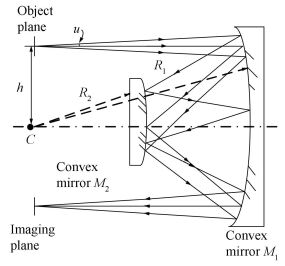
3 Introductions of the Two Concentric Grating Spectrometers 3.1 Offner Convex Grating SpectrometerOffner form consists of a concave mirror (M1) and a convex mirror (M2) with radius of R1 and R2 respectively, and the two mirrors have a common center C as shown in Fig. 1, where u is the aperture angle and h is the height of the object. M2 is the system stop and is located around the focal plane of M1. Therefore, the design is telecentric. It is obvious that Offner form is symmetrical and its magnification is-1. Spherical aberration and astigmatism are the only two aberrations needing to be considered, benefiting from the symmetry. Besides, there is no need to worry about chromatic aberration, because all optical elements are mirrors. Only when the concentricity and the equation R2 = R1/2 are fulfilled simultaneously [17-19], the system have the least aberration. But Offner form is still limited by spherical aberration, and the inclination of the meridional image field at h is approximately proportional to 1/F3.
|
Figure 1 Schematic of Offner concentric system |
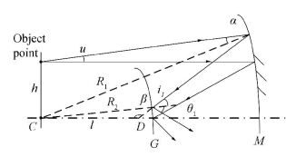
Replacing M2 by a convex reflection grating (G) will get Offner convex grating spectrometer. The diffraction characteristics of it can be obtained according to Fig. 2, where l is the length from point C to point D, and α is the incident angle of M, and β is the angle forming by optical axis and reflective ray from M, and i1 and θ1 is the incident angle and diffraction angle of G respectively.
|
Figure 2 Diffraction schematic of Offner spectrometer |
The following equations are acquired according to the sine theorem referred to Fig. 3.

|
Figure 3 Schematic of Dyson concentric system |
| $\begin{array}{*{20}{c}} {\frac{{\sin \alpha }}{h} = \frac{{\sin \left( {{{90}^ \circ } + u} \right)}}{{{R_1}}}}\\ {\frac{{\sin \beta }}{{{R_1}}} = \frac{{\sin \alpha }}{l}}\\ {\frac{{\sin {i_1}}}{l} = \frac{{\sin \beta }}{{{R_2}}}} \end{array}$ |
and hence
| $\sin \alpha = \frac{{\cos u}}{{{R_1}}}h$ | (6) |
| $\sin {i_1} = \frac{{\sin \alpha }}{{{R_2}}}{R_1}$ | (7) |
In order to avoid obscuration of rays, h should be
| $h = {R_1}\tan u$ | (8) |
Offner spectrometer obeys the function
| $d\left( {\sin {i_1} - \sin {\theta _1}} \right) = - \lambda $ | (9) |
From Eqs. (6)-(9), θ1 can be acquired:
| ${\theta _1} = \arcsin \left( {\frac{\lambda }{d} + \frac{{{R_1}\sin u}}{{{R_2}}}} \right)$ | (10) |
Dyson form consists of a plano-convex lens and a concave mirror, and the lens and the mirror share a common center C, as shown in Fig. 3. The concave mirror is the system stop and it is located around the focal plane of the plano-convex lens. The system is a telecentric system with magnification of +1. So there is a relation between R and r as
| $R = \frac{n}{{n - 1}}r$ |
where n is the refractive index.
Dyson form is free from all Seidel aberrations without restriction of aperture, but it also suffers from high order aberrations. The aberrations will cause a distance of s departing from the ideal position of the image along the axis, and s can be expressed as
| $s = \frac{{n\left( {n - 1} \right){h^4}}}{{{r^3}}}{\cos ^3}u$ |
It is obvious that the u makes less contribution to s[3].
Dyson form is catadioptric, and we have to select applicable material to fabricate the plano-convex lens.The material should possess high transmission over 8-12 μm and should have high Abbe number to reduce the chromatic aberration. We select ZnSe because its Abbe number is higher (58.61), and its absorption coefficient is lower ( < 0.000 5).
It will be Dyson concave grating spectrometer after substituting the concave mirror with a concave reflection grating. The diffraction characteristics of Dyson spectrometer can be obtained according to Fig. 4, where θ2> represents diffraction angle.

|
Figure 4 Diffraction schematic of Dyson spectrometer |
Dyson spectrometer obeys the following function
| $d\left( {\sin \;{i_2} + \sin \;{\theta _2}} \right) = \lambda $ |
Obviously incident angle i2 equals to 0, the diffraction angle θ2> is as
| ${\theta _2} = \arcsin \left( {\frac{\lambda }{d}} \right)$ | (11) |
From the descriptions above, we can infer the characteristics of Offner form and Dyson form as: (1) Offner form is not suitable in lower F-number system while Dyson form is, (2) In comparison of Eq. (10) to Eq. (11), it can be seen that θ1 is bigger than θ2>, and so the off-axis aberration of Offner is higher, and (3) According to Eq. (10), θ1 is bigger in the system with large numerical aperture.
F-number has effect on the throughput and grating constant has effect on the volume, and the throughput and the volume are both important parameters in LWIR imaging spectrometer. Therefore, we compare Offner form and Dyson form in different F-numbers and different grating constants.
4 Comparison in Different F-numbersThe performance of Offner spectrometer is limited by aperture angle, and it is said that NA should be less than 0.18 if we want to get good imaging [20]. The relationship between the numerical aperture of NA and the F-number of F/# is as
| $NA \approx \frac{1}{{2F/\# }}$ | (12) |
F1/# approximately equals 2.8 when NA=0.18 according to Eq. (12). Because SNR is proportional to 1/ (F/#) 2 theoretically in infrared system, we set F2/# to be 2 which is 2-1/2 times of F1/#. The grating pitch can be actually manufactured quiet small, but d must be higher than 18.75 μm to enable θ1 less than 90° according to Eq. (11). At last, we pick up the grating constants of 100 μm and 40 μm in our designs in terms of the off-axis aberration in Offner form.
All of the parameters needed have been provided. Then we compare Offner form and Dyson form in different F-numbers firstly, and all of the indicators are listed in Table 1.
| Table 1 Indicators for spectrometer design |
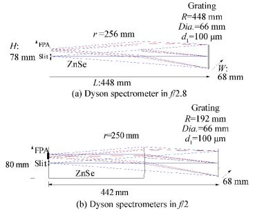
For comparison, we design two Dyson spectrometers with spherical surfaces, as shown in Fig. 5. From Fig. 5, we can see that each wavelength can be focused well, which implying both of them can realize ideal imaging. Fig. 5(a) is with F-number of 2.8, and Fig. 5(b) is with F-number of 2. Both of the spectrometers can realize spectral resolution of 15.6 nm, and are with similar volume.
|
Figure 5 Two Dyson spectrometers with different F-number |
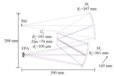
Then we design two Offner spectrometers. Fig. 6 shows the designed spectrometer with F-number of 2.8. It can be seen that the ideal imaging can be realized. With this spectrometer, spectral resolution of 15.6 nm can be realized. The one with F-number of 2 fails to perfect imaging due to large aberrations, especially spherical aberration. Fig. 7 shows geometric spot diagrams of the designed system, where the center circles show Airy disk. It can be seen that the spots are much bigger than Airy disks, implying unacceptable imaging quality.
|
Figure 6 Offner spectrometer in f/2.8 |

|
Figure 7 Geometric spot diagrams for f/2 Offner spectrometer |
We make suitable decenter of M1, G2 and M3 from the axis vertically, and then set M1 and M3 as aspherical surfaces. A better system is obtained, and Fig. 8 shows the geometric spot diagrams of the system. It can be seen that the sizes of spots are improved greatly, but still larger than Airy disks.
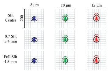
|
Figure 8 Geometric spot diagrams for the corrected Offner spectrometer |
Obviously, Offner form is suitable only for the system with larger F-number, while Dyson form can meets the requirement of system with smaller F-number. The spherical aberration existing in Offner spectrometer with smaller F-number cannot be corrected perfectly. With the same F-number, Dyson form owns a smaller volume because of its catadioptric optical structure. On the other hand, Offner form is of reflective optical structure, inevitably resulting in longer off-axis length, and this makes its volume bigger.
5 Comparison in Different Grating ConstantsIn this part, we will compare Offner form and Dyson form in different grating constants, and all of the indicators are listed in Table 2.
| Table 2 Indicators for spectrometer design |
For comparison, we design two concentric spectrometers of a lower d with spherical surfaces. Dyson form can realize ideal imaging, as shown in Fig. 9. The spectral resolution can still reach 15.6 nm. Offner spectrometer can realize ideal imaging as well, but its spectral resolution cannot be 15.6 nm because of the large geometric spots as shown in Fig. 10.

|
Figure 9 Dyson spectrometer with d2 of 40 μm |
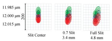
|
Figure 10 Geometric spots of Offner spectrometer with d2 of 40 μm |
In order to correct the aberrations, we make suitable decenter of M1, G2 and M3 from the axis vertically, and then set M1 and M3 as aspherical surfaces as before. The designed structure is shown in Fig. 11. Its spectral resolution can reach 15.6 nm.
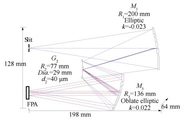
|
Figure 11 Corrected Offner spectrometer with d2 of 40 μm |
Design results clearly show that, just with spherical mirror, Dyson spectrometer has better imaging quality with a lower grating constant, and therefore higher spectral resolution with smaller size of system can be realized. Although imaging quality of Offner form with lower grating constant is worse, it can be improved by decentering and aspherizing.
6 Design of Dyson Spectrometer with Better PerformancesIt can be inferred that Dyson form has ideal imaging in lower F-number and lower grating constant from the comparisons. In practice, the packaged focal plane in chip carriers should be laterally separated from the slit, and more importantly, the wire bonds and protective windows make it necessary that there should be an axial gap between the image plane and the rear face of Dyson lens [21-22]. In this case, Dyson form may lose its advantage of perfectly imaging. Spherical aberration is the main aberration and so we introduce an aspheric corrector nearby the stop. We design a Dyson spectrometer with f/2 and grating constant of 40 μm with corrector lens, as shown in Fig. 12.
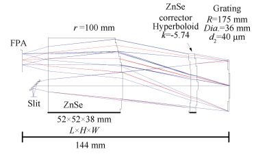
|
Figure 12 Dyson spectrometer in f/2 and d of 40 μm with corrector lens |
Finally, we have designed a cooled Dyson LWIR imaging spectrometer. We choose three-mirror off-axis aspherical optical system as the fore-optics and adopt re-imaging to realize 100% cold stop efficiency. The imaging spectrometer is with the size of 300 mm×250 mm×116 mm, the spectral resolution of 25 nm and the spatial resolution of 0.2 mrad.
7 ConclusionsTwo typical concentric spectrometers are designed, and both of them possess the advantages of simple and compact structure. Compared to Offner form, Dyson spectrometer can realize ideal imaging in lower F-number with even smaller volume just with spherical mirror.Thus it can meet the requirements of high signal-to-noise ratio and miniaturization in LWIR imaging spectrometer. In terms of Offner spectrometer, the realization of miniaturization is easier as compared with the realization of high throughput. All of the comparisons are tabulated in Table 3.
| Table 3 The comparison of Offner form and Dyson form |
| [1] |
Offner A. New concepts in projection mask aligners.
Optical Engineering, 1975, 14(2): 130-132.
( 0) 0)
|
| [2] |
Seo Hyun Kim, Hong Jin Kong, Soo Chang. Aberration analysis of a concentric imaging spectrometer with a convex grating.
Optical Communications, 2014, 333: 6-10.
DOI:10.1016/j.optcom.2014.07.028 ( 0) 0)
|
| [3] |
Dyson J. Unit magnification optical system without Seidel aberrations.
Journal of the Optical Society of America, 1959, 49(7): 713-716.
DOI:10.1364/JOSA.49.000713 ( 0) 0)
|
| [4] |
Carlos Montero-Orille, Xesús Prieto-Blanco, Héctor González-Núñez, et al. Design of Dyson imaging spectrometers based on the Rowland circle concept.
Applied Optics, 2011, 50(35): 6487-6494.
DOI:10.1364/AO.50.006487 ( 0) 0)
|
| [5] |
Mertz L. Concentric spectrographs.
Applied Optics, 1977, 16(12): 3122-3124.
DOI:10.1364/AO.16.003122 ( 0) 0)
|
| [6] |
Lobb D R. Theory of concentric design for grating spectrometers.
Applied Optics, 1994, 33(13): 2648-2658.
DOI:10.1364/AO.33.002648 ( 0) 0)
|
| [7] |
Mouroulis P. Compact infrared spectrometers.
Proceedings of SPIE, 2009, 7298: 729803.
DOI:10.1117/12.817358 ( 0) 0)
|
| [8] |
Francis Reininger, Coradini A, Capaccioni F, et al. VIRTIS: visible infrared thermal imaging spectrometer for the Rosetta mission.
Proceedings of SPIE, 1996, 2819: 66-77.
DOI:10.1117/12.258082 ( 0) 0)
|
| [9] |
Arnold G E, Haus R, Kappel D, et al. VIRTIS/VEX observations of Venus: overview of selected scientific results.
Journal of Applied Remote Sensing, 2012, 06: 6358.
DOI:10.1117/1.JRS.6.063580 ( 0) 0)
|
| [10] |
Green R O, Pieters C, Mouroulis P, et al. The Moon Mineralogy Mapper imaging spectrometer science measurement characteristics and laboratory calibration results.
In Proceedings of IEEE Aerospace Conference, Piscataway:IEEE, 2008: 1-5.
( 0) 0)
|
| [11] |
Mouroulis P, Gorp B V, Green R O, et al. Portable remote imaging spectrometer coastal ocean sensor: design, characteristics, and first flight results.
Applied Optics, 2014, 53(7): 1363-138.
DOI:10.1364/AO.53.001363 ( 0) 0)
|
| [12] |
Warren D W, Boucher R H, Gutierrez D J, et al. MAKO: A high-performance, airborne imaging spectrometer for the long-wave infrared.
Proceedings of SPIE, 2010, 7812: 78120N 1-78120N-10.
DOI:10.1117/12.861374 ( 0) 0)
|
| [13] |
Hall J L, Boucher R H, Gutierrez D J, et al. First flights of a new airborne thermal infrared imaging spectrometer with high area coverage.
Proceedings of SPIE, 2011, 8012: 801203.
DOI:10.1117/12.884865 ( 0) 0)
|
| [14] |
Wang Jianyu, Li Chunlai, Ji Hongzhen, et al. Status and prospect of thermal infrared hyperspectral imaging technology.
Journal of Infrared and Millimeter Waves, 2015, 34(1): 51-59.
( 0) 0)
|
| [15] |
Liu Yujuan, Cui Jicheng, Bayanheshig, et al. Design and application of imaging spectrometers with convex gratings.
Optics and Precision Engineering, 2012, 20(1): 52-57.
DOI:10.3788/OPE. ( 0) 0)
|
| [16] |
Liu Zihan, Ji Yiqun, Shi Rongbao, et al. Optical design of airborne infrared pushbroom imaging spectrometer.
Infrared and Laser Engineering, 2014, 43(9): 2941-2946.
( 0) 0)
|
| [17] |
Akiyoshi Suzuki. Complete analysis of a two-mirror unit magnification system. Part 1.
Applied Optics, 1983, 22(24): 3943-3949.
DOI:10.1364/AO.22.003943 ( 0) 0)
|
| [18] |
Akiyoshi Suzuki. Complete analysis of a two-mirror unit magnification system. Part 2.
Applied Optics, 1983, 22(24): 3950-3956.
DOI:10.1364/AO.22.003950 ( 0) 0)
|
| [19] |
Huang Yuanshen, Zhu Dongyue, Li Baicheng, et al. Non-approximate method for designing annular field of two-mirror concentric system.
Chinese Optics Letters, 2012, 10(3): 032201.
DOI:10.3788/COL ( 0) 0)
|
| [20] |
Kwo D, Lawrence G, Chrisp M. Design of a grating spectrometer from a 1:1 Offner mirror system.
Proceedings of SPIE, 1987, 818: 275-279.
DOI:10.1117/12.978898 ( 0) 0)
|
| [21] |
Warren D W, Gutierrez D J, Keim E R. Dyson spectrometers for high-performance infrared applications.
Optical Engineering, 2008, 47(10): 103601.
DOI:10.1117/1.2995993 ( 0) 0)
|
| [22] |
Xue Qingsheng. Modified Dyson imaging spectrometer with an aspheric grating surface.
Optical Communications, 2013, 308: 260-264.
DOI:10.1016/j.optcom.2013.07.048 ( 0) 0)
|
 2017, Vol. 24


