As is well-known, metal plastic forming is widely used in manufacturing industries. It generally includes sheet stamping and bulk forging. Metallic parts with large specific surface play a non-substitutable role in the mechanical industry[1]. Conventional stamping processes are adopted to make this kind of parts from sheet metals, but the thickness distribution is difficult to be controlled due to the approximate plane stress when the blank is deformed. The thickness of formed parts generally reduces around corners and increases in the edge[2]. Furthermore, functional elements, such as bosses, teeth, steps, ribs, etc. can not be made due to the tension stress state. Forging can make parts with functional elements due to the three-dimensional stress state when the billets are deformed. However, it is limited to form prats possessing features of small thickness and large contour size due to the high load requirements during forging with bars or block billets.
The demand for lightweight metallic products with customized properties, large specific surface, and functional elements has been increasing in various industrial fields, such as automobile, aircraft, electronics and so on. Usually, to obtain the expected characteristics of workpieces, complex technical processes and tools are required, which can be very resource-intensive and time-consuming. Furthermore, to reduce the production cost, net-shape and near-net-shape forming technologies without subsequent finishing operations are increasingly required.
Stamping-Forging processes (SFPs) are a class of novel processes combining stamping and forging together, to manufacture functional elements within sheet metal parts, in which only specific regions of blanks are formed[3]. For example, cup parts with gears and thickened walls can be manufactured by combining drawing and upsetting; tailored blanks can be formed by drawing and reverse flatting. Comparing to conventional forging or stamping operations, the need for additional machining steps can be reduced, as well as the load applying on tools.
The aim of this paper is to review the state-of-the-art SFPs and their applications and to provide a guide for researchers and engineers working in this field. In this paper, various SFPs are classified according to the combination ways of stamping and forging operations. For each class, the basic process principle is given, with its typical applications discussed.
2 Classification of SFPsMerklein et al.[4] introduced SFPs based on tool motion, as well as sheet thinning and sheet thickening based on sheet thickness variation, while Nakano et al.[5] introduced SFPs according to part cross-sections. In recent years, many new SFPs were developed.Generally, a specific combination of stamping and forging operations can make parts with specific features. For a better understanding and to provide a guide for researchers working on metal forming, in this paper, SFPs are classified according to the combination way of stamping and forging operations, as shown in Table 1. Each class and related process principle are discussed in details in the following sections.
| Table 1 Classification of SFPs according to combination way |
3 Combined Forming Method 3.1 Combination of Drawing/Flanging with Upsetting
Parts with thickened walls or functional elements on the wall can be fabricated by the combination of drawing/flanging with upsetting. In this combination, a vertical wall is firstly formed by drawing or flanging, and then an upsetting operation is taken to increase the wall thickness or form functional elements.
This process has the widest application in manufacturing parts with thickened walls. Wang, et al.[6] and Luo et al.[7] thickened the outer wall of a pan to form a flywheel panel used in cars. As shown in Fig. 1, the sheet was drawn into the die by an inner punch, and then the wall was compressed axially to be thickened. Finally, the wall was thickened from 10 mm to 11 mm.

|
Figure 1 Forming of a pan with thickened wall |
Suzumura et al.[8]developed a combined process to form a step-shaped cup with thickened flange. As shown in Fig. 2, During the cup bottom, was drawn by the inner punch, the edge of the cup was upset by the outer punch. As the wall and the flange were constrained by the outer die, the buckling was prevented. The final thickness can be adjusted by changing the inner and outer punch strokes. The movement of punches was controlled by a multi-action press.

|
Figure 2 Forming process of a step-shaped cup with thickened flange[8] |
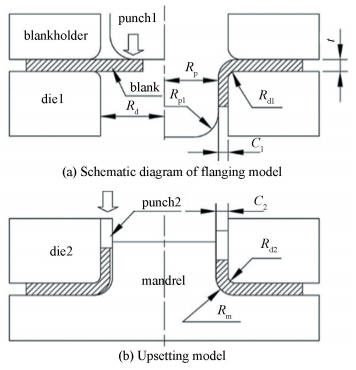
Luo et al.[9]thickened the inner wall of holes by combining hole flanging and upsetting. A round blank with a center hole was flanged first to form a vertical wall, then the wall was held by an inner mandrel together with an outer die and upset for three times, as shown in Fig. 3. Yan et al.[10]also investigated the flanging-upsetting process, with the effects of die radius and die clearance on the flanging and upsetting discussed and an optimized wall upsetting ratio of 1.25 obtained. Wu et al.[11]utilized a similar process to make clutch hubs, so as to obtain flange corners with smaller radii and less thinning.
|
Figure 3 Process of hole flanging and upsetting[9] |
Wang et al.[12]and Luo et al.[13]developed a multi-step process to form double-cup parts with thickened inner walls, as shown in Fig. 4. In the first step, a round blank was deformed to form a cup by forward drawing. In the second step, a center boss was formed by a powerful backward drawing, in which, the flange was pushed axially while the boss was drawn. In the third step, the bottom of the boss was pierced and flanged to form a straight inner wall. And then, the inner wall was thickened by taking several upsetting operations in the last step.

|
Figure 4 Forming process of a double-cup part with thickened inner wall[13] |
Except for manufacturing parts with thickened walls, this combination can also be used to manufacture parts with functional elements on the wall. Bedford et al.[14]developed a process by combining drawing and upsetting to manufacture gear parts. The active tool elements are depicted in Fig. 5(a) and the operation sequences are shown in Figs. 5(b)-(d).Firstly, a deep drawing process without a blank holder was employed to form the semi-finished sheet plate. In this step, a tractrix curve shaped drawing radius was used to reduce the forming force and the burr formation when the wall passed through the tooth cavity.After deep drawing, the upsetting of the cup wall was taken to force the material to flow into the tooth cavities of the die, and thus the external gear with 38 teeth was finally formed. The difficulty of combining drawing and upsetting to form gears is to control the material flow, so as to overcome the folding at the corner between the wall and the web.

|
Figure 5 Forming of gear[14], tool active elements and main processes |
According to studies mentioned above, the combination of drawing/flanging and upsetting can be taken in sequence or one step. Conventional hydraulic presses or mechanical presses can be employed for the process when taking in sequence, but a multi-action press is required when taking in one step. However, the wall tends to buckle, which easily leads to folding. Hence, the thickening ratio in a single step is limited. To obtain greater thickness, a multi-stage thickening process should be employed. Thus, the combined process conducting in sequence is a better choice when the thickening ratio is larger. If combining stamping and thickening in one step, the die set is complicated and a multi-action press is required. Due to the friction resistance, the difficulty of material flow increases with the wall height, resulting in a small allowable wall height. Furthermore, the combination of drawing/flanging with upsetting can not be used for parts with thickened portions not in the wall, such as tailored blanks and parts with thickened bottom, since the load cannot be directly applied to the plate.
3.2 Combination of Drawing with Reverse FlattingIn this combination, the blank is firstly drawn to form a cup or a groove, and then the cup or groove is flatted with the other portion clamped by a flat punch. The punch vertically compresses the blank to plane, while the punch force is changed to an in-plane force to compress the target portion. Via compression, the target portion was thickened. This combination can be used for manufacturing tailored parts and bottom thickened parts.
3.2.1 To form tailored partsThe combination of drawing with flatting is most widely used for making tailored blanks which are used to make parts with thickened corners.
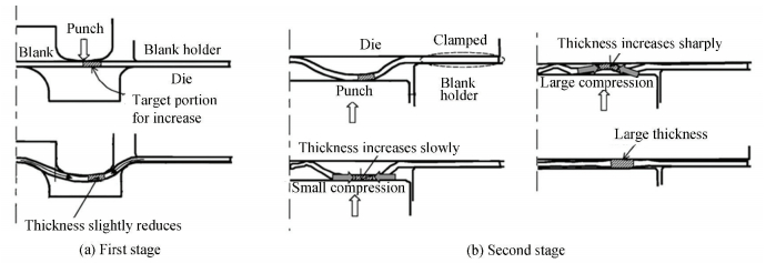
Zhao et al.[15]developed a drawing-pressing forming process to thicken the central area of a round sheet metal. As shown in Fig. 6, in the first step, the central portion of the round blank was drawn into the die. In the second step, the out rim of the workpiece was restrained, while the center portion was flatted and thickened by a reverse compression. Tan et al.[16] developed a two-stage forming process to manufacture tailored blanks. In the first stage, the target portion of the blank was drawn into a die. In the second stage, the target portion was reversely compressed by a flat die with a flange clamped to increase the thickness, as shown in Fig. 7.

|
Figure 6 Thickening process of the center of disc-like parts[15] |
|
Figure 7 Two-stage forming process of tailor parts with local thickening[16] |
Since the thickness reduction of the drawn part corner leads to a poor mechanical property, some engineers have to make tailor blanks with annular thickened zones as preforms to increase the corner thickness. Abe et al.[17]developed a three-stage stamping process including bottom thickening and corner flanging for a cup with a flange.In the first and second stages, the cup with a conical bottom was formed by drawing using conical punches, and the volume of the conical bottom was larger than that of the flat bottom. In the third stage, with the flange being clamped between the blank holder and the die, the conical bottom was compressed into a flat one by both the counter punch and inner punch, resulting in increased thicknesses around the bottom and flange corners. Finally, the flange corners and wall thicknesses around the bottom were increased by about 10%, as shown in Fig. 8.

|
Figure 8 Three-stage stamping process and relative section[17] |
In these processes, the drawing depth is the key factor for thickening. If the drawing depth is too large, the thickness increase of the center portion becomes un-uniform or the blank folds in the reverse compression step. Otherwise, the thickening ratio is not large enough. Thus, multiple steps are required to ensure the thickening ratio. This process can be achieved by presses with translational movements, such as hydraulic presses and mechanical presses.
3.2.2 To form bottom thickened partsThe combination of drawing and compression can also be used to make parts with thickened bottom. Jin et al.[18]manufactured aluminum alloy shell parts with non-uniform thickness by using a single-step hot stamping forging process. In this process, a die-set with floating seat was employed.As shown in Fig. 9, the die was installed in a stationary seat and fixed together. The counter punch was installed on a spring-supported floating seat. In the beginning, the blank was placed on the top of the die. Then, the punch descended to deform the workpiece, and the workpiece pushed the counter punch downward. In this process, a convex bottom was firstly formed, and the material in the wall was squeezed into the bottom during drawing. After that, the bottom was compressed and thickened from 4 mm to 4.25 mm.

|
Figure 9 Forming process of a pan with thin wall and thickened bottom[18] |
In this process, the initial interposition of counter punch is the key factor for bottom thickening. An over-large initial interposition results in a small thickening ratio, otherwise, a non-uniform bottom will be formed. The merit of this process is that both drawing and flatting are achieved in only one step, and the shortcoming is that the volume of material squeezed into the bottom from the wall is difficult, resulting in a high forming load and small thickening ratio of the bottom.
3.3 Combination of Bending with CompressionThe combination of bending and compression was generally employed for manufacturing tailored blanks having straight thickened portions. In this process, a uniform sheet was firstly bent into a hat shape to get two inclined portions, and then these portions were compressed to be thickened by a flat die. Mori et al.[19]employed this process twice to realize two perpendicular groups of thickened areas, and the thickness at the four corners was doubled, as shown in Fig. 10. The critical height of the drawn square cup reached 28.3 mm for the tailored blank, while that was 21.3 mm for the uniform blank. Wang et al.[20]developed a bending-compression process to shorten and thicken the connecting portion of a bracket shown in Fig. 11. Since the sum of the two walls' heights was larger than the distance between them, the connecting portion should be shortened. Hence, the connecting portion was firstly bent to a U-shape and then compressed with two ends fixed by a flat punch. Then, the compressed portion was thickened and shortened.

|
Figure 10 Bent-compressed tailored blanks and drawn parts[19] |

|
Figure 11 Bending-compression process for a bracket[20] |
According to the process described above, this process can be used not only for manufacturing tailored blanks but also for shortening sheets. The key factor of this process is the inclined wall or convex height of the bent portion, that is, a larger height leads to folding in compression similar to that in drawing-reverse compression processes. Comparing to the process described in section 3.2, in this process, the thickened zone is straight as the blank is bent along a line.
3.4 Combination of Drawing with Extrusion/IroningIn this combination, a blank is drawn into a cup, and then a subsequent ironing or extrusion is applied to form thinned wall, step-shaped wall or wall with functional elements.
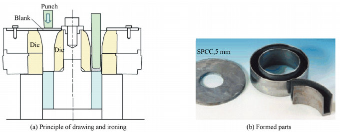
When an ironing process was applied to a drawn workpiece, not only the wall thickness was thinned, but also the uneven wall thickness distribution was eliminated. Nakano et al.[5]developed an integrated combination process of drawing and ironing for producing double-cup parts with thinned walls, as shown in Fig. 12. The wall of the product was reduced to a thickness of 1.5 mm from a plate with 5 mm thickness, with a good fabrication accuracy.
|
Figure 12 Ironing process for the side wall[5] |
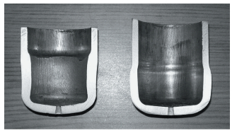
This combination can be used for parts with step-shaped walls, such as tubes and cups. Mori et al.[2] introduced an integrated process of drawing and extrusion/ironing for a thin-wall tube as displayed in Fig. 13. Via extrusion and ironing, the steps, different thicknesses, and sharp corners can be formed. Kampuš et al.[21] superimposed force on the cup edge in a combined process of upsetting and ironing operation, and obtained a cup with the external or internal wall thickened (see Fig. 14).

|
Figure 13 Extrusion of thin-wall tube[2] |
|
Figure 14 Cups with thickened wall made by deep drawing and ironing[21] |
This combination of drawing with ironing can not only process simple cylindrical workpieces. Zhuang et al.[22]proposed a hybrid method of deep drawing and extrusion to produce geared drums using a servo-controlled press, as shown in Fig. 15. In this process, specifically designed oscillation motions and step motions were adopted in the hybrid deep drawing and extrusion process. The results showed that the surface quality of parts was obviously improved and the extent of thickness reduction was reduced when using a step motion in the early stage of the process.

|
Figure 15 Forming process of gear drum[22] |
Mori et al.[23]developed a hot forming process for gear drum from an ultra-high strength steel. The sequence of this novel spline forming process was illustrated in Fig. 16. In Fig. 16(a), the cup wall was electrified to heat between the upper and lower electrodes. And then, the two electrodes were moved away by air cylinders, as shown in Fig. 16(b). Finally, the cup was drawn through the die by a punch to form the teeth (see Fig. 16(c)). To realize the sequence of heating, releasing and forming, an 800 kN CNC servo press was synchronized with the power supply for heating and air cylinders for the electrodes while moving. The difficulty of this process for manufacturing gears was controlling the material to full fill the tooth top.

|
Figure 16 Forming of cups with spline using resistance heating[23] |
Drawing can also be combined with backward extrusion. Wang et al.[24] proposed a new combined process of drawing and compression to form a cup with solid bosses from a plate. Fig. 17(a) shows the process principle. When the die was moving upward, and the blank was drawing, a constant punch load was applied to the bottom. Thus, a boss was extruded in the bottom when the plate was compressed.

|
Figure 17 Forming of the cup with solid bosses[24] |
In order to investigate the influence of the boss position on the boss forming behavior, a double-boss model (as shown in Fig.(17c)) was studied. The distance from the boss center to the cup center changed in the range of 3-13 mm. Figs. 17(d) and (e) compare the cross sections of the cup obtained by simulation and experiment. The experimental result shows a good agreement with that of the simulation.
Sheng et al.[25]proposed a hybrid forming process by combining the warm drawing and hot extrusion to produce cup parts with inner ribs.In which a sheet was firstly drawn to form a preform at warm forming temperature, and then the preforms were hot extruded to the desired geometry, as shown in Fig. 18.

|
Figure 18 Illustration of the hybrid-forming process[25] |
Lin et al.[26]formed hollow parts having flange from sheet metals by combining drawing and cold extrusion. As shown in Fig. 19(a), firstly, a cup-shaped workpiece with a center hole was formed by drawing. Secondly, it was put into the die cavity. The punch and the moveable die extruded the rim of the workpiece together to form a flange in the center of the cup bottom at the back face. During this process, the cup was positioned by the cup holder and the movable die. The formed workpieces were shown in Figs. 19(b) and (c).

|
Figure 19 Forming of hollow flanged parts[26] |
The combination of drawing with ironing/forward extrusion is favorable for making thinned wall parts or gears. The key factor of this combination is the entrance shoulder angle of the die. An excessively low angle will lead a large deformation zoom, resulting in a serious friction force. Furthermore, the angle is limited to the step shape of the part wall in some cases. A too large angle will make the material flow difficultly. As the wall mainly deforms in tension when forming gears, the material is difficult to fill the tooth tip. The merit of drawing combined with backward extrusion for forming cups with solid bosses is that the radial tensile force in the bottom can make the material in the bottom flows outward, resulting in a lower flow stress. Thus, the forming load is decreased. Meanwhile, a thicker blank is required for compensating the material flow to the wall from the bottom. Compared to the conventional hole flanging, the advantage of making hollow flanged parts by this process is that the forming limit is much higher.
3.5 Combination of Blanking with ForgingSome stamping processes can also be combined with die forging processes. Hui et al.[27]combined a blanking process with a closed-die forging to manufacture an aviation connector, as shown in Fig. 20. Firstly, the main shape of the part was made by fine blanking, and then the branches were bent, finally, the small boss was formed by a closed-die forging. Li et al.[28]developed a process by combining drawing with closed-die forging to form an automobile clutch bush. In the first step, the preformed blank was drawn into the cavity die by a flat punch. When the up punch reached a certain depth, it compressed the center portion of the workpiece together with a lower punch having a conical end to make the material flow into the corner. In the second step, a lower punch with chamfered end was used instead of the conical one, with the compression of the two punches, more materials were driven to the corner. Thus the corner was thickened, as shown in Fig. 21.

|
Figure 20 Forming of aviation connector[27] |

|
Figure 21 Forming of a clutch bush[28] |
In these processes, as the stress is very high in closed-die forging, the forging area is generally small.
4 Sheet Forging Method 4.1 ExtrusionThe characteristic of extrusion is that the material flows in the direction or the opposite direction of the punch under compression.
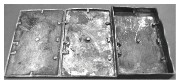
Zhang et al.[29]proposed a backward extrusion of AZ31B magnesium components at 250 ℃, as shown in Fig. 22. He also applied this process to form magnesium-alloy notebook cases with complex geometries as shown in Fig. 23, in which sidewalls, hooks, and bosses of the case were formed synchronously[30]. Wang et al.[31]formed a cooling fin from 1100-H14 aluminum alloy sheets using backward extrusion (Fig. 24), and Sun et al.[32]investigated the effects of process parameters on the boss forming (Fig. 25).Chen et al.[33]also studied embossment formation in the backward extrusion of AZ31 magnesium-alloy sheets. The results indicated that the thicker the blank is, the better the embossment can be formed. Also, the greater the friction coefficient is, the better the embossment can be done. But the increased friction will lead to an increased forming load and reduce the sidewall uniformity.

|
Figure 22 FEM simulation of forming process and experiment results[29] |
|
Figure 23 Press-forged cases at different punch strokes[30] |

|
Figure 24 Formed cooling fin[31] |

|
Figure 25 Formed part with boss[32] |
Extrusion can also make bosses in both sides of a sheet, and if the section change is large, multi-step is required. Cai et al.[34] developed a multiple step extrusion to manufacture a load-bearing disk, as shown in Fig. 26.

|
Figure 26 Forming of the load-bearing disk[34] |
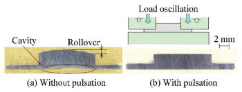
In plate extrusion, as the punch pressing the blank in the plane, the contacted area is large. Hence, it is hard for the material to flow and the material between the punch and die suffers from high hydrostatic pressures, resulting in a very large punch load. Thus, the key issue of this process is to decrease the punch load and promote the material flowing to the boss. For this purpose, Maeno et al.[35]applied load pulsation into the forging of a stainless steel sheet to form a boss without cavity and rollover, as shown in Fig. 27. The load pulsation can effectively improve the forming shape as well as decrease the forming load.
|
Figure 27 Comparison of stainless steel parts with a boss formed without and with pulsation[35] |
Extrusion can also be used for plane gear forming. Hetzner et al.[36]formed plane gears by compressing a sheet using a punch with geared ends. In their study, two FEA simulations were carried out, one with a global friction factor of m = 0.12, and the other one with locally adapted friction factors, m = 0.3 and m = 0.05 in front of and behind the teeth, respectively, as shown in Fig. 28(a). The results indicated the material flow could be obviously improved by changing the friction condition.

|
Figure 28 Definition of frictional zones and comparison of material filling[36] |
Compared to extrusion in bulk forming using block or bar, the material thickness is much smaller, and the friction force resists material flow in-plane greatly, resulting in a high punch pressure. Thus, measures for reducing friction, such as better lubrication, load pulsation, and tailored die surface, should be taken.
4.2 SpinningIt is well known that spinning is a flexible incremental forming process suitable for asymmetrical parts. The forming load is relatively low, since the workpiece deforms gradually under the partial tool contact. Conventionally, this process is used to form tabular parts or cup parts with thinned walls or wall thicknesses equal to those of original blanks. With the development of this process, it can be used for manufacturing parts with thickened walls or other functional elements.
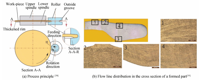
4.2.1 Spinning for rim thickeningFor parts with thick rims and thin web plates, Wang et al.[37-38]proposed a new rotary forming process, as shown in Fig. 29. In the proposed process, a workpiece was sandwiched between the upper spindle and lower spindle, with all of them rotating together. A roller with an outside groove compressed the workpiece in the radial direction to thicken the rim. The forming process stopped when the roller contacted the spindle. In this study, the effect of groove shape on the forming result was also investigated. It was proved that the groove angle played the dominant role. Jin et al.[39]studied the metal flow in this process. The flow line revealed that the material was not only compressed in the radial direction but also driven to flow in the tangent direction in the outer side of the rim.
|
Figure 29 Rim thickening process |
In this process, as the rim is subjected to radial compression, it is easy to buckle, leading to a small thickening ratio. Multiple steps should be taken if a large thickening ratio is required. Moreover, the buckling is sensitive to the roller shape. Thus, the roller shape should be optimized.
4.2.2 Spinning for teeth or ribCup parts with inner teeth are widely used in automobiles. Xu et al.[40]developed a multi-pass stagger spinning process to form a gear with internal teeth from plate blank. Two passes, i.e., power spinning and drawing spinning, were designed for stagger spinning. It was shown that the using drawing spinning in the first pass is helpful for teeth forming in the second pass, as shown in Fig. 30. Xia et al.[41] and Ma et al.[42] also employed this process to manufacture clutch hubs with inner teeth.

|
Figure 30 Spinning of inner gears[40] |
Jiang et al.[43]manufactured a thinwalled tubular part with longitudinal inner ribs using backward ball spinning (Fig. 31(a)). The experimental results showed that the minimum ball diameter should be controlled to guarantee the occurrence of inner ribs. The minimum diameter of the ball is decided by the process parameters, i.e., the feed ratio, the reduction of wall thickness, the thickness of the blank and the material property. The experimental results indicated that a larger ball size contributed more to the metal flow stability and the formability of the inner ribs, but too large ball size resulted in poor surface quality.

|
Figure 31 Ball spinning of spun part[43] |
Transverse inner rib of conical parts is generally made by machining, but it will decrease the mechanical property and is not economical due to the low material utilization and long machining duration. Meanwhile, spinning has advantages when dealing with this kind of parts.
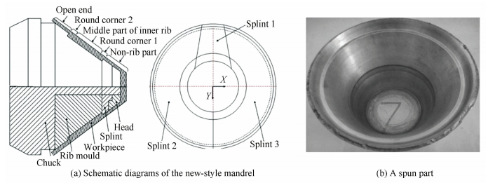
Ma et al.[44-45]formed conical parts with transverse inner ribs via a power spinning process. To form the transverse rib and take off the workpiece from the die, a mandrel with splint was used, as shown in Fig. 32.
Although cup-shaped or tubular parts with longitudinal inner ribs or teeth can be made by ironing or extrusion, only simple shapes are allowed due to the limitation of translational tool motion. This limitation can be avoided by making the tool to compress the material radially. Thus, spinning is a preferable selection for this kind of parts. For both inner longitudinal and transverse teeth/ribs, a mandrel with teeth is generally required. Especially, for parts with transverse teeth or ribs, a mandrel with splint should be employed to ensure demolding. Process parameters, such as feeding rate, significantly affect the forming results. Thus optimization of process parameters is the key issue of this process.
4.2.3 Spinning for sheet splittingExcept for manufacturing cup-shaped parts, spinning can also be used to split sheet blank partially, so as to form bosses or flanges.
In boss forming, the thickness of the plate is reduced, and the boss is formed by a conical roller as shown in Fig. 33[46]. Material flows towards a rotating mandrel and upwards to form a central boss. Xue et al.[47] employed this process to manufacture a pulley as shown in Fig. 34. Zhao et al.[48] employed this process to manufacture double-cup parts as shown Fig. 35.
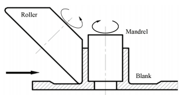
|
Figure 33 Principle of boss spinning[46] |
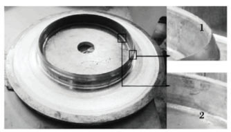
|
Figure 34 Pulley made by spinning[47] |

|
Figure 35 Principle of forming double cup part[48] |
In splitting forming, as shown in Fig. 36, the disk blank is fixed to a rotating spindle. While rotating, a roller moves radially onto the disk blank's edge and separates it into two flange areas[49]. This process can not only be used for materials with good plasticity at room temperature but also employed for hard-to-deform materials at elevated temperatures. For example, Huang et al.[50]adopted this process to manufacture TA15 titanium alloy parts.
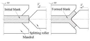
|
Figure 36 Principle of split spinning |
Both the boss forming and split forming are mainly used for pulleys or wheels. As the part is formed continuously and near net-shaped, boss forming and splitting forming have the advantages in lower forming load, smaller subsequent machining allowance, higher material utilization, more continuous metal fiber and relative higher product strength, when compared to conventional forging processes. For boss forming, its shortcoming is difficult to form the boss with a large thickness, because the wall thickness highly relies on the original blank thickness. For splitting spinning, the key issue is to overcome the buckling of the unclamped portion of the blank under a radial compression.
4.3 JoiningJoining is a widely used process for sheet connection and tube connection. Joining by plastic deformation is one of the commonly used connection methods.
Alves et al.[51]proposed a new process to join a sheet to a tube as shown in Fig. 37(a). Firstly, a mandrel was put in the center of the tube. Then the material of pipe end was piled-up and localized thickening produced by partial compression of the wall thickness along the longitudinal direction. In the second step, the upper tube end inserted in the sheet hole and was locked.

|
Figure 37 Sheet-bulk forming of thin-walled tubes for joining applications[51] |
The deformation of the sheet-bulk forming of tubes was limited by the occurrence of plastic instability and buckling for the ratio lgap/t > 10 between the initial gap length lgap and the final wall thickness t. Radial cracks along the outer radius of the piled-up material also developed due to the accumulation of ductile damages in cases with large values of initial gap length lgap.
Silva et al.[52]developed an overlapped lap joint process for tubes as shown in Fig. 38. In the first stage, the chamfered upper end of the lower tube was forced to insert into the lower end of the upper tube to make an overlap and an expansion of the lower end of the upper tube. The insertion depth was adjusted through the side clearance of the lower die. In the second stage, axial compression was applied, the overlapped tube ends beaded and was locked. In this process, a mandrel was used to ensure beading exclusively outwardly and guaranteed the inner diameter of the tube joint.

|
Figure 38 End-to-end joining of tubes by plastic instability[52] |
Bragança et al.[53]developed a process to join sheets perpendicular to one other, as shown in Fig. 39. In the process, one sheet had a rectangular hole (mortise) cutout, and another one had a tenon cutout in the edge. The tenon was longer than mortise and passed entirely through the mortise. Then, compression was applied on the end of the tenon to make plastic deformation and ensure a mechanical lock between the two sheets to be joined.

|
Figure 39 Schematic illustration of the new process[53] |
Currently, fastening, crimping, welding, brazing or adhesion are used for the joining of sheets or tubes. Each joining process offers advantages and disadvantages for specific applications. Compared with these processes, plastic joining is more environmentally friendly. In joining by plastic deformation, the key issue is to control the deformation zone to ensure the joint strength. Especially, the shape of the joint before deformation is decisive to the deformation process.
5 ConclusionsStamping forging processes (SFPs) are attractive for producing shell parts and tube parts with functional elements. In this paper, the processes were classified according to the combination way of stamping and forging operations, with each class of SFP reviewed in details. According to the available literature, most SFPs were developed in recent years, indicating that this process is a favorable means for manufacturing sheet parts with functional elements, but some aspects still require further investigations.
1) Comparing to conventional stamping or forging processes, the forming stress in the die or punch is much higher, while in many cases the punch size is small. Developing new die materials with high strengths is an urgent task.
2) Being different from conventional forming processes, as the SFP process includes stamping and forging, the Coulomb friction model and shear model cannot describe the friction behavior in this process, the influence of friction on material flow and forming load is much more significant. In some cases, the friction is beneficial for forming and goes against in other cases. Investigations of friction on the material flow and measures to utilize friction for material flow control are necessary. Developing new methods for better lubrication and die set for utilizing friction is also required.
3) With the development of SFPs, the action or function of the machine is much more complex, and an intelligent system is required, conventional forming machines can no longer meet the requirements. Thus, new machines with intelligent control and special functions, such as multi-action, oscillations units, compress-torsion units, etc., should be developed.
4) With the increasing demand for lightweight structures, more and more materials with high strength or ultra-high strength will be used. Meanwhile, deformation difficulty will accompany with the high strength in the forming. Thus, some new SFPs which can heat the material during forming should be developed.
| [1] |
Zhang S H, Chen S F, Ma Y, et al. Developments of new sheet metal forming technology and theory in china.
Acta Metallurgica Sinica-English Letters, 2015, 28(12): 1452-1470.
DOI:10.1007/s40195-015-0345-2 ( 0) 0)
|
| [2] |
Mori K, Nakano T. State-of-the-art of plate forging in Japan.
Production Engineering, 2016, 10(1): 81-91.
DOI:10.1007/s11740-015-0648-1 ( 0) 0)
|
| [3] |
Wang X Y, Ouyang K, Xia J C, et al. FEM analysis of drawing-thickening technology in stamping-forging hybrid process.
Forging & Stamping Technology, 2009, 34(4): 73-78.
DOI:10.3969/j.issn.1000-3940.2009.04.017 ( 0) 0)
|
| [4] |
Merklein M, Tekkaya A E, Brosius A, et al.
Overview on sheet-bulk metal forming processes. Düsseldorf: Verlag Stahleisen GmbH, 2011.
( 0) 0)
|
| [5] |
Nakano T. Compound technology of sheet metal forming and cold forging.
Journal of the Japan Scietety for Technology of Plasticity, 2001, 42: 388-392.
DOI:10.1016/j.proeng.2014.10.014 ( 0) 0)
|
| [6] |
Wang X Y, Luo W T, Xia J C, et al. Investigation of warm stamping-forging process for car flywheel panel.
Forging & Stamping Technology, 2009, 34(5): 43-46.
DOI:10.3969/j.issn.1000-3940.2009.05.013 ( 0) 0)
|
| [7] |
Luo W T.
An Investigation of Warm Stamping-Forging Process for Flywheel Panel of Automatic Transmission. Wuhan: Huazhong University of Science & Technology, 2009.
( 0) 0)
|
| [8] |
Suzumura T, Mine K, Hirayama I, et al. An experimental study of new redrawing method utilizing axial compressive force and frictional force. Yokohama: The Japan Society for Technology of Plasticity, 2002.
( 0) 0)
|
| [9] |
Luo J C, Wang X Y, Guo M L, et al. Precision research in sheet metal flanging and upset extruding.
Materials Research Innovations, 2011, 151: S439-S442.
DOI:10.1179/143307511X12858957675552 ( 0) 0)
|
| [10] |
Yan G X, Wang X Y, Deng L, et al. A study of hole flanging-upsetting process.
Advanced Materials Research, 2014, 939: 291-298.
DOI:10.4028/www.scientific.net/AMR.939.291 ( 0) 0)
|
| [11] |
Wu H C, Altan T. Process optimization in stamping—A case study for flanging a clutch hub from steel plate.
Journal of Materials Processing Technology, 2004, 146(1): 8-19.
DOI:10.1016/S0924-0136(03)00839-2 ( 0) 0)
|
| [12] |
Wang X Y, Guo M L, Luo J C, et al. Stamping-forging hybrid forming of double layer cup with different wall thicknesses.
Materials Research Innovations, 2013, 15(sup1): s435-s438.
DOI:10.1179/143307511X12858957675516 ( 0) 0)
|
| [13] |
Luo J C. Study on Stamping-Forging Process and Experiment of Sheet Metal Parts with Non-uniform Thickness. Wuhan: Huazhong University of Science & Technology, 2011.
( 0) 0)
|
| [14] |
Bedford A, Hill C D. Numerical and experimental investigations of multistage sheet-bulk metal forming process with compound press tools. Key Engineering Materials, 2015, 651-653: 1153-1158. DOI: 10.4028/www.scientific.net/KEM.651-653.1153.
( 0) 0)
|
| [15] |
Zhao Y Z, Jin J S, Wang X Y, et al. Stamping-forging thickening process in the centeral area of disc-like part.
Forging & Stamping Technology, 2016, 41(10): 57-63.
DOI:10.13330/j.issn.1000-3940.2016.10.011 ( 0) 0)
|
| [16] |
Tan C J, Mori K, Abe Y. Forming of tailor blanks having local thickening for control of wall thickness of stamped products.
Journal of Materials Processing Technology, 2008, 202(1-3): 443-449.
DOI:10.1016/j.jmatprotec.2007.10.014 ( 0) 0)
|
| [17] |
Abe Y, Mori K I, Ito T. Multi-stage Stamping Including Thickening of Corners of Drawn Cup.
Procedia Engineering, 2014, 55(637): 148-152.
DOI:10.1016/j.proeng.2014.10.083 ( 0) 0)
|
| [18] |
Jin J S, Wang X Y, Deng L, et al. A single-step hot stamping-forging process for aluminum alloy shell parts with nonuniform thickness.
Journal of Materials Processing Technology, 2016, 228: 170-178.
DOI:10.1016/j.jmatprotec.2015.07.009 ( 0) 0)
|
| [19] |
Mori K, Abe Y, Osakada K, et al. Plate forging of tailored blanks having local thickening for deep drawing of square cups.
Journal of Materials Processing Technology, 2011, 211(10): 1569-1574.
DOI:10.1016/j.jmatprotec.2011.04.010 ( 0) 0)
|
| [20] |
Wang K S, Han Y. Stepping press forging process for uniform thickness parts of sheet metal with high straight arm and small spacing.
China Mechanical Engineering, 2016, 27(22): 3098-3102.
DOI:10.3969/j.issn.1004-132X.2016.22.020 ( 0) 0)
|
| [21] |
Kampuš Z, Nardin B. Improving workability in ironing.
Journal of Materials Processing Technology, 2002, 130-131: 64-68.
DOI:10.1016/S0924-0136(02)00783-5 ( 0) 0)
|
| [22] |
Zhuang X C, Sun X L, Xiang H, et al. Compound deep drawing and extrusion process for the manufacture of geared drum.
The International Journal of Advanced Manufacturing Technology, 2016, 84(9-12): 2331-2345.
DOI:10.1007/s00170-015-7840-5 ( 0) 0)
|
| [23] |
Mori K, Maeno T, Nakamoto S. Hot spline forming of ultra-high strength steel gear drum using resistance heating.
Key Engineering Materials, 2014, 622-623: 299-302.
DOI:10.4028/www.scientific.net/KEM.622-623.201 ( 0) 0)
|
| [24] |
Wang Z G, Yoshikawa Y, Osakada K. A new forming method of solid bosses on a cup made by deep drawing.
CIRP Annals-Manufacturing Technology, 2013, 62(1): 291-294.
DOI:10.1016/j.cirp.2013.03.057 ( 0) 0)
|
| [25] |
Sheng Z Q, Shivpuri R. A hybrid process for forming thin-walled magnesium parts.
Materials Science and Engineering A, 2006, 428(1-2): 180-187.
DOI:10.1016/j.msea.2006.04.115 ( 0) 0)
|
| [26] |
Lin H, Tung C. An investigation of cold extruding hollow flanged parts from sheet metals.
International Journal of Machine Tools & Manufacture, 2007, 47(14): 2133-2139.
DOI:10.1016/j.ijmachtools.2007.04.010 ( 0) 0)
|
| [27] |
Hui W, Xue K M, Ping L I, et al. Numerical simulation and optimization of press forging process for aviation connector.
Journal of Netshape Forming Engineering, 2011, 3(1): 83-86.
DOI:10.3969/j.issn.1674-6457.2011.01.020 ( 0) 0)
|
| [28] |
Li X S, Chen J, Wu G M, et al. Research of stamping-forging composite process of automobile clutch bush and its numerical simulation.
China Metal Forming Equipment & Manufacturing Technology, 2006(1): 49-51.
DOI:10.3969/j.issn.1672-0121.2006.01.020 ( 0) 0)
|
| [29] |
Zhang S H, Li Z G, Xu Y C, et al. Press forging of magnesium alloy AZ31 sheets.
Materials Science Forum, 2007, 539: 1753-1758.
DOI:10.4028/www.scientific.net/MSF.539-543.1753 ( 0) 0)
|
| [30] |
Sun C, Zhang S H, Tang W D, et al. Press forging of magnesium-alloy notebook case with complex geometry.
Materials and Manufacturing Processes, 2010, 25(7): 534-538.
DOI:10.1080/15394450902996668 ( 0) 0)
|
| [31] |
Wang K S, Liu Q K, Zhang D Y. FEM simulation for forming process of cold press forging of 1100-H14 aluminum alloy sheets.
Chinese Journal of Nonferrous Metals, 2010, 20(2): 318-322.
( 0) 0)
|
| [32] |
Sun W J, Xiang H, Zhuang X C, et al. The influence factors of forming results in medium-thick sheet metal high boss forming process.
Journal of Shanghai Jiaotong University, 2011, 45(11): 1710-1714.
( 0) 0)
|
| [33] |
Chen F, Huang T, Chen S. Embossment formation in press forging of AZ31 magnesium-alloy sheets.
International Journal of Advanced Manufacturing Technology, 2007, 32(3-4): 272-279.
DOI:10.1007/s00170-005-0330-4 ( 0) 0)
|
| [34] |
Cai S Q. Stamp-forge process development of sheet high precision part.
Journal of Plasticity Engineering, 2002, 9(4): 43-46.
DOI:10.3969/j.issn.1007-2012.2002.04.009 ( 0) 0)
|
| [35] |
Maeno T, Mori K, Hori A. Application of load pulsation using servo press to plate forging of stainless steel parts.
Journal of Materials Processing Technology, 2014, 214(7): 1379-1387.
DOI:10.1016/j.jmatprotec.2014.01.018 ( 0) 0)
|
| [36] |
Hetzner H, Koch J, Tremmel S, et al. Improved sheet bulk metal forming processes by local adjustment of tribological properties.
Journal of Manufacturing Science and Engineering-Transactions of The ASME, 2011, 133(6): 061011.
DOI:10.1115/1.4005313 ( 0) 0)
|
| [37] |
Jin J S, Deng L, Wang X Y, et al. A new rotary forming process for rim thickening of a disc-like sheet metal part.
Journal of Materials Processing Technology, 2012, 212(11): 2247-2254.
DOI:10.1016/j.jmatprotec.2012.06.013 ( 0) 0)
|
| [38] |
Wang X Y, Li L, Deng L, et al. Effect of forming parameters on sheet metal stability during a rotary forming process for rim thickening.
Journal of Materials Processing Technology, 2015, 223: 262-273.
DOI:10.1016/j.jmatprotec.2015.04.009 ( 0) 0)
|
| [39] |
Jin J S, Wang X Y, Li L. A sheet blank rotary forging process for disk-like parts with thickened rims.
Journal of Mechanical Science and Technology, 2016, 30(6): 2723-2729.
DOI:10.1007/s12206-016-0534-6 ( 0) 0)
|
| [40] |
Xu W C, Zhao X K, Shan D B, et al. Numerical simulation and experimental study on multi-pass stagger spinning of internally toothed gear using plate blank.
Journal of Materials Processing Technology, 2016, 229: 450-466.
DOI:10.1016/j.jmatprotec.2015.10.001 ( 0) 0)
|
| [41] |
Xia Q X, Li X M, Li X L, et al. Manufacture of cup-shaped thin-walled trapezoidal inner gear spun workpiece and research of metallographic organization.
China Metal Forming Equipment & Manufacturing Technology, 2008(1): 88-91.
DOI:10.3969/j.issn.1672-0121.2008.01.029 ( 0) 0)
|
| [42] |
Ma F, Deng Q, Chen J H, et al. Effect of processing parameter on the power spinning of clutch hub with inner tooth.
Journal of Plasticity Engineering, 2014, 21(2): 121-123.
DOI:10.3969/j.issn.1007-2012.2014.02.022 ( 0) 0)
|
| [43] |
Jiang S Y, Ren Z, Li C F, et al. Role of ball size in backward ball spinning of thin-walled tubular part with longitudinal inner ribs.
Journal of Materials Processing Technology, 2009, 209(4): 2167-2174.
DOI:10.1016/j.jmatprotec.2008.05.006 ( 0) 0)
|
| [44] |
Ma F, Yang H, Zhan M. Effects of material properties on power spinning process of parts with transverse inner rib.
Transactions of Nonferrous Metals Society of China, 2010, 20(8): 1476-1481.
DOI:10.1016/S1003-6326(09)60324-1 ( 0) 0)
|
| [45] |
Ma F, Yang H, Zhan M. Plastic deformation behaviors and their application in power spinning process of conical parts with transverse inner rib.
Journal of Materials Processing Technology, 2010, 210(1): 180-189.
DOI:10.1016/j.jmatprotec.2009.07.006 ( 0) 0)
|
| [46] |
Kawai K, Koyama H, Kamei T, et al. Boss Forming, An Environment-Friendly Rotary Forming.
Key Engineering Materials, 2007, 344: 947-953.
DOI:10.4028/www.scientific.net/KEM.344.947 ( 0) 0)
|
| [47] |
Shen G Z, Xue K M, Wang L L, et al. Study on forming mechanism of defects in boss forming of belt pulley cylinder with large diameter-thickness radio.
Journal of Plasticity Engineering, 2014, 21(5): 48-51.
DOI:10.3969/j.issn.1007-2012.2014.05.010 ( 0) 0)
|
| [48] |
Zhao M, Shen G Z, Guo F L, et al. FEM Analysis of Stress and Strain Fields of Double Cylindrical Parts by Shovel Spinning Forming.
Journal of Netshape Forming Engineering, 2012, 6: 110-113.
DOI:10.3969/j.issn.1674-6457.2012.06.031 ( 0) 0)
|
| [49] |
Hauk S, Vazquez V H, Altan T. Finite element simulation of the Flow-Splitting-Process.
Journal of Materials Processing Technology, 2000, 98(1): 70-80.
DOI:10.1016/S0924-0136(99)00307-6 ( 0) 0)
|
| [50] |
Huang L, Zeng R, Zhang X T, et al. Study on plastic deformation behavior of hot splitting spinning of TA15 titanium alloy.
Materials & Design, 2014, 58: 465-474.
DOI:10.1016/j.matdes.2014.02.007 ( 0) 0)
|
| [51] |
Alves L M, Gameiro J, Silva C M A, et al. Sheet-bulk forming of tubes for joining applications.
Journal of Materials Processing Technology, 2017, 240: 154-161.
DOI:10.1016/j.jmatprotec.2016.09.021 ( 0) 0)
|
| [52] |
Silva C M A, Nielsen C V, Alves L M, et al. Environmentally friendly joining of tubes by their ends.
Journal of Cleaner Production, 2015, 87: 777-786.
DOI:10.1016/j.jclepro.2014.10.022 ( 0) 0)
|
| [53] |
Bragança I M F, Silva C M A, Alves L M, et al. Joining sheets perpendicular to one other by sheet-bulk metal forming.
The International Journal of Advanced Manufacturing Technology, 2017(89): 77-86.
DOI:10.1007/s00170-016-9083-5 ( 0) 0)
|
 2017, Vol. 24


