The traditional Chirplet decomposition is a fine approach to analyze a non-stationary signal, and many algorithms have been proposed in the past decades[1-10]. The Chirplet functions with Gaussian envelop can be depicted by four parameters: time center, frequency center, chirp rate and the variance. Then, an analytic signal could be expressed with the compages of weighted Chirplet functions, and the inner structure of it can be well recognized consequently.
The Chirplet function has the expression of chirp model, thus it is not accurate enough to characterize the signals of high nonlinear Doppler frequency. Then, the polynomial Chirplet transform (PCT) is proposed in Refs.[11-12] to present a highly accurate decomposition for the complicated signals. The PCT is an extension form to the traditional Chirplet decomposition approach, and a novel function with a high order nonlinear instantaneous frequency is used to replace the traditional Chirplet function. The PCT algorithm is implemented by an iteration procedure, and thus it has high calculation burden. As a special case of PCT, the cubic Chirplet function is proposed in Ref.[13] through a bending parameter to the traditional Chirplet function. The curvature parameter has a bending effect, which is more suitable for the characterization of a complicated signal. The implementation of cubic Chirplet decomposition requires multi-dimensional maximizations, and thus it is very hot in the domain of radar.
In this paper, a new way of cubic Chirplet decomposition through LPWD is introduced. The LPWD is proposed in Ref.[14] as a new category of time frequency representation. In Ref.[15], the authors develop the LPWD algorithm to obtain the estimation of phase coefficients for the multicomponent cubic phase signals, and this way is successfully adopted in the ISAR imaging domain for the maneuvering target consequently. The LPWD algorithm is adopted in the cubic Chirplet decomposition here, and the coefficients of the cubic Chirplet function will be obtained with two-dimensional (2D) maximizations. Then, the cubic Chirplet decomposition technique is adopted for the ship target imaging with complicated motions, and the ISAR image with good quality could be achieved.
2 Cubic Chirplet Decomposition Based on LPWD Algorithm 2.1 The Introduction of LPWDThe LPWD algorithmwas proposed as Ref.[14] as follows:
| $ \begin{array}{l} W\left( {\omega ,t} \right) = \int_{ - \infty }^{ + \infty } {s\left( {t + \frac{\tau }{2}} \right){s^ * }\left( {t - \frac{\tau }{2}} \right)w\left( \tau \right)} .\\ \exp \left\{ { - {\rm{j}}\left[ {{\omega _1}\tau + {\omega _3}\frac{{{\tau ^3}}}{{3!}} + \cdots + {\omega _{2n + 1}}\frac{{{\tau ^{2n + 1}}}}{{\left( {2n + 1} \right)!}}} \right]} \right\}{\rm{d}}\tau \end{array} $ | (1) |
where s(t) is an analytic signal, and ω=(ω1, ω3, …, ω2n+1) is a variable space with (n+1) dimension. w(τ) is the window function. In general, we can suppose that w(τ)=1 in the following analysis.
As shown in Ref.[14] that the LPWD is a special kind of time frequency distribution, and it could concentrate on the instantaneous frequency with high accuracy. The detailed illustration of LPWD algorithm can be found in Ref.[15], and thus it is omitted in this paper.
2.2 The illustration of Cubic Chirplet DecompositionThe cubic Chirplet function was proposed in Ref.[13] as:
| $ \begin{array}{*{20}{c}} {{g_k}\left( t \right) = \sqrt[4]{{\frac{1}{{{\rm{\pi }}\sigma _k^2}}}}\exp \left\{ { - \frac{{{{\left( {t - {t_k}} \right)}^2}}}{{2\sigma _k^2}} + {\rm{j}}{\alpha _k}\left( {t - {t_k}} \right) + } \right.}\\ {\left. {{\rm{j}}{\beta _k}{{\left( {t - {t_k}} \right)}^2} + {\rm{j}}{\gamma _k}{{\left( {t - {t_k}} \right)}^3}} \right\}} \end{array} $ | (2) |
where, tk is time center, αk is frequency center, βk is chirp rate, σk controls the width for the cubic Chirplet atom, γk is the additional curvature parameter. Then, the original signal s(t) can be shown as the integration of gk(t) as:
| $ s\left( t \right) = \sum\limits_{k = 0}^\infty {{C_k}{g_k}\left( t \right)} $ | (3) |
where Ck denotes the weighted quotiety which needs to be determined.
The analysis of multicomponent signals by cubic Chirplet decomposition is implemented by the decomposition them into the combination of pre-defined and localized signal functions, and thus the localized instantaneous frequency can be obtained for the signals. This is the principle of the cubic Chirplet decomposition, and it can depict the original signals appropriately.
2.3 Cubic Chirplet Disassemble Through LPWD TechniqueThe LPWD technique has been adopted to achieve the estimate values of multicomponent cubic phase signal parameters in the authors' previous papers. In this part, we extend it to the topic of cubic Chirplet decomposition, and the curvature for the cubic Chirplet function will be estimated through the LPWD technique. The other parameters of the cubic Chirplet function will be achieved through the Fourier transform combined with the Dechirp approach. The principle of cubic Chirplet decomposition through LPWD algorithm could be summarized as the following content.
Consider the cubic Chirplet function as the following expressions:
| $ \begin{array}{l} s\left( t \right) = {C_k}\sqrt[4]{{\frac{1}{{{\rm{\pi }}\sigma _k^2}}}}\exp \left\{ { - \frac{{{{\left( {t - {t_k}} \right)}^2}}}{{2\sigma _k^2}} + } \right.\\ \left. {{\rm{j}}{\alpha _k}\left( {t - {t_k}} \right) + {\rm{j}}{\beta _k}{{\left( {t - {t_k}} \right)}^2} + {\rm{j}}{\gamma _k}{{\left( {t - {t_k}} \right)}^3}} \right\} \end{array} $ | (4) |
where Ck is a weighted coefficient.
Substitute Eq.(4) into Eq.(1) and select the special time instance at t=0, we obtain:
| $ \begin{array}{l} W\left( {{\omega _1},{\omega _3}} \right) = C_k^2{\left( {{\rm{\pi }}\sigma _k^2} \right)^{ - 0.5}}\int_ - ^ + {\exp \left( { - \frac{{{\tau ^2}/4 + t_k^2}}{{\sigma _k^2}}} \right)} \cdot \\ \;\;\;\;\;\;\;\exp \left\{ { - {\rm{j}}\left[ {{\omega _1} - \left( {{\alpha _k} - 2{\beta _k}{t_k} + 3{\gamma _k}t_k^2} \right)} \right]\tau } \right\} \times \\ \;\;\;\;\;\;\;\exp \left[ { - {\rm{j}}\left( {\frac{1}{6}{\omega _3} - \frac{1}{4}{\gamma _k}} \right){\tau ^3}} \right]{\rm{d}}\tau \end{array} $ | (5) |
We can see from Eq.(5) that |W(ω1, ω3)| gets the maximum value in the case of:
| $ \left\{ \begin{array}{l} {\omega _1} = {\alpha _k} - 2{\beta _k}{t_k} + 3{\gamma _k}t_k^2\\ {\omega _3} = 1.5{\gamma _k} \end{array} \right. $ | (6) |
Hence, the curvature γk could be obtained through finding the position of maximum value of |W(ω1, ω3)|:
| $ {{\hat \gamma }_k} = \arg \mathop {\min }\limits_{{\omega _1},{\omega _3}} \left| {W\left( {{\omega _1},{\omega _3}} \right)} \right|/1.5 $ | (7) |
The residual parameters will be obtained through the Fourier transform and Dechirp method, and the detailed implementation of it can be found in Ref.[16].
As to the cubic Chirplet function with multicomponents, we can select the CLEAN method to separate each component [17].
2.4 Experimental ExamplesThe experimental examples are provided here in order to illustrate the effectiveness for the cubic Chirplet decomposition technique introduced in this paper.
1) Cubic Chirplet function with multicomponent.
The discrete form of cubic Chirplet function is considered, and the coefficients are shown in Table 1. Here, the signal length is 255, the sampling rate is supposed to be unity.
| Table 1 Parameters of the cubic Chirplet atom |
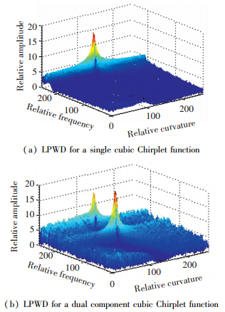
The LPWD for the cubic Chirplet function is shown in Fig. 1(a), and we can see that there is a peak in the (ω1, ω3) plane. The estimated value of γ0 could be achieved through the position of the peak.

|
Figure 1 LPWD of the simulated signal |
2) Multi-component Cubic Chirplet functions.
The two-component cubic Chirplet functions are considered, and the coefficients are shown in Table 2 as follows. Here, the signal length is 255, the sampling rate is supposed to be unity.
| Table 2 Parameters of the two-component cubic Chirplet functions |
The LPWD for the two-component cubic Chirplet functions is given in Fig. 1(b). It can be seen that there exist two peaks in the (ω1, ω3) plane, and the estimated value of γk could be achieved by the positions of the peaks associated with the CLEAN technique.
Remark 1 Here, the LPWD is selected as a tool to evaluate the coefficients of cubic Chirplet function, the cubic Chirplet function can detect the instantaneous frequencies of signal with multicomponent. Hence, it could be said that the LPWD is effective in identifying the instantaneous frequencies associated with the cubic Chirplet function.
3 ISAR Imaging Based on Cubic Chirplet Decom-position TechniqueFor radar imaging of ship target with complicated motions, the radar echo can be characterized as amplitude modulation and frequency modulation (AM-FM) signal with multicomponent. The ISAR images with good quality could be achieved through the estimated values of AM-FM signal coefficients and associated with the range instantaneous Doppler (RID) approach [18-21]. A good way to study the AM-FM signal is the cubic Chirplet decomposition. Hence, a novel approach for the cubic Chirplet decomposition through the LPWD approach is used during this part to generate the radar images of ship target with good quality.
3.1 ISAR Imaging ProcedureThe radar imaging procedure through the cubic Chirplet decomposition technique could be summarized as:
Step 1 Translation movement compensation, which can be referred in Ref.[22].
Step 2 Characterize the echo signals in a range cell as the integration of cubic Chirplet function, which has been shown in Eq.(3).
Step 3 Obtain the coefficients of each cubic Chirplet function through the cubic Chirplet decomposition technique.
Step 4 Generate the instantaneous ISAR images by the estimated parameters through the RID method.
3.2 Experimental ResultsThe simulated and real data experimental results are provided to verify the correctnesss of cubic Chirplet decomposition technique.
3.2.1 Simulated ISAR dataA set of simulated data of ship target with complicated motion in the sea environment is used to show the correctnesss of cubic Chirplet decomposition technique. The complicated motion includes the yaw, pitch and roll, and the target's movement is listed as[23]:
| $ \left\{ \begin{array}{l} {\theta _r}\left( t \right) = {Q_r}\sin \left( {{\mathit{\Omega }_r}t} \right)\\ {\theta _p}\left( t \right) = {Q_p}\sin \left( {{\mathit{\Omega }_p}t} \right)\\ {\theta _y}\left( t \right) = {Q_y}\sin \left( {{\mathit{\Omega }_y}t} \right) \end{array} \right. $ | (8) |
where Ωr, Ωp and Ωy denote the roll, pitch and yaw velocities, Qr, Qp and Qy are the radians amplitudes. The rotational movement for ship target is shown in Table 3.
| Table 3 Rotational movement for ship target |
The radar imaging model is shown in Fig. 2(a). It is supposed that the imaging radar locates on the coordinate origin O of the coordinate of
There are 66 scatterers in the ship, and the geometrical model is given in Fig. 2(b).

|
Figure 2 ISAR imaging geometry and target model |
We consider that the linear frequency modulation (LFM) signal is transmitted, the parameters for the radar system are shown as: the central frequency is fc=10 GHz, the bandwidth for the transmitted signal is B=400 MHz, the width of the pulse is Tp=20 μs, the frequency of sampling is fs=120 MHz, the pulse repetition frequency is PRF=625 Hz, the number of pulses is 1 024.
Remark 2 Here, we have to say that the "stretch" method could be selected to decrease the frequency of sampling for the simulated data. This can be implemented by the Dechirped technique with the reference signal, thus the signal's bandwidth can be decreased significantly. For the simulated data, the bandwidth through "stretch" technique could be calculated as ΔB=2B·ΔL/(Tp·c)≈18.7 MHz, here ΔL denotes the target size in range direction and ΔL≈140 m. Hence, it can be concluded that the frequency of sampling of 120 MHz will be suitable in the analysis.
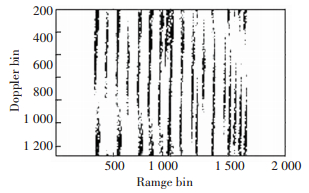
The ISAR image of ship target with conventional range Doppler (RD) algorithm is given in Fig. 3. We can conclude that the image is severely smeared for the sake of complicated motions.

|
Figure 3 Imaging result via RD algorithm |
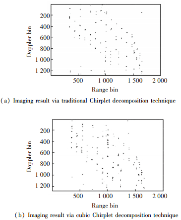
The imaging result via traditional Chirplet decom-position technique is shown in Fig. 4(a), where the Chirplet decomposition is implemented by the algorithm in Ref.[24]. Fig. 4(b) is the imaging result via cubic Chirplet decomposition technique. We can see from Fig. 4 that the quality of ISAR images is improved significantly by the comparison with the RD algorithm.

|
Figure 4 Imaging results for simulated data |
Then, the entropy is selected to evaluate the im-ages quality in Fig. 4, and the results are listed in Table 4. The entropy is defined in Ref.[25], and a smaller entropy corresponding to a better focused image. Here, the entropy is calculated by the normalization of the ISAR image, and thus it is a positive number in this paper.
| Table 4 Calculation results of entropy in Fig. 4 |
It can be concluded from Table 4 that the calcula-tion results of entropy in Fig. 4(b) is not as big as that in Fig. 4(a). This validates that the cubic Chirplet decomposition technique is more precise than the traditional Chirplet decomposition technique in the field of ISAR imaging.
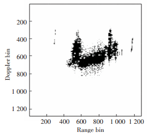
3.2.2 Real dataThe real data for ship is used to validate the correctness of cubic Chirplet decomposition technique. The radar transmits LFM signal, the transmitted signal bandwidth is B=400 MHz, the pulse repeat frequency (PRF) is PRF=500 Hz. The imaging result via RD algorithm is given in Fig. 5, and it is smeared severely.

|
Figure 5 Imaging result via RD algorithm |
Figs. 6(a)-(c) are the instantaneous imaging results via Chirplet decomposition technique at randomly selected time positions. We can see that the quality of images is improved compared with Fig. 5.

|
Figure 6 Imaging results via traditional Chirplet decomposition technique |
The imaging results via cubic Chirplet decomposition technique are given in Figs. 7(a)-(c), respectively.

|
Figure 7 Imaging results via cubic Chirplet decomposition technique |
The calculation results of entropy for the images in Fig. 6 and Fig. 7 are provided in Table 5. It is obvious that the quality of image of Fig. 6(b) is better.
Remark 3 In this paper, the complicated movement of the target can be interpreted as the nonlinear characteristics for the Doppler of the echo signal. This can be induced by the target's three-dimensional rotation or the angular velocity is time varying. Then, The RD technique is not appropriate to produce an ISAR image with high quality. Thus, we can use the RID method to obtain a high quality ISAR image.
4 ConclusionsThe cubic Chirplet decomposition via LPWD algorithm is introduced in this paper. By introducing a curvature parameter to the traditional Chirplet function, it can be seen that the cubic Chirplet function is more suitable to characterize the nonstationary signals of high nonlinear instantaneous frequency. This technique is adopted in ISAR imaging for the ship target with complicated motions, the quality of images will be improved by the comparison with the traditional Chirplet decomposition technique.
| [1] |
Mann S, Haykin S. The Chirplet transform: physical considerations.
IEEE Trans on SP, 1995, 43(11): 2745-2761.
DOI:10.1109/78.482123 ( 0) 0)
|
| [2] |
Greenberg J M, Wang Z S, Li J. New approaches for chirplet approximation.
IEEE Trans on SP, 2007, 55(2): 734-741.
DOI:10.1109/TSP.2006.885725 ( 0) 0)
|
| [3] |
Bultan A. A four-parameter atomic decomposition of chirplets.
IEEE Trans on SP, 1999, 47(3): 731-745.
DOI:10.1109/ICASSP.1997.604651 ( 0) 0)
|
| [4] |
Yin Q Y, Qian S, Feng A G. A fast refinement for adaptive Gaussian chirplet decomposition.
IEEE Trans on SP, 2002, 50(6): 1298-1306.
DOI:10.1109/TSP.2002.1003055 ( 0) 0)
|
| [5] |
Wang Y, Jiang Y C. ISAR imaging for three-dimensional rotation targets based on adaptive Chirplet decomposition.
Multidimensional Systems and Signal Processing, 2010, 21(1): 59-71.
DOI:10.1007/s11045-009-0087-2 ( 0) 0)
|
| [6] |
Lu Y F, Demirli R, Cardoso G, Saniie J. A successive parameter estimation algorithm for chirplet signal decomposition.
IEEE Trans. On Ultrasonics, Ferroelectrics, and Frequency Control, 2006, 53(11): 2121-2131.
DOI:10.1109/TUFFC.2006.152 ( 0) 0)
|
| [7] |
Weruaga L, Kepesi M. EM-driven stereo-like Gaussian chirplet mixture estimation.
International conference on Acoustics, Speech and Signal Processing, 2005: 473-476.
( 0) 0)
|
| [8] |
Li J, Ling H. Application of adaptive chirplet representation for ISAR feature extraction from targets with rotating parts.
IEE Proc.-Radar Sonar Navig, 2003, 150(4): 284-291.
DOI:10.1049/ip-rsn:20030729 ( 0) 0)
|
| [9] |
Luo X Q, He Q, Lv G Z, et al. ISAR Imaging of Multiple Targets Based on Adaptive Gaussian Chirplet Decomposition.
International Conference on Radar, 2006: 1-4.
( 0) 0)
|
| [10] |
Qian S, Chen D P. Adaptive chirplet based signal approximation.
IEEE Trans. on ASSP, 1998, 3(5): 1781-1784.
DOI:10.1109/ICASSP.1998.681805 ( 0) 0)
|
| [11] |
Yang Y, Zhang W M, Peng Z K, et al. Multicomponent signal analysis based on polynomial Chirplet transform.
IEEE Trans on Industrial Electronics, 2013, 60(9): 3948-3956.
DOI:10.1109/TIE.2012.2206331 ( 0) 0)
|
| [12] |
Yang Y, Peng Z K, Meng G, et al. Spline-kernelled Chirplet transform for the analysis of signals with time-varying frequency and its application.
IEEE Trans on Industrial Electronics, 2012, 59(3): 1612-1621.
DOI:10.1109/TIE.2011.2163376 ( 0) 0)
|
| [13] |
Angrisani L, Arco M D. A measurement method based on a modified version of the Chirplet transform for instantaneous frequency estimation.
IEEE Trans on Instrumentation and Measurement, 2002, 51(4): 704-711.
DOI:10.1109/TIM.2002.803295 ( 0) 0)
|
| [14] |
Stankovic L J. Local polynomial Wigner distribution.
Signal Processing, 1997, 59(1): 123-128.
DOI:10.1016/S0165-1684(97)00086-8 ( 0) 0)
|
| [15] |
Wang Y, Kang J, Jiang Y C. ISAR imaging of maneuvering target based on the local polynomial Wigner distribution and integrated high order ambiguity function for cubic phase signal model.
IEEE Journal of Selected Topics in Applied Earth Observations and Remote Sensing, 2014, 7(7): 2971-2991.
DOI:10.1109/JSTARS.2014.2301158 ( 0) 0)
|
| [16] |
Wang Y, Jiang Y C. Modified adaptive Chirplet decomposition with application in ISAR imaging of maneuvering targets. EURASIP Journal on Advances in Signal Processing, 2008. Article ID 456598.
( 0) 0)
|
| [17] |
Gough P T. A fast spectral estimation algorithm based on the FFT.
IEEE Trans on SP, 1994, 42(6): 1317-1322.
DOI:10.1109/78.286949 ( 0) 0)
|
| [18] |
Zheng J B, Su T, Zhu W T, et al. ISAR imaging of targets with complex motions based on the keystone time-chirp rate distribution.
IEEE Geoscience and Remote Sensing Letters, 2014, 11(7): 1275-1279.
DOI:10.1109/LGRS.2013.2291992 ( 0) 0)
|
| [19] |
Zheng J B, Su T, Zhang L, et al. ISAR imaging of targets with complex motion based on the chirp rate-quadratic chirp rate distribution.
IEEE Trans on GRS, 2014, 52(11): 7276-7289.
DOI:10.1109/TGRS.2014.2310474 ( 0) 0)
|
| [20] |
Chen V C, Miceli W J. Time-varying spectral analysis for radar imaging of maneuvering targets.
IEE Proc.-Radar Sonar Navig, 1998, 145(5): 262-268.
DOI:10.1049/ip-rsn:19982220 ( 0) 0)
|
| [21] |
Berizzi F, Mese E D, Diani M, et al. High-resolution ISAR imaging of maneuvering targets by means of the range instantaneous Doppler technique: Modeling and performance analysis.
IEEE Trans on Image Processing, 2001, 10(12): 1880-1890.
DOI:10.1109/83.974573 ( 0) 0)
|
| [22] |
Wang Y. Inverse synthetic aperture radar imaging of manoeuvring target based on range-instantaneous-Doppler and range-instantaneous-chirp-rate algorithms.
IET Proc.-Radar Sonar Navig, 2012, 6(9): 921-928.
DOI:10.1049/iet-rsn.2012.0091 ( 0) 0)
|
| [23] |
Gao Z Z, Li Y C, Xing M D, et al. ISAR imaging of manoeuvring targets with the range instantaneous chirp rate technique.
IET Proc.-Radar Sonar Navig, 2009, 3(5): 449-460.
DOI:10.1049/iet-rsn.2008.0082 ( 0) 0)
|
| [24] |
Wang Y, Jiang Y C. Approach for high resolution inverse synthetic aperture radar imaging of ship target with complex motion.
IET Signal Processing, 2013, 7(2): 146-157.
DOI:10.1049/iet-spr.2012.0080 ( 0) 0)
|
| [25] |
Wang J F, Liu X Z. Improved global range alignment for ISAR.
IEEE Trans on AES, 2007, 43(3): 1070-1075.
DOI:10.1109/TAES.2007.4383594 ( 0) 0)
|
 2017, Vol. 24


