2. Department of Mechanical Engineering, Kim Chaek University of Technology, Pyongyang, D. P. R of Korea
Semi-active control is one of the highest cost-effective and most application prospect control technology in the recent structural vibration control field, which is a perfect combination of the idea of active control and passive control strategy. In addition, the semi-active control can save control energy in the process of the control implementation and obtain the performance similar to active control. However, the control process of the semi-active control is stable and reliable.
In recent years, the application of the new intelligent material represented by MR fluid injected new vitality for the development of the semi-active control technology. Magneto-rheological (MR) fluid is a kind of the controllable fluids composed of the non-magnetic liquid, high magnetic and low hysteresis tiny magnetic particles, and the right amount of admixture. The admixture is used to guarantee the suspension stability of MR fluid. Under the action of magnetic field, MR fluids can change from the Newton fluid to the Bingham semi-solid for a moment (10 ms). Dampers made of this material can be used as the excellent semi-active control device, which feature big damping force, small energy consumption and easiness to control.
Magnetorheological fluid is a kind of intelligent material, it has controllability, reversibility and rapid response and other prominent advantages.
According to the operating mode, MR dampers can be classified into three types, i.e., shear mod[1], flow mod[2-4], squeeze mod[5-8].
So far, the reported MR dampers mostly used the flow mode due to its simple structure, large damping force and fast response. Spenser et al.[9] proposed MR damper to prevent earthquake and showed feasibility of the theoretical model. Cho et al.[10] designed a kind of MR damper using self-inductance, which did not depend on external energy. Hu et al.[11] proposed a new MR damper with improved displacement differential self-induced ability and experimentally evaluated the self-induced performance under static and dynamic working conditions. Guan et al.[12] designed a new compact self-powered MR damper featuring ball screw and rotating permanent magnet generators. Sohn et al.[13] designed a new MR damper with a piston bypass hole and verified the effectiveness of damping performance by numerical simulation and experiments.
On the one hand, in order to improve the control performance on MR damper, numerous control algorithms[14-17] have been also developed and realized for MR damper.
Compared with flow mode MR dampers, shear mode MR dampers are less studied. Most of shear mode dampers[18-19] have been used on rotary machine to isolate the unwanted vibration.
Each mode MR dampers have advantages and disadvantages for different application, so hybrid mode MR damper[20-21] was proposed. Liu[22] developed a novel MR damper with helix slotted plunger based on mechanical analysis on rheological characteristics of flow mod MR damper, through performance experiment and comparison with theoretical analysis, investigated the damping performance of the proposed MR damper.
However, dampers proposed by these researches can be used for the mechanical systems that require large damping force, so the dampers should possess big size of structure and use a lot of MR fluid.
Recently, with the requirements of miniaturized and generalized dampers, the small-sized and high-efficient MR dampers have attracted a lot of attention, which employ fewer expensive MR fluids and control the damping force with the strength of the vibration. In addition, with the development and application of the MR technology, various practical problems appeared. The strength and damping coefficient are two important factors, which affect the performance of the dampers for the engineering application.
The technical feature of this paper is to introduce a new shear mode MR damper structure, which features by simple structure, a small amount of MR fluid and convenience of fluid injection. The mathematical model of the proposed linear shear mode MR damper is constructed, and the numerical simulation of the damping force characteristics according to the change of current is investigated and compared with the experimental results. In addition, Liu[22] presented helix slot technology is applied to the proposed novel shear mod MR damper, and the effective of helix slot technology in shear mod MR damper are experimentally verified through comparison with the configuration of without helix slot piston. The remainder of this paper is organized as follows. The mechanical design for the shear mode MR damper is described in Section 2. In Section 3, the dynamic model is built and the damping characteristics are simulated. An experimental system is built up to test mechanical performance of the proposed shear mode MR damper in Section 4. The important conclusions are given in Section 5.
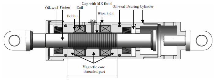
2 Linear Shear Mod MR Damper 2.1 Mechanical Design of the MR DamperThe MR damper consists of cylinder, piston, bearing, oil-seal device and MR fluid. The magnetic circuit is placed in the cylinder. The bearings are placed at the top and bottom of the magnetic circuit to support the piston. The oil-seal device is used to prevent leaking of the MR fluid. The MR fluid is full of the space between the piston and the magnetic circuit. The structure of the proposed shear mode MR damper is shown in Fig. 1. The main structural parameters of the proposed MR damper are shown in Table 1. Small amount of MR fluid (about 5.6 mL) need to be filled in the gap between the piston and the magnetic circuit. In other words, MR fluid is only in the ring gap channel. The prototype of the proposed MR damper is shown in Fig. 2.
|
Figure 1 Configuration of the proposed MR damper |
| Table 1 Main structural parameters of proposed MR damper |

|
Figure 2 Prototype of MR damper |
Most of the existing MR dampers are the flow mode dampers and hybrid dampers based on the flow mode and shear mode. Those dampers have MR fluid filled in cylinder, so a relatively large amount of expensive MR fluid need to be filled. The accumulator (gas chamber) or diaphragm is necessary to solve the problem of volume compensation, so the unnecessary damping force produced due to compressing gas is inescapable.
The proposed MR damper does not require any accumulators and diaphragms. MR fluid is closed by seal in the magnetic circuit. Thus, no problems of volume compensation need to be solved. The controllable damping force can be generated by using small amount of MR fluid.
In addition, the piston with helix slot engraved can improve the mechanical performance of the damper.
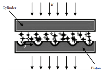
2.2 Helix Slotted PistonTo effectively increase the maximum values and damping coefficient of the damping force, the friction coefficient of two plates, especially the surface of the piston is increased. Engraving the serried and tiny helix slot on the piston can increase the friction coefficient, as shown in Fig. 3.
|
Figure 3 Parallel polar plate with helix slot |
Since the friction is a kind of contract force, it can be obtained by integral of friction stress over the friction surface. For damping channel in Fig. 3, the additional friction can be represented as:
| $ {F_s} = \int_A {{f_s}{\rm{d}}s} $ | (1) |
where A is the contact area, which can be determined by the shape and distribution of the helix slot.
Since the slot is designed to be spiral rather than annular, the reflux channel can be formed to prevent settling of the MR fluid and reduce the bubbles in the working status. To improve flow characteristics of the MR fluid in the slot, the helix angle can be increased, as shown in Fig. 4.

|
Figure 4 Types of helix slot |
Increasing helix angle leads to additional torque Ms around the axis of piston, which can be calculated by the equation as
| $ {M_s} = D'{F_s}\tan \left( \alpha \right)/2 $ | (2) |
where D′ is the pitch diameter of the helix slot, and α is the helix angle.
The generation of additional torque Ms leads to circulation of MR fluid in the helix slots channel. When applying magnetic field is weak or zero, the flow ability of MR fluid increases and the initial viscous force of the damper decreases, and MR fluid is forced to flow up and down in the state of reflux. In addition, when MR damper is working for long time, the temperature of MR fluid in the damper is increased and viscosity of the MR fluid is changed, and therefore the magnetic particles in the fluid are deposited. The helix slot channel makes MR fluid circle up and down follow helix slot by the additional torque, so the settlement of the magnetic particles is prevented.
The main design parameter of the helix slot configuration is depth of helix slot. The deeper the depth of slot the greater is its contact area, damping force is increased. But the increase of the slot depth means the increase of gap size, the excessive increase of slot depth is bad for rheological properties of MR fluid.
In order to ensure rheological properties of MR fluid, generally the gap of damping channel should be set as 0.7 mm-1.5 mm. So at the gap size of 0.9 mm, depth of helix slot should be shallow, to set as 0.3 mm-0.5 mm.
To compare the influence of helix slot on the mechanical performances of MR dampers, two types of pistons are presented and fabricated. They are the piston without helix slot and the piston with small helix angle slot, which possesses the helix pitch of 1 mm.
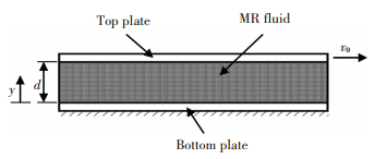
3 Mathematical Modeling and SimulationThe linear shear mode analysis of the mechanical model are based on the theory of parallel plate and Bingham-plastic model, the parallel plate model of a linear shear mode damper as shown in Fig. 5.
|
Figure 5 Parallel plate model of linear shear mode |
Due to the constant velocity linear motion of free microelements, the control equation of the liquid in the plate model is obtained by the force balance as follows:
| $ \frac{{{\rm{d}}\tau }}{{{\rm{d}}y}} = 0 $ | (3) |
where τ is the shear stress in the gap, and y is the coordinate.
The damping force of the linear shear mode MR damper can be formulated as:
| $ F = \tau Lb $ | (4) |
where L is the length of the plate, and b is the width of the plate.
The shear stress equation in the annular gap of the proposed MR damper by Bingham plastic model is calculated as follows:
| $ \tau \left( y \right) = \tau \left( y \right) + \frac{{\eta {v_0}}}{d} $ | (5) |
where τy is the yield stress; d is the gap; η is the fluid viscosity and v0 is the velocity of the top plate.
Then, substituting Eq.(5) into Eq.(4), the damping force F of the proposed damper can be obtained as follows:
| $ F = \tau Lb = bL\frac{\eta }{d}{v_0} + bL{\tau _y} = \frac{{\eta bL}}{d}\left( {1 + Bi} \right){v_0} $ | (6) |
where according to Ref.[21], the Bingham number Bi is described as
| $ Bi = \frac{{{\tau _y}d}}{{\eta {v_0}}} $ | (7) |
The equivalent damping of the proposed MR damper is defined as
| $ {C_{eq}} = \frac{F}{{{v_0}}} = \frac{{\eta bL}}{d}\left( {1 + Bi} \right) $ | (8) |
When Bingham number, Bi, is zero, the damping at the field-on status is obtained.
| $ C = \frac{{\eta bL}}{d} $ | (9) |
According Eqs.(8) and (9), the damping coefficient can be calculated as:
| $ \lambda = \frac{{{C_{eq}}}}{C} = 1 + Bi $ | (10) |
The damping coefficient, λ, is ratio of the force at the field-on status to the force at the field-off status, which is symbolic of the controllable damping force.
The damping force of the proposed liner shear mod MR damper obtained as follows:
| $ {F_{MR}} = bL\tau = 2{\rm{\pi }}R{L_e}\tau = 2{\rm{\pi }}R{L_e}\left( {{\tau _y}\left( B \right) + \frac{{\eta \dot x}}{d}} \right) $ | (11) |
| $ {F_{MR}} = 2{\rm{\pi }}R{L_e}\frac{{\eta \dot x}}{d} + 2{\rm{\pi }}R{L_e}{\tau _y}\left( B \right) $ | (12) |
where R is the diameter of the piston; Le is the effective length of the magnetic core and ẋ is the velocity of the piston.
During this study, Lord corporation's MRF-132DG was used, a field-independent plastic viscosity is η=0.112 Pa·s, in the case of the Bingham model, the post-yield viscosity of fluid is considered to be constant.
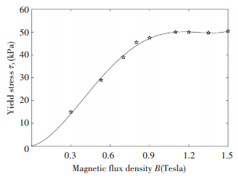
The approximate polynomial curve of the yield stress can be obtained using the least-squares curve fitting method to the fluid property specifications[23], as shown in Fig. 6 and the corresponding approximate polynomial of τy(B) is given as follows:
| $ \begin{array}{l} {\tau _y}\left( B \right) = 0.144 + 13.708B + 158.79{B^2} - 176.51{B^3} + 3\\ \;\;\;\;\;\;\;\;\;\;\;\;52.962{B^4} \end{array} $ | (13) |
|
Figure 6 Field-dependent yield stress of the MR fluid |
Finally, the damping force of the MR damper is obtained
| $ {F_d} = \left( {{F_{MR}} + {f_0}} \right){\mathop{\rm sgn}} \left( {\dot x} \right),\left( {\rm{N}} \right) $ | (14) |
where f0 is the friction force between piston and oil-seal.
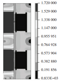
To calculate the saturation current, the MR damper was analyzed by finite element method using ANSYS/Emag software. The magnetic field was analyzed under current from 0 A to 1.5 A. As shown in Fig. 7, when the current exceeds I=1.4 A, the magnetic flux density reaches a saturation value of B=1.5T.
|
Figure 7 Magnetic flux density contour for the MR damper |
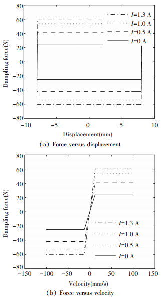
According to the parameters in Table 1, the damping force was simulated. MR damper was excited with a sinusoidal input signal with the frequency of 1.5 Hz and the displacement of ±8 mm. The damping force characteristics curves under different actuating current are shown in Fig. 8. When the saturation current is 1.3 A, the maximum damping force is 60 N and the minimum damping force is -60 N.
|
Figure 8 Damping force simulation |
4 Experiments of Mechanical Performance
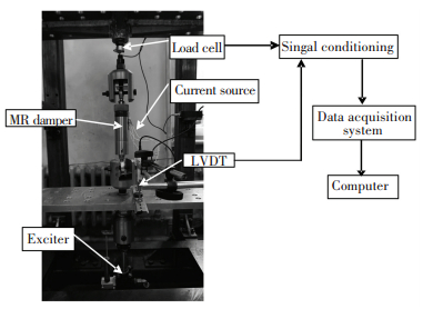
In order to evaluate the damping performance of the proposed MR damper, an experimental test was built up. The setup of the experiment is shown in Fig. 9. The experiment system consists of the MR damper, hydraulic servo testing machine, LVDT(linear variable differential transformer), force sensor, current source, signal conditioning device and data acquisition system. One end of the MR damper is in series with the force sensor by jig and fixed on the top of the test platform. The other end is connected with the moving platform which is controlled by the hydraulic servo testing machine. Signal conditioning device can supply power to the sensors and transform, filter the electrical signal.
|
Figure 9 Experimental setup for proposed MR damper testing |
The sinusoidal signal with the frequency of 1.5 Hz and the amplitude of 8mm is implemented on the two kinds of dampers by electro-hydraulic servo testing machine, respectively. The value of current is 0, 0.25 A, 0.5 A, 0.75 A, 1 A, 1.25 A and 1.5 A, respectively, which are the same with the simulation. The damping force-displacement curve can be measured. The velocity can be determined by the time differential of displacement. Fig. 10(a) shows the damper force-displacement hysteresis curve of the damper without helix slot, and Fig. 10(b) shows its force-velocity hysteresis curve. The results show that the damping force increases with increasing current. When the saturation current is 1.25 A, the maximum damping force reaches 62.5 N, the minimum damping force reaches -67.5 N, and the damping force change range is 130 N. As shown in Fig. 10(a), the damping force is almost constant value with the change of the displacement at the interval of operation. As shown in Fig. 10(b), the damping force is infinitesimally affected by damper velocity, when MR fluid begins to yield. The experimental results of the MR damper are agreed well to the simulation results.

|
Figure 10 Damping force test |
Fig. 11(a) shows the comparison between the force versus displacement hysteresis curves of dampers with helix slot and without helix slot, and Fig. 11(b) shows the comparison between the force versus velocity hysteresis curves of two types dampers.

|
Figure 11 Comparison of two damper characteristics (current I =1.25 A, frequency 1.5 Hz) |
The average values of positive damping forces of the two kind dampers in different cases are calculated and shown in Table 2. The results demonstrate that the initial viscous forces of two dampers are similar when the current is zero. If no applying current is imposed, the damping force of damper with helix slot is slightly smaller than damper without helix slot, because the helix slot increases the circulation of the MR fluid in the damper. When applying current is increased to 1 A, MR fluid is curing by the action of a magnetic field. When the applying current exceeds 1 A, MR fluid is gradually solidified and damping force of the damper with helix slot gets bigger, and the effect of helix slot is more obvious. And the damping force of the damper increases with the increase of pressure gradient and friction force. As the applying current continues to increase, the magnetic flux density reaches saturation state, as shown in Fig. 10, and MR fluid reaches maximum shear yield strength. When the applying current is 1.25 A, the damping coefficient of the damper without helix slot can reach λ=1.78, and the damper with helix slot can reach λ=2.67 because of improving the maximum damping force. As the applying current increases, the effectiveness of helix slot is more obvious, because curing degree of the MR body gets more with the increase of current and the contact force with the surface of the piston gets bigger. The damping force of the damper with helix slot is enhanced 20% in comparison with damper without helix slot.
| Table 2 Average values of positive damping forces of the two dampers in different cases |
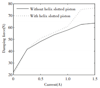
The current-damping force curves of the two types of dampers are shown in Fig. 12. Due to the reflux channel of helix slot, the initial viscous force of the damper is reduced. As the applying current and pressure increase, the effect of the friction gets more obvious. In addition, the maximum damping force also reaches its saturation state, when the magnetic field reaches the saturation state. However, since the helix slot provides additional interfacial friction, the maximum damping force of the damper with helix slot is still improved.
|
Figure 12 Current-damping force curves of the two types of dampers |
Since the helix slot produce friction on the contact surface, it can be similarly considered as the optimization of damping channel interface, which can be used to simulate the action of helix slot by modifying effective length Le of piston.
| $ {f_{MR}} = 2{\rm{\pi }}R{L_e}\frac{{\eta \dot x}}{d} + 2{\rm{\pi }}R\mu {L_e}{\tau _y}\left( B \right) $ | (15) |
where the first term of right side is viscous force and the second one is Coulomb force, and μ is the correction coefficient for piston effective length, which only exists in the Coulomb force part. The value of μ is associated with the form of helix slot. According to the analysis of the test results, μ=1.0-1.3.
5 ConclusionsThis paper proposes a novel type of linear shear mod MR damper, and through the analytical simulation and the test of the performance, the following conclusions are obtained:
1) The novel MR damper only needs a small amount of MR fluid and does not need gas chamber and diaphragm. So unnecessary damping force caused by compensation volume is avoidable.
2) By applying Bingham-plastic model to the proposed MR damper, the optimal design parameters can be deduced. The experimental results of the MR damper are agreed well to the simulation results.
3) In order to improve the mechanical performance of the MR damper, helix slot technology has been used to increase the friction between the MR fluid and damping channel interface and improve maximum output performance of the damper. With the increase of the magnetic flux density, the effect of the helix slot is more significant and the growth rate of maximum damping force can reach more than 20%.
4) The additional torque caused by the helix slot can generate the relative rotation between piston and magnetic core and increase reflux of the MR fluid in the damper, which can prevent the settlement of MR fluid and appearance of air bubbles.
| [1] |
Lou Z, Ervin R D, Filisko F E. A preliminary parametric study of electro-rheological dampers.
Journal of Fluids Engineering-Transactions of the ASME, 1994, 116(3): 570-576.
DOI:10.1115/1.2910315 ( 0) 0)
|
| [2] |
Wereley N M, Pang L. Nondimensional analysis of semi-active electrorheological and magnetorheological dampers using approximate parallel plate models.
Smart Material and Structures, 1998, 7(5): 732-743.
DOI:10.1088/0964-1726/7/5/015 ( 0) 0)
|
| [3] |
Choi Y T, Wereley N M. Comparative analysis of the time response of electro-rheological and magneto-rheological dampers using non-dimensional parameters.
Journal of Intelligent Material Systems and Structures, 2002, 13(7/8): 443-451.
( 0) 0)
|
| [4] |
Wereley N M, Lindler J, Rosenfeld N, et al. Biviscous damping behavior in electro-rheological shock absorbers.
Smart Material and Structures, 2004, 13(4): 743-752.
DOI:10.1088/0964-1726/13/4/012 ( 0) 0)
|
| [5] |
Stanway R, Sproston J L, Stevens N G. Non-linear modeling of an electro-rheological vibration damper.
Journal of Electrostatics, 1987, 20(2): 167-184.
DOI:10.1016/0304-3886(87)90056-8 ( 0) 0)
|
| [6] |
Williams S W, Rigby S G, Sproston J L, et al. Electr-orheological fluids applied to an automotive engine mount.
Journal of Non-Newtonian Fluid Mechanics, 1993, 47(6): 221-238.
DOI:10.1016/0377-0257(93)80052-D ( 0) 0)
|
| [7] |
Sims N D, Stanway R, Johnson A R. Vibration isolation using an MR damper in the squeeze-flow mode.
Smart Structures and Integrated Systems, Proc. SPIE. Bellingham WA :SPIE, 1999, 3668(5): 520-526.
( 0) 0)
|
| [8] |
Ahn Y K, Ha J Y, Kim Y H, et al. Dynamic chara-cteristics of squeeze-type mount using magneto-rheological fluid.
Proceedings of the Institution of Mechanical Engineers, Part K-Journal of Multi-body Dynamics, 2005, 219(1): 27-34.
DOI:10.1243/146441905X10005 ( 0) 0)
|
| [9] |
Jr Spencer B F, Dyke S J, Sain M K, et al. Pheno-menological model for a magneto-rheological damper.
Journal of Engineering Mechanics, ASCE, 1997, 123(3): 230-238.
DOI:10.1061/(ASCE)0733-9399(1997)123:3(230) ( 0) 0)
|
| [10] |
Cho S W, Jung H J, Lee I W. Smart passive system based on magneto-rheological damper.
Smart Material and Structures, 2005, 14(4): 707-714.
DOI:10.1088/0964-1726/14/4/029 ( 0) 0)
|
| [11] |
Hu Guoliang, Zhou Wei, Li Weihua. A new magnetorheological damper with improved displacement differential self-induced ability.
Smart Material and Structures, 2015, 24(8): 087001.
DOI:10.1088/0964-1726/24/8/087001 ( 0) 0)
|
| [12] |
Guan Xinchun, Huang Younghu, Li Hui, et al. A novel self-powered MR damper: theoretical and experimental analysis.
Smart Material and Structures, 2015, 24(10): 105033.
DOI:10.1088/0964-1726/24/10/105033 ( 0) 0)
|
| [13] |
Sohn J W, Oh J S, Choi S B. Design and novel type of a magnetorheological damper featuring piston bypass hole.
Smart Material and Structures, 2015, 24(3): 035013.
DOI:10.1088/0964-1726/24/3/035013 ( 0) 0)
|
| [14] |
Shen Y, Golnaraghi M F, Heppler G R. Semi-active vibration control schemes for suspension systems using magneto-rheological dampers.
Journal of Vibration Control, 2006, 12(1): 3-24.
DOI:10.1177/1077546306059853 ( 0) 0)
|
| [15] |
Chen H, Guo K H. Constrained H∞ control of active suspensions: an LMI approach.
IEEE Transaction on Control System Technology, 2005, 13(3): 412-421.
DOI:10.1109/TCST.2004.841661 ( 0) 0)
|
| [16] |
Crews J H, Mattson M G, Buckner G D. Multi-objective control optimization for semi-active vehicle suspensions.
Journal of Sound and Vibration, 2011, 330(23): 5502-5516.
DOI:10.1016/j.jsv.2011.05.036 ( 0) 0)
|
| [17] |
Phu D X, Shah K D, Choi S B. Design of a new adaptive fuzzy controller and its implementation for the damping force control of a magneto-rheological damper.
Smart Material and Structures, 2015, 24: 085012.
DOI:10.1088/0964-1726/24/8/085012 ( 0) 0)
|
| [18] |
Wereley N M, Cho J U, Choi Y T. Magnetorheological dampers in shear mode.
Smart Material and Structures, 2008, 17(1): 015022.
DOI:10.1088/0964-1726/17/01/015022 ( 0) 0)
|
| [19] |
Zhu C. Dynamic performance of a disk-type magnetor-heological fluid damper under AC excitation.
Journal of Intelligent Material Systems and Structures, 2005, 16(5): 449-461.
DOI:10.1177/1045389X05051700 ( 0) 0)
|
| [20] |
Brigley M, Choi Y T, Wereley N M. Experimental and theoretical development of multiple fluid mode magneto-rheological isolators.
Journal of Guidance Control and Dynamics, 2008, 31(3): 449-459.
DOI:10.2514/1.32969 ( 0) 0)
|
| [21] |
Yazid I I M, Mazian S A, Kikuchi T, et al. Design of magnetorheological damper with a combination of shear and squeeze modes.
Material and Design, 2014, 54: 87-95.
DOI:10.1016/j.matdes.2013.07.090 ( 0) 0)
|
| [22] |
Liu Jianjun.
New Magnetorheological Dampers and Its Intelligent Control Algorithms. Tianjin: Tianjin University, 2008: 50-56.
( 0) 0)
|
| [23] |
Lord Corporation MR fluid product bulletins online. http://www.rheonetic.com/fluidbegin.htm, 2003.
( 0) 0)
|
 2017, Vol. 24


