Pipes conveying fluid have been widely used on board, the dynamical behaviors of which are of great importance to the reliability of machinery and the safety of the corresponding working condition. The damage of pipes conveying fluid caused by vibration may lead to leak of oil and water. The dynamics of wet pipes has an obvious difference from that of empty pipes, fluid-structure interaction must be considered in the design of pipes conveying fluid. Researches in recent decades are mainly focused on the static reliability, dynamical behaviors and fluid-structure interaction of pipes conveying fluid.
Païdoussis[1-2] carried out a lot of researches on the dynamical characteristics of pipes conveying fluid, and obtained the basic vibration equation. It is shown that the inertial force term in the equation caused by the added mass of the fluid decreases the natural frequency of pipes. The equivalent flexural stiffness of pipes will decrease under the influence of centrifugal force. As the velocity of the fluid reaches critical velocity, the pipe will lose stability with divergence. The Coliolis force term may lead to negative damping effects and make the pipe flutter. Yuying Huang[3] gave the solution of the equation which was derived by Paidoussis and got the mode of wet pipes under simply supported boundary. M. Kheiri[4] studied the dynamics and stability of a wet pipe under different boundary. It is shown that an decrease in the stiffness makes the pipe more stable.Yang Chao[5] analyzed fluid-structure coupled vibration of wet pipes by using method of characteristics (MOC).14-function model was adopted in the numerical analysis and the MOC was improved to get higher numerical analysis precision. Li Baohui[6] studied the dynamics of the stepped wet pipes based on fluid-structure interaction. It is shown that the frequency of stepped wet pipes increased as its cross area decreasing. Kheiri et al[7] studied the dynamical equation of a typical flexible wet pipe based on Hamilton's principle. It is shown that the conclusion got by McIver[8] remains valid even on non-material volumes. Ryu[9] studied the dynamics of cantilevered wet pipes on elastic foundations. It is shown that the eigenvalue branches have an impact on the corresponding unstable modes of the pipe. The post-divergence behavior of extensible wet pipes was studied using the weakly nonlinear equations by Modarres-Sadeghi[10]. It is concluded that the amplitude of the resultant buckling decreases with decreasing flow. Birgersson[11] dealt with the dynamics of pipes according to Arnold-Warburton theory for thin shells. An efficient numerical solution to homogeneous random excitation is given in his study. Q. Ni et al.[12] analyzed the dynamics of wet pipes under different boundary conditions using differential transformation method (DTM). It is shown that differential transformation method is useful and efficiency in the dynamical analysis of wet pipes. Pittard and Blotter[13-14] studied the fluid-structure interaction based on Large Eddy Simulation models. The instantaneous fluctuations were computed in turbulent flow. It is shown that relationship between the standard deviation of the pressure and the flow rate is nearly quadratic. Wadham et al.[15-17] investigated the three-dimensional nonlinear dynamics of wet pipes under different boundary conditions. The equations of motion are presented in dimensionless form.
From the articles published, the damping of pipes and viscidity of fluid are usually neglected, for the reason that they are hard to be estimated with theoretical and numerical measures. And few experiments on the damping of wet pipes are found. On the other hand, in traditional computation, damping is always treated as fixed constant under all conditions, which causes discrepancy in prediction. At this point, the equation of motion for simply supported pipe is put out, taking the structural damping of pipes and viscidity of fluid into consideration. And the equation is also solved by using Galerkin's method. Modal identifications based on strain gauge test are carried out on both dry pipes and pipes conveying fluid. And variation of damping ratio is also deduced.
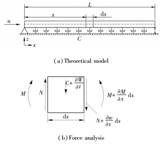
2 Theory 2.1 Differential Equation of MotionThe pipe conveying fluid in the article is modeled as a horizontal simply supported beam as shown in Fig. 1. For the sack of simplification, there are some assumptions:
|
Figure 1 Sketch of the model |
1) The fluid is incompressible and free from pulsation;
2) The flow has constant velocity;
3) The pipe is regarded as an Euler-Bernoulli beam;
4) The pipe is considered to have structural damping;
5) The damping caused by fluid is proportional to the vertical velocity.
The basic equation of motion for simply supported pipes, taking inertial force, centrifugal force, Coliolis force caused by the fluid into consideration is shown as Eq.(1).
| $ EI\frac{{{\partial ^4}w}}{{\partial {x^4}}} + {m_2}{u^2}\frac{{{\partial ^2}w}}{{\partial {x^2}}} + 2{m_2}u\frac{{{\partial ^2}w}}{{\partial x\partial t}} + \left( {{m_1} + {m_2}} \right)\frac{{{\partial ^2}w}}{{\partial {t^2}}} = 0 $ | (1) |
In which EI means the flexural rigidity and m1 means the mass per unit length of the pipe; u means the mean axial velocity and m2 means the mass per unit length of the fluid.
Taking structural damping of the pipe and viscidity of fluid into consideration, consider a part of the pipe of length dx, the vertical equilibrium equation is shown as Eq. (2) and the torque equilibrium equation as Eq.(3).
| $ - \frac{{\partial N}}{{\partial x}} - C\frac{{\partial w}}{{\partial t}} = {m_1}\frac{{{\partial ^2}w}}{{\partial {t^2}}} + {m_2}\frac{{{{\rm{d}}^2}w}}{{{\rm{d}}{t^2}}} $ | (2) |
| $ N = \frac{{\partial M}}{{\partial x}} $ | (3) |
In which N is the transverse shear force; w is the vertical deflection of the pipe; C is the equivalent damping factor of the fluid. M is the torque. The relationship between M and w is stated as follows:
| $ M = {E^ * }I\frac{{{\partial ^2}w}}{{\partial {x^2}}} $ | (4) |
In which E*I is the complex flexural rigidity of the pipe, where
| $ {E^ * } = E\left( {1 + i\eta } \right) $ | (5) |
In which η is the loss factor of the pipe. The velocity and acceleration of the fluid particle in vertical direction is shown as Eqs.(6) and (7).
| $ \frac{{{\rm{d}}w\left( {x,t} \right)}}{{{\rm{d}}t}} = \frac{{\partial w}}{{\partial x}}\frac{{{\rm{d}}x}}{{{\rm{d}}t}} + \frac{{\partial w}}{{\partial t}} = u\frac{{\partial w}}{{\partial x}} + \frac{{\partial w}}{{\partial t}} $ | (6) |
| $ \frac{{\rm{d}}}{{{\rm{d}}t}}\left[ {\frac{{{\rm{d}}w\left( {x,t} \right)}}{{{\rm{d}}t}}} \right] = {u^2}\frac{{{\partial ^2}w}}{{\partial {x^2}}} + 2u\frac{{{\partial ^2}w}}{{\partial x\partial t}} + \frac{{{\partial ^2}w}}{{\partial {t^2}}} $ | (7) |
Then the differential equation of motion can be obtained:
| $ \begin{array}{l} {E^ * }I\frac{{{\partial ^4}w}}{{\partial {x^4}}} + C\frac{{\partial w}}{{\partial t}} + {m_2}{u^2}\frac{{{\partial ^2}w}}{{\partial {x^2}}} + 2{m_2}u\frac{{{\partial ^2}w}}{{\partial x\partial t}} + \\ \;\;\;\;\;\;\;\;\;\left( {{m_1} + {m_2}} \right)\frac{{{\partial ^2}w}}{{\partial {t^2}}} = 0 \end{array} $ | (8) |
Then Eq.(8) can be written as Eq.(9), in which fej is the frequency of the pipe.
| $ EI\frac{{{\partial ^4}w}}{{\partial {x^4}}} + \frac{{\eta EI}}{{2{\rm{\pi }}{f_{\theta j}}}}\frac{{{\partial ^5}w}}{{\partial {x^4}\partial t}} + C\frac{{\partial w}}{{\partial t}} + {m_2}{u^2}\frac{{{\partial ^2}w}}{{\partial x\partial t}} + \left( {{m_1} + {m_2}} \right)\frac{{{\partial ^2}w}}{{\partial {t^2}}} = 0 $ | (9) |
The equation is solved with Galerkin's method. The potential function can be written as below:
| $ w\left( {x,t} \right) = \sum\limits_{j = 1}^N {{Y_j}\left( x \right){q_j}\left( t \right)} $ | (10) |
where Yj(x) is the simply supported beam eigenfunction. Once Eq.(10) is substituted into the equation of motion, the energy functional is obtained as below:
| $ \begin{array}{*{20}{c}} {\int_0^L {\left[ {EI\frac{{{\partial ^4}w}}{{\partial {x^4}}} + \frac{{\eta EI}}{{2{\rm{\pi }}{f_{\theta j}}}}\frac{{{\partial ^5}w}}{{\partial {x^4}\partial t}} + C\frac{{\partial w}}{{\partial t}} + {m_2}{u^2}\frac{{{\partial ^2}w}}{{\partial x\partial t}} + } \right.} }\\ {\left. {2{m_2}u\frac{{{\partial ^2}w}}{{\partial x\partial t}} + \left( {{m_1} + {m_2}} \right)\frac{{{\partial ^2}w}}{{\partial {t^2}}}} \right]{Y_j}\left( x \right){\rm{d}}x = 0} \end{array} $ |
where j=1, 2, …, N.
This equation can be simplified as follows:
| $ \left[ M \right]\left\{ {\ddot Q} \right\} + \left[ C \right]\left\{ {\dot Q} \right\} + \left[ M \right]\left\{ Q \right\} = \left\{ 0 \right\} $ |
where {Q} is shown that
| $ \left\{ Q \right\} = {\left\{ {{q_1},{q_2}, \cdots ,{q_N}} \right\}^{\rm{T}}} $ |
[M], [C] and [K] are the mass, damping and rigidity matrix respectively, in which the elements are shown as below:
| $ \begin{array}{l} \;\;\;\;\;\;\;\;\;\;\;\;\;\;\;{M_{jk}} = \int_0^L {\left( {{m_1} + {m_2}} \right){Y_k}\left( x \right){Y_j}\left( x \right){\rm{d}}x} \\ {C_{jk}} = \int_0^L {\frac{{\eta EI}}{{2{\rm{\pi }}{f_{\theta j}}}}Y_k^{\left( 4 \right)}\left( x \right){Y_j}\left( x \right){\rm{d}}x} + \int_0^L {2{m_2}u{{Y'}_k}\left( x \right){Y_j}\left( x \right){\rm{d}}x} \\ {K_{jk}} = \int_0^L {EIY_k^{\left( 4 \right)}\left( x \right){Y_j}\left( x \right){\rm{d}}x} + \int_0^L {{m_2}{u^2}{{Y''}_k}\left( x \right){Y_j}\left( x \right){\rm{d}}x} \end{array} $ |
Consider the first two order of the modal[18], when u=0, the frequency equation can be obtained:
| $ {s^2} + \left( {\eta {\beta ^2} + \frac{C}{{{m_1} + {m_2}}}} \right)s + {\left( {2{\rm{\pi }}{f_{ej}}} \right)^2} = 0 $ |
In which j=1, 2, and
| $ \beta = \sqrt {{m_1}/\left( {{m_1} + {m_2}} \right)} $ | (11) |
Then the frequency of the wet pipe can be obtained:
| $ {f_j} = {f_{ej}}\beta \sqrt {1 - {{\left( {\frac{{\eta \beta }}{2} + \frac{C}{{4{\rm{\pi }}\left( {{m_1} + {m_2}} \right)\beta {f_{ej}}}}} \right)}^2}} ,\left( {j = 1,2} \right) $ |
The damping ratio of the pipe conveying fluid is
| $ {\zeta _j} = {\zeta _{e{\rm{j}}}}\beta + \frac{C}{{4{\rm{\pi }}\left( {{m_1} + {m_2}} \right)\beta {f_{e{\rm{j}}}}}},\left( {j = 1,2} \right) $ |
In which ζej is the damping ratio of the dry pipe. Hence the equivalent damping factor of fluid can be obtained:
| $ C = 4{\rm{\pi }}\beta {f_{ej}}\left( {{m_1} + {m_2}} \right)\left( {{\zeta _j} - \beta {\zeta _{ej}}} \right),\left( {j = 1,2} \right) $ | (12) |
Numerical computation on a brass pipe whose geometrical and physical parameters are shown in Table 1 is carried out. There are some assumptions:
| Table 1 Pipe parameters used in the calculations |
1) The pipe is considered to have ideal simply supported boundary condition;
2) Fluid is equivalent as added mass and added damping;
3) The equivalent damping factor which is tested in the experiment is set as 0.021 for the dry pipe and 0.019 for the wet pipe.
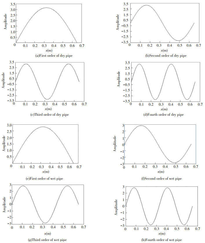
Tables 2-3 show the natural frequencies of the first 4 orders from the numerical computation under different conditions and the corresponding mode shapes are shown in Fig. 2. It is seen that the natural frequency of the wet pipe is smaller than that of the dry pipe, which indicates that fluid lead to the reduction in frequency. Structural damping also lead to the reduction in frequency especially in the high frequency and fluid induced damping have little impact on the natural frequencies. The mode shapes of the dry pipe and the wet pipe are almost the same except some differences in amplitude, which indicates that fluid has little impact on the mode shapes of the pipe.
| Table 2 Natural frequency of the first 4 orders(Dry pipe) |
| Table 3 Natural frequency of the first 4 orders(Wet pipe) |
|
Figure 2 Mode shapes of the first 4 orders |
4 Experiment 4.1 Testing Description
Model test under different conditions on a brass pipe, whose geometrical and physical parameters are shown in Table 1, is carried out to imitate the installation of pipe on board. The pipe is simply supported on the foundation with large inertia and rigidity to ensure ideal boundary condition as shown in Fig. 3. Strain gauges instead of accelerometers are arranged equidistantly to reduce the influence of added mass caused by the sensor. The pipe experienced free vibration under different initial deformation ranging from 50 με to 350 με, 50 με at intervals at the middle point and the response are recorded and analyzed. Modal identification is conducted referring to the methods introduced in Ref. [19], except that the transform function for bending displacement should be converted into those for strain. For an Euler-Bernoulli beam under flexural deformation, the relationship between displacement and strain can be written as follows:
| $ \varepsilon = h\frac{{{\partial ^2}w}}{{\partial {x^2}}} $ |
In which ε is the magnitude of the strain; h is the distance to the center axis of the beam. Thus the strain transform function can be written in the forms of displacement transform function as follows:
| $ {H_\varepsilon }\left( w \right) = - \left( {c_{\rm{B}}^2/{\omega ^2}R} \right){H_s}\left( w \right) $ |
In which Hε is the strain transform function; Hs is the displacement transform function; cB is the phase velocity of the bending wave in the beam; ω is the radiation frequency.

|
Figure 3 Testing sample |
4.2 Results and Discussion
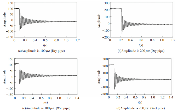
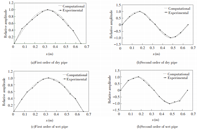
Fig. 4 shows time waveforms being tested from some representative measuring points. Then natural frequency and damping ratio are obtained with FFT and half-power bandwidth method. Fig. 5 shows the spectral result converted from the time waveforms comparing with the computational results from Eqs.(1) and (9). It is seen that the frequency decreases as the pipe is filled with water. Tables 4-5 lists the natural frequencies of the first 3 orders from the experiment and computation. It is seen that natural frequencies from computation match well with those from testing especially for the first and the second order, which validates Eq.(9), and the discrepancy increases with the frequency. It is more accurate as damping is considered. Fig. 6 shows the mode shapes of the first 2 orders being tested under different conditions. It is seen that the mode shapes of the dry pipe and the wet pipe are almost the same, which validates the numerical results.
|
Figure 4 Time waveform |

|
Figure 5 Spectral results |
| Table 4 Natural frequency of pipes under different conditions (Dry pipe) |
| Table 5 Natural frequency of pipes under different conditions (Wet pipe) |
|
Figure 6 Mode shapes being tested |
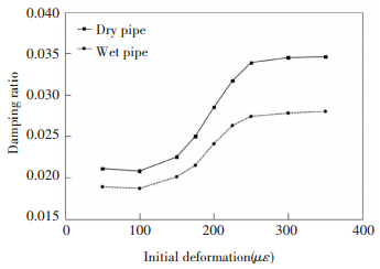
Fig. 7 shows the damping ratio of the first order varying with initial deformation. It is seen that the damping ratio of the wet pipe is smaller than that of the dry pipe, which indicates that fluid in the pipe leads to reduction of damping ratio under the same initial deformation. Damping ratio increases with the initial deformation generally, but it varies little under small deformation and large deformation. The curve increases with initial deformation almost linearly between 150 and 250 με (transition section), which can be fitted as follows:
| $ {\zeta _{ej}} = \left\{ \begin{array}{l} {\alpha _1},\;\;\;\;\;\;\;\;\;\;\;\;\;\;\;\;\;\;\;\;\;\;\;\;\;\;\;\varepsilon \le {\varepsilon _1}\\ \frac{{{\alpha _2} - {\alpha _1}}}{{{\varepsilon _2} - {\varepsilon _1}}}\left( {\varepsilon - {\varepsilon _1}} \right) + {\alpha _1},\;\;{\varepsilon _1} < \varepsilon \le {\varepsilon _2}\\ {\alpha _2},\;\;\;\;\;\;\;\;\;\;\;\;\;\;\;\;\;\;\;\;\;\;\;\;\;\;\;\varepsilon > {\varepsilon _2} \end{array} \right. $ |
| $ {\zeta _j} = \left\{ \begin{array}{l} {\alpha _3},\;\;\;\;\;\;\;\;\;\;\;\;\;\;\;\;\;\;\;\;\;\;\;\;\;\;\;\varepsilon < {\varepsilon _1}\\ \frac{{{\alpha _4} - {\alpha _3}}}{{{\varepsilon _2} - {\varepsilon _1}}}\left( {\varepsilon - {\varepsilon _1}} \right) + {\alpha _3},\;\;{\varepsilon _1} < \varepsilon \le {\varepsilon _2}\\ {\alpha _4},\;\;\;\;\;\;\;\;\;\;\;\;\;\;\;\;\;\;\;\;\;\;\;\;\;\;\;\varepsilon > {\varepsilon _2} \end{array} \right. $ |
|
Figure 7 Damping ratio under different initial deformation |
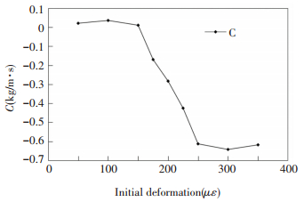
In which α1, α2, α3, α4 are constants related with the material of the pipe and the fluid; ε1 and ε2 are the boundaries of the transition section, between which the damping ratio of both the dry pipe and the wet pipe varies linearly with initial deformation. The relationship between α1 and α3 is obtained from the experimental result: α3/α1≈β. In which β is defined as Eq.(18), which indicates that only added mass of the fluid contributes to the changing of damping ratio as the pipe is filled with water under small deformation. Fig. 8 shows the equivalent damping factor C of the first order computed with Eq.(12), according to the damping ratio tested. It is seen from Fig. 8 that the calculated equivalent damping factor C is negative and decreases under large initial deformation. In traditional analysis, the effect of water is mainly treated as a kind of viscous damping. In practice, the rigidity of water can be neglected and water provides almost no damping, but the inertia of water will reduce the attenuation of pipe vibration, as the pipe experiences vibration under large deformation, which leads to the negative equivalent damping factor C.
|
Figure 8 Equivalent damping factor C under different initial deformation |
5 Conclusions
In this paper, the equation of motion for simply supported pipe is deduced, taking the structural damping of pipes and viscidity of fluid into consideration. And the theoretical model is validated with an experiment. It is concluded from the comparison of the computational and experimental results that:
1) The added mass caused by the fluid and the damping of the pipe both cause the decrease in frequency, to which the added mass contribute the most. The impact of the damping on the natural frequency of pipes conveying fluid increases with the frequency.
2) Fluid has little impact on the mode shapes of the pipe.
3) Damping ratio of pipes conveying fluid is smaller than that of the dry pipe. And the damping ratio depends greatly on the initial deformation. Fluid has little impact on the damping of the pipe conveying fluid under small deformation, but it leads to negative damping effects under large deformation.
| [1] |
Païdoussis M P.
Fluid-structure interactions: Slender structures and Axial Flow. New York: Academic Press, 1998.
( 0) 0)
|
| [2] |
Païdoussis M P.
Fluid-structure Interactions: Slender Structures and Axial Flow. Amsterdam: Elsevier, 2004.
( 0) 0)
|
| [3] |
Huang Yuying.
Analysis on Structure Vibration. Wuhan: Huazhong University of Science and Technology, 1988.
( 0) 0)
|
| [4] |
Kheiri M, Païdoussis M P, Costa Del Pozo G, et al. Dynamics of a pipe conveying fluid flexibly restrained at the ends.
Journal of Fluids and Structures, 2014(49): 360-385.
DOI:10.1016/j.jfluidstructs.2013.11.023 ( 0) 0)
|
| [5] |
Yang Chao, Fan Shijuan. Numerical analysis of fluid-structure coupled vibration of fluid-conveying Pipe.
Journal of Vibration and Shock, 2009, 38(6): 56-59.
( 0) 0)
|
| [6] |
Li Baohui, Gao Xingshan. Fluid-structure interaction characteristic analysis of stepped pipe conveying fluid.
Mechanical Science and Technology for Aerospace Engineering, 2011, 30(12): 2056-2060.
( 0) 0)
|
| [7] |
Kheiri M, Païdoussis M P. On the use of generalized Hamilton's principle for the derivation of the equation of motion of a pipe conveying fluid.
Journal of Fluids and Structures, 2014(50): 18-24.
DOI:10.1016/j.jfluidstructs.2014.06.007 ( 0) 0)
|
| [8] |
McIver D B. Hamilton's principle for systems of changing mass.
Journal of Engineering Mathematics, 1973(7): 249-261.
( 0) 0)
|
| [9] |
Ryu B J, Ryu S U, Kim G H, et al. Vibration and dynamic stability of pipes conveying fluid on elastic foundations.
KSME International Journal, 2004, 18(12): 2148-2157.
DOI:10.1007/BF02990219 ( 0) 0)
|
| [10] |
Modarres-Sadeghi Y, Païdoussis M P. Nonlinear dynamics of extensible fluid-conveying pipes, supported at both ends.
Journal of Fluids and Structures, 2009(25): 535-543.
( 0) 0)
|
| [11] |
Birgersson F, Finnvedena S, Robertb G. Modelling turbulence-induced vibration of pipes with a spectral finite element method.
Journal of Sound and Vibration, 2004(278): 749-772.
DOI:10.1016/j.jsv.2003.10.024 ( 0) 0)
|
| [12] |
Ni Q, Zhang Z L, Wang L. Application of the differential transformation method to vibration analysis of pipes conveying fluid.
Applied Mathematics and Computation, 2011(217): 7028-7038.
DOI:10.1016/j.amc.2011.01.116 ( 0) 0)
|
| [13] |
Pittard M T, Evans R P, Maynes R D, et al. Experimental and numerical investigation of turbulent flow induced pipe vibration in fully developed flow.
Review of Scientific Instruments, 2004, 75(7): 2393-2401.
DOI:10.1063/1.1763256 ( 0) 0)
|
| [14] |
Pittard M T, Blotter J D. Numerical modeling of LES based turbulent flow induced vibration. Proceedings of ASME'03, 2003 International Mechanical Engineering Congress and Exposition. Washington, 2003.
( 0) 0)
|
| [15] |
Wadham-Gagnon M, Paidoussis M P, Semler C. Dynamics of cantilevered pipes conveying fluid. Part1: Nonlinear equations of three-dimensional motion.
Journal of Fluids and Structures, 2007(23): 545-567.
( 0) 0)
|
| [16] |
Paidoussis M P, Wadham-Gagnon M, Semler C, et al. Dynamics of cantilevered pipes conveying fluid. Part2: Dynamics of the system with intermediate spring support.
Journal of Fluids and Structures, 2007(23): 569-587.
( 0) 0)
|
| [17] |
Modarres-Sadeghi Y, Wadham-Gagnon M, Semler C, et al. Dynamics of cantilevered pipes conveying fluid. Part3: Three-dimensional dynamics in the presence of an end-mass.
Journal of Fluids and Structures, 2007(23): 589-603.
( 0) 0)
|
| [18] |
Gregory R W, Paidoussis M P. Unstable oscillation of tubular cantilevers conveying fluid.
Proceedings of the Royal Society, 1966, A293: 512-542.
( 0) 0)
|
| [19] |
Liu Changqing, Che Chidong, Shen Xiaohan. Experimental and numerical study on vibration of the full-revolving propulsion ship stern.
China Ocean Engineering, 2015, 29(1): 33-48.
DOI:10.1007/s13344-015-0003-5 ( 0) 0)
|
 2017, Vol. 24


