In general, passive noise control is the most effective at middle and high frequencies and ineffective at low frequencies[1]. Furthermore, the mass of the primary structure must be increased, which augments the analysis difficulty and the other question should emerge for the structure with light mass and high speed. With the development of science and technology, active absorption has been of importance to men. So active noise control is the most effective and has the advantages of fine system, light mass and easy control. With the development of update controlling technology, active absorption is becoming a research hotspot.
Active noise control (ANC) is attained by introducing a canceling "anti-noise" wave of the same amplitude and opposite phase using a secondary source[2], which is posed by Paul L[2]. Early work on ANC used analog techniques. Now much work on ANC has been published, adaptive feed forward control is the most popular and successful approach used in ANC. Feed forward control involves feeding a signal related to the disturbance input (called the primary noise) into the controller which then generates a signal to drive a speaker in such a way as to cancel the disturbance. This signal related to the primary noise is called the reference signal[3-8]. Results on many successful feed forward ANC systems have been published. However, the major limitations of ANC systems should be noted. First, large secondary sources are needed in ANC. Second, other noise would be emerged with the secondary source. Third, the transducer, controller and actuator must be out of the structure of ANC so that the structure system is large, large additional mass, high cost, uneconomical function and the acoustic characteristic are changed[9-19]. In order to overcome the shortcomings above mentioned, active absorption is proposed. Furthermore, in some special situation, not only active absorption, but also active isolation are considered. Thus, in this paper, a new active absorption and active isolation method based on piezoelectric ceramics is proposed.
Piezoelectric ceramic can be used as the main material of transducer, energy exchanger, arrester etc. and used in the control system for its excellent mechanics and electric coupling performance. Some researchers have researched the sound and electricity characteristic of the piezoelectric ceramic, which is not applied in active absorption[20-21] yet. In this paper, two piezoelectric ceramics are applied as the absorption and isolation materials in active absorption and active isolation, two equal distance PVDF are placed in the front of the two piezoelectric ceramics in order to measure the incidence plane wave and the reflected wave and one piece of PVDF is placed on the back of the two piezoelectric ceramics in order to measure the isolation value. Voltage is applied on the piezoelectric ceramics in order to make the reflected wave and the transmitted wave zero using the adaptive controlling. At last, an experiment is carried out with different frequency plane wave and good absorption and isolation effect is attained, the experiment results denote that the theory is correct and practical.
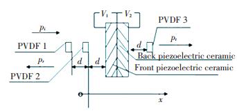
2 Theory of Active Absorption and Active IsolationThe arrangement of three pieces of PVDF and two materials are shown in Fig. 1.
|
Figure 1 The arrangement of three pieces of PVDF and two piezoelectric ceramics |
In Fig. 1, the incidence sound pressure is pi(t), three pieces of PVDF which take the role of microphones and front piezoelectric ceramic are arranged with the same distance. V1 and V2 are used at the piezoelectric ceramics.
2.1 Measurement Theory of the Incident and Reflection WaveThe incidence and reflection sound wave can be expressed as:
| $ \begin{array}{l} {p_i}\left( {x,t} \right) = {p_i}\exp \left( {{\rm{j}}\left( {\omega t - kx} \right)} \right)\\ {p_r}\left( {x,t} \right) = {p_r}\exp \left( {{\rm{j}}\left( {\omega t + kx} \right)} \right) \end{array} $ |
where k represents wave number and ω represents frequency of the sound wave.
When a force p is pressed on the surface of PVDF, then a voltage V is coming into being on the surface of the PVDF. The relation between the force p and the voltage V is [15]
| $ p = \frac{{{e_{33}}{Z_o}}}{{{t_p}\left( {{Z_o} + {Z_p}} \right)}}V = \frac{V}{S} $ |
where e33 is coupling constant of the PVDF, Zo is characteristic impedance of the air, Zp is characteristic impedance of the PVDF, tp is thickness of the PVDF. The voltage signal of PVDF 1 and PVDF 2 is
| $ \begin{array}{*{20}{c}} {{V_1}\left( t \right) = {V_i}\left( {0,t} \right) + {V_r}\left( {0,t} \right)}\\ {{V_2}\left( t \right) = {V_i}\left( {d,t} \right) + {V_r}\left( {d,t} \right) = {V_i}\left( {0,t + \tau } \right) + {V_r}\left( {0,t - \tau } \right)} \end{array} $ |
where τ is propagation time between the PVDF 1 and PVDF 2, τ=d/c, c is the propagation velocity of the wave in the air. If the voltage V1(t) is delayed by τ, then V1τ(t) is gotten as follows:
| $ {V_{1\tau }}\left( t \right) = {V_1}\left( {t - \tau } \right) = {V_i}\left( {0,t - \tau } \right) + {V_r}\left( {0,t - \tau } \right) $ |
Voltage signal V3(t) is defined as:
| $ {V_3}\left( t \right) = {V_{1\tau }} - {V_2} = {V_i}\left( {0,t - \tau } \right) - {V_i}\left( {0,t + \tau } \right) $ |
If the signal V3(t) is delayed by τ, then the signal V5(t) is gotten:
| $ \begin{array}{*{20}{c}} {{V_5}\left( t \right) = {V_3}\left( {t - \tau } \right) = {V_i}\left( {0,t - 2\tau } \right) - {V_i}\left( {0,t} \right) = }\\ {2{V_i}\left( {0,t} \right){e^{ - {\rm{j}}\left( {\frac{{\rm{\pi }}}{2} + \omega \tau } \right)}}\sin \omega \tau } \end{array} $ | (1) |
If the voltage V2(t) is delayed by τ, then the following equation is gotten:
| $ {V_{2\tau }}\left( t \right) = {V_2}\left( {t - \tau } \right) = {V_i}\left( {0,t} \right) + {V_r}\left( {0,t - 2\tau } \right) $ |
Voltage signal V4(t) is defined as:
| $ \begin{array}{l} {V_4}\left( t \right) = {V_{2r}} - {V_1} = {V_r}\left( {0,t - 2\tau } \right) - {V_r}\left( {0,t} \right) = \\ \;\;\;\;\;\;\;\;\;\;\;2{V_r}\left( {0,t} \right){e^{ - {\rm{j}}\left( {\frac{{\rm{\pi }}}{2} + \omega \tau } \right)}}\sin \omega \tau \end{array} $ | (2) |
According to the Eq.(1) and Eq.(2), the following equations can be attained:
| $ {{V'}_4} = - {V_4} + {{V'}_4}{e^{ - 2{\rm{j}}\omega \tau }} = {V_r}\left( {0,t} \right) $ | (3) |
| $ {{V'}_5} = - {V_5} + {{V'}_5}{e^{ - 2{\rm{j}}\omega \tau }} = {V_i}\left( {0,t} \right) $ | (4) |
The incident and reflection sound pressure can be gotten according to the Eq.(3) and Eq.(4),
| $ \begin{array}{l} {p_r}\left( {0,t} \right) = S{{V'}_4} = S{V_r}\left( {0,t} \right)\\ {p_i}\left( {0,t} \right) = S{{V'}_5} = S{V_i}\left( {0,t} \right) \end{array} $ |
The signal pr(0, t) is reflection sound pressure of PVDF 1, the reflection sound pressure in the place of the front piezoelectric ceramic is
| $ {p_r} = {p_r}\left( {2d,t} \right) = \exp \left( {{\rm{j}}2kd} \right){p_r}\left( {0,t} \right) $ |
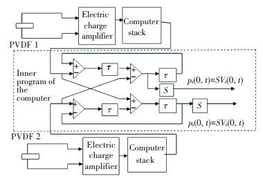
The principle of measuring the incidence and reflection sound pressure by two pieces of PVDF is shown in Fig. 2.
|
Figure 2 The principle of measuring the incidence and reflection sound pressure |
2.2 Principle of Measuring Absorption Coefficient by PVDF
The voltage VM at the middle point M between the PVDF 1 and PVDF 2 is
| $ {V_M} = S\left( {{p_{2i}}{e^{\frac{{{\rm{j}}kd}}{2}}} + {p_{2r}}{e^{ - \frac{{{\rm{j}}kd}}{2}}}} \right) $ | (5) |
| $ {p_1} + {p_2} = \frac{{{V_1} + {V_2}}}{S} = {p_{2i}}\left( {1 + {e^{{\rm{j}}kd}}} \right) + {p_{2r}}\left( {1 + {e^{ - {\rm{j}}kd}}} \right) $ | (6) |
where p1 and p2 are sound pressure at PVDF 1 and PVDF 2 respectively, p2i and p2r are incidence and reflection sound pressure at PVDF 2.
If kL1 is very small, the following equations are attained:
| $ {e^{ - \frac{{{\rm{j}}kd}}{2}}} \approx \frac{1}{2} + \frac{1}{2}{e^{ - {\rm{j}}kd}} $ | (7) |
| $ {e^{\frac{{{\rm{j}}kd}}{2}}} \approx \frac{1}{2} + \frac{1}{2}{e^{{\rm{j}}kd}} $ | (8) |
According to the Eq.(5) to Eq.(8), the following equation can be attained:
| $ {p_M} = \frac{{{V_M}}}{S} = \frac{{{V_A} + {V_B}}}{{2S}} $ | (9) |
The vibration velocity vM at point M is
| $ {v_M} = - \frac{{\partial p}}{{{\rm{j}}\omega {\rho _0}\partial r}} $ | (10) |
If the distance between PVDF 2 and the point M is very small, the Eq.(10) is
| $ {v_M} = - \frac{{\partial p}}{{{\rm{j}}\omega {\rho _0}\partial r}} = \frac{{2\left( {{V_B} - {V_M}} \right)}}{{{\rm{j}}Sd\omega {\rho _0}}} $ | (11) |
Leading the Eq.(9) into the Eq.(11), we can get:
| $ {v_M} = \frac{{{p_2} - {p_1}}}{{{\rm{j}}{L_1}\omega {\rho _0}}} = \frac{{{V_B} - {V_A}}}{{{\rm{j}}Sd\omega {\rho _0}}} $ |
The impedance ZM at the point M is
| $ {Z_M} = \frac{{{\rm{j}}d\omega {\rho _0}\left( {{V_B} + {V_A}} \right)}}{{2\left( {{V_B} - {V_A}} \right)}} $ |
The relation between the impedance at point M and surface impedance Z is
| $ Z = \frac{{{Z_M} - {\rm{j}}{\rho _0}{c_0}\tan \left( {\omega \frac{{3d}}{2}/{c_0}} \right)}}{{{\rho _0}{c_0} - {\rm{j}}{Z_M}\tan \left( {\omega \frac{{3d}}{2}/{c_0}} \right)}} $ |
The reflection coefficient R of the sound pressure is
| $ R = \frac{{Z - {\rho _0}{c_0}}}{{Z + {\rho _0}{c_0}}} $ |
Then, the absorption coefficient α is
| $ \alpha = 1 - {\left| R \right|^2} $ |
If the voltage of the PVDF 3 is VC, the sound pressure pt of the right surface of the second piezoelectric ceramic and the sound pressure transmission coefficient tp are
| $ \begin{array}{*{20}{c}} {{p_t} = \frac{{{V_C}{e^{{\rm{j}}kd}}}}{S}}\\ {{t_p} = \frac{{{p_t}}}{{{p_i}}} = \frac{{{\rm{j}}2\sin kd}}{{{V_A} - {V_B}{e^{ - {\rm{j}}kd}}}}{V_C}{e^{{\rm{j}}2kd}}} \end{array} $ |
The transmission value TL of the piezoelectric ceramic according to the sound pressure transmission coefficient is
| $ TL = - 20\log \left| {\frac{{{p_t}}}{{{p_i}}}} \right| = - 20\log \left| {\frac{{{\rm{j}}2\sin kd}}{{{V_A} - {V_B}{e^{ - {\rm{j}}kd}}}}{V_C}{e^{{\rm{j}}2kd}}} \right| $ |
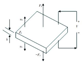
The structure of the piezoelectric ceramic is shown in Fig. 3.
|
Figure 3 Structure of the piezoelectric ceramic |
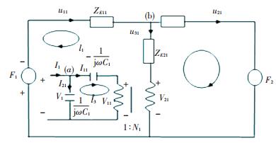
In the Fig. 3, b is the thickness of the piezoelectric ceramic; u1 and u2 are the vibration velocity in the direction of thickness; F1 and F2 are force press on the piezoelectric ceramic; V is the voltage. According to the structure of the piezoelectric ceramic, the equivalent circuit figuration of the front piezoelectric ceramic is attained, as shown in Fig. 4[14-15].
|
Figure 4 The equivalent circuit figuration of the front piezoelectric ceramic |
In the Fig. 4, ZE11=jρ1C1tDtan(k1t1/2), ZE21=(-jρ1C1tD)/sin k1t1, C1=ε133S/t1, N1=e133/t1, and t1, ρ1, C1tD, ε133S, e133 represent the front piezoelectric ceramic's thickness, density, elastic coefficient, dielectric constant and coupling constant respectively. The following equations can be derived according to the electro circuit theory:
| $ {F_1} = - \left( {{Z_{E11}} + {Z_{E21}}} \right){u_{11}} + {Z_{E21}}{u_{21}} - \frac{{{N_1}}}{{{\rm{j}}\omega {C_1}}}{I_1} $ |
| $ {F_2} = - \left( {{Z_{E11}} + {Z_{E21}}} \right){u_{21}} + {Z_{E21}}{u_{11}} + \frac{{{N_1}}}{{{\rm{j}}\omega {C_1}}}{I_1} $ |
| $ {V_1} = \frac{{{N_1}}}{{{\rm{j}}\omega {C_1}}}{u_{11}} - \frac{{{N_1}}}{{{\rm{j}}\omega {C_1}}}{u_{21}} + \frac{1}{{{\rm{j}}\omega {C_1}}}{I_1} $ |
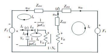
The equivalent circuit figuration of the back piezoelectric ceramic is shown in the Fig. 5[14-15].
|
Figure 5 The equivalent circuit figuration of the back piezoelectric ceramic |
In the Fig. 5, t2, ρ2, C2tD, ε233S, e233 represent the back piezoelectric ceramic's thickness, density, elastic coefficient, dielectric constant and coupling constant respectively, and
| $ {Z_{E12}} = {\rm{j}}{\rho _2}C_{2t}^D\tan \frac{{{k_2}{t_2}}}{2},{Z_{E22}} = \frac{{ - {\rm{j}}{\rho _2}C_{2t}^D}}{{\sin {k_2}{t_2}}} $ |
| $ {C_2} = \frac{{\varepsilon _{233}^S}}{{{t_2}}},{N_2} = \frac{{{e_{233}}}}{{{t_2}}} $ |
| $ {F_2} = - \left( {{Z_{E12}} + {Z_{E22}}} \right){u_{12}} + {Z_{E22}}{u_{22}} - \frac{{{N_2}}}{{{\rm{j}}\omega {C_2}}}{I_2} $ |
| $ {F_2} = - \left( {{Z_{E11}} + {Z_{E21}}} \right){u_{21}} + {Z_{E21}}{u_{11}} + \frac{{{N_1}}}{{{\rm{j}}\omega {C_1}}}{I_1} $ |
| $ {V_2} = \frac{{{N_2}}}{{{\rm{j}}\omega {C_2}}}{u_{12}} - \frac{{{N_2}}}{{{\rm{j}}\omega {C_2}}}{u_{22}} + \frac{1}{{{\rm{j}}\omega {C_2}}}{I_2} $ |
The reflected sound pressure pr, velocity u11 and the transmission sound pressure pt, velocity u21 satisfy the following relations:
| $ \begin{array}{l} {F_1} = \left( {{P_i} + {P_{\rm{r}}}} \right){A_1} = {P_i}{A_1}\\ {F_3} = {P_{\rm{t}}}{A_2} = 0\\ \frac{{{p_i} - {p_{\rm{r}}}}}{{{Z_1}}} = \frac{{{p_i}}}{{{Z_1}}} = {u_{12}}\\ \frac{{ - {p_{\rm{t}}}}}{{{Z_1}}} = {u_{22}} = 0 \end{array} $ |
where Z1 is characteristic impedance of the air, A2 is section area of the back piezoelectric ceramic. According to the above equations, the following equations are attained:
| $ {V_1} = \frac{{\left[ {{p_i} - \frac{{{p_i}}}{{{Z_1}}}{Z_{E11}} + \left( {\frac{{{p_i} - \frac{{{p_i}}}{{{Z_1}}}{Z_{E11}}}}{{{Z_{E11}} + {Z_{E12}}}} - \frac{{{p_i}}}{{{Z_1}}}} \right)\left( {{Z_{E21}} - \frac{{N_1^2}}{{{\rm{j}}\omega {C_1}}}} \right)} \right]}}{{{N_1}}} $ | (12) |
| $ {I_1} = \left( {\frac{{{p_i} - \frac{{{p_i}}}{{{Z_1}}}{Z_{E11}}}}{{{Z_{E11}} + {Z_{E12}}}} - \frac{{{p_i}}}{{{Z_1}}}} \right){N_1} + {\rm{j}}\omega {C_1}{V_1} $ | (13) |
| $ {V_2} = - \frac{{{p_i} - \frac{{{p_i}}}{{{Z_1}}}{Z_{E11}}}}{{{Z_{E11}} + {Z_{E12}}}}\left( {\frac{{{N_2}}}{{{\rm{j}}\omega {C_2}}} - \frac{{{Z_{E22}}}}{{{N_2}}}} \right) $ | (14) |
| $ {I_2} = {\rm{j}}\omega {C_2}{V_2} + \frac{{{p_i} - \frac{{{p_i}}}{{{Z_1}}}{Z_{E11}}}}{{{Z_{E11}} + {Z_{E12}}}}{N_2} $ | (15) |
According to the Eqs.(12)-(15), the voltages applied on the piezoelectric ceramics can make the reflected wave and transmission wave be zero and the aim of active absorption and active isolation is gained.
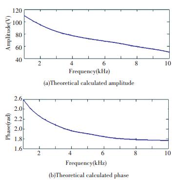
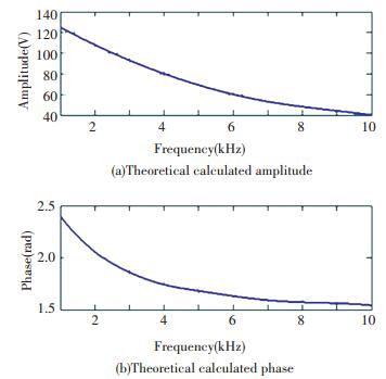
The front and back piezoelectric ceramic are the same, ρ= 2 430 kg·m-3, ε33S=174.3ε0, e33= 3.95 C·m-2, and the acoustic impedance ρCtD= 7.6×10⁶ kg(m2·s)-1. The diameter of the piezoelectric ceramic d= 100 mm and t= 1.5 mm. If the amplitude of the incidence wave is 1.00 Pa, according to Eqs.(12)-(15), the theoretical calculated amplitude and phase of the front and back piezoelectric ceramics are shown in Figs. 6-7.
|
Figure 6 The theoretical calculated amplitude and phase of the front piezoelectric |
|
Figure 7 The theoretical calculated amplitude and phase of the back piezoelectric ceramic |
4 Controlling Theory
If the voltage V1 and V2 measured by the PVDF 1 and PVDF 2 are used by z transforms, the error signal can be defined as:
| $ {E_1}\left( z \right) = {H_{12}}\left( z \right){V_1}\left( z \right) - {V_2}\left( z \right) $ |
where V1(z) and V2(z) are the z transforms of the voltage signals from the PVDF 1 and PVDF 2, H12(z) is the desired transfer function between them. For sound consisting only of plane waves, the transfer function is
| $ {H_{12}}\left( {{\rm{j}}\omega } \right) = \frac{{\frac{{{Z_d}\left( {{\rm{j}}\omega } \right)}}{{\rho c}} - {\rm{jtan}}\left( {\frac{{\omega \tau }}{2}} \right)}}{{\frac{{{Z_d}\left( {{\rm{j}}\omega } \right)}}{{\rho c}} + {\rm{jtan}}\left( {\frac{{\omega \tau }}{2}} \right)}} $ | (16) |
where Zd(jω) is the desired acoustic impedance. In the particular case when the desired acoustic impedance is Zd(jω)=ρc, corresponding to a perfectly absorption, the Eq.(16) simplifies to a time delay:
| $ {H_{12}}\left( {{\rm{j}}\omega } \right) = \exp \left( { - {\rm{j}}\omega \tau } \right) $ |
This can be readily transformed to a digital transfer function if the sampling period is chosen as an integer fraction N of the acoustic time delay, Ts=τ/N, in this case the digital transfer function reduces simply to a delay of N samples:
| $ {H_{12}}\left( z \right) = \exp \left( { - N} \right) $ |
In the time domain, the error signal is then calculated as:
| $ \begin{array}{*{20}{c}} {{e_1}\left( k \right) = {V_1}\left( {k - N} \right) - {V_2}\left( k \right)}\\ {{e_2}\left( k \right) = {V_3} = \left( k \right) = 0} \end{array} $ |
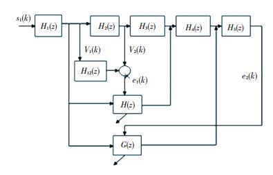
The control system is shown in Fig. 8. In Fig. 8, H1(z) is the transfer function between the sound source and the PVDF 1, H2(z) is the transfer function between the PVDF 1 and the PVDF 2, H3(z) is the transfer function between the PVDF 2 and the front piezoelectric ceramic, H4(z) is the transfer function between the front piezoelectric ceramic and the back piezoelectric ceramic, H5(z) is the transfer function between the back piezoelectric ceramic and the PVDF 3.
|
Figure 8 The control system |
5 Experiment
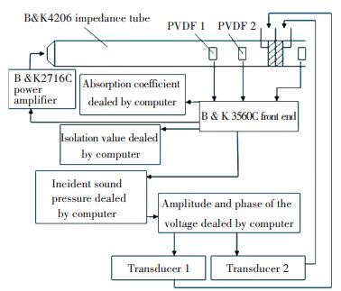
A Kundt impedance tube 4002 is used for this experiment whose diameter is 10 cm and length is 3 m. The experimental arrangement figure is shown in Fig. 9.
|
Figure 9 The experimental arrangement |
The primary source is a loudspeaker, the distance between the two pieces of PVDF is 2.5 cm and the distance between the PVDF 2 and the piezoelectric ceramic 1 is 2.5 cm. The distance between the PVDF 3 and the piezoelectric ceramic 2 is 2.5 cm. ρ= 1.21 kg/m3, the propagation velocity in the air is c= 343 m/s, and t= 1.5 mm, ρ= 2 430 kg/m3, ρCtD= 7.6×10⁶ kg/(m2·s), ε33S= 174.3 ε0, e33= 3.95 C/m2. The specification of the three pieces of PVDF is same which is 10 mm×10 mm×0.5 mm(Length×width×thickness). The density, the propagation velocity in the PVDF, the dielectric constant of the PVDF are ρ= 7 500 kg/m3, ct= 5 750 m/s, ε33S=1 200ε0.
If the loudspeaker emitted the plane wave, the signals of the two PVDF passed by the circuit module designed for measuring the incidence and the reflection sound pressure and disposed with the computer, so that the reflection pressure is obtained, at the same time, the voltage is applied on the piezoelectric ceramic passing the filter controller. The function of the two microphones is not only to measure the incidence and reflection wave, but also to adaptively control as error transducers. The experimental frequency is from 1 000 Hz to 5 000 Hz. Although the second mode of the 100 mm diameter tube is closed to 2 000 Hz, another experiment arranged as Fig. 9 is carried out in an anechoic chamber, the last measured absorption coefficient is little contrast to the absorption coefficient measured in the tube mentioned in Fig. 9. Thus the last result measured in the tube is used in this paper.
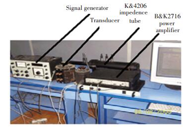
The practicality figure of the experimental arrangement is shown in Fig. 10.
|
Figure 10 The practicality figure of the experimental arrangement |
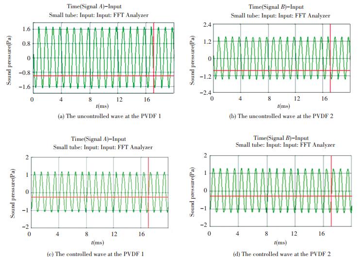
The frequency and the amplitude of the incidence wave are 1 000 Hz and 1.00 Pa respectively. The uncontrolled and controlled wave at the PVDF 1 and PVDF 2 are shown in Fig. 11. In all figures, the symbol m represents milli and s represents second.
|
Figure 11 The uncontrolled and controlled waves at the microphone 1 and microphone 2 with the incident frequency 1 kHz |
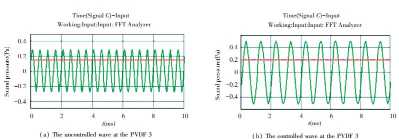
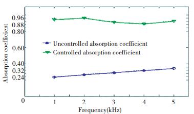
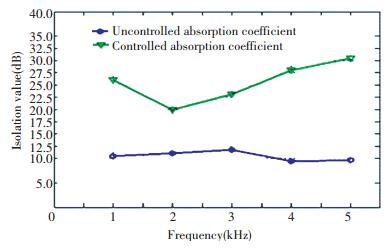
The uncontrolled and controlled waves at the PVDF 3 are shown in Fig. 12. The absorption coefficient before controlled and after controlled is shown in Fig. 13. The isolation value before controlled and after controlled is shown in Fig. 14.
|
Figure 12 The uncontrolled and controlled waves at the PVDF 3 with the incident frequency 1 kHz |
|
Figure 13 The absorption coefficient before controlled and after controlled |
|
Figure 14 The isolation value before controlled and after controlled |
According to the Fig. 13, the absorption coefficient before controlled is lower than 0.4, after controlled, the absorption coefficient reaches to 0.9 at all measured frequency.
According to the Fig. 14, the isolation value before controlled is lower than 12.5 dB, after controlled, the isolation value reaches to 30 dB at 5 000 Hz.
So the experiment results denote that the active absorption and active isolation theory is correct and feasible.
6 ConclusionsIn this paper, two pieces of piezoelectric ceramic are used as materials of active absorption and active isolation, two pieces of PVDF with equal distance are placed in the front of the material in order to measure the incidence plane wave and the reflected wave, the voltages are applied on the surface of material in order to make the reflected wave and transmission wave be zero using the adaptive controlling. The way to view this method mentioned in this paper is that the acoustic impedance of the active surface is displaced to match the dynamic incident acoustic pressure wave. This means that the incident pressure travels into the boundary as if it is an infinite medium. This concept is different from many traditional and commercial active acoustic systems approaches in that it matches the impedance of an acoustic boundary surface such that an incident disturbance will not reflect and transmit from the boundary. The experiment results denote that the active absorption and active isolation theory is correct and feasible.
| [1] |
Eriksson L J. Recent trends in the development of active sound and vibration control systems.
Proc. Noise-Con's, 1994: 271-278.
( 0) 0)
|
| [2] |
Paul L. Process of Silencing Sound Oscillations. U. S. Patent No. 2043416, 1936.
( 0) 0)
|
| [3] |
GuicRing D, Karcher K, Roll Wage M. Active control of the acoustic reflection coefficient at low frequencies.
Proceedings of Inter-Noise'83, 1983: 419-422.
( 0) 0)
|
| [4] |
Fuller C R. Optimal placement of piezoelectric actuators and polyviny license fluoride error sensors in active structural acoustic control approach.
J. Acoust. Soc. Am, 1992, 92(3): 1521-1533.
DOI:10.1121/1.403944 ( 0) 0)
|
| [5] |
Robert L, Fuller C R. Modal cell sing of ehicrent acoustic radiators with polyviuylidenle fluoride distributed sensors in active structural acoustic control approach.
J. Acoust. Soc. Am, 1992, 91(6): 3321-3329.
DOI:10.1121/1.402822 ( 0) 0)
|
| [6] |
Fuller C R. Active structural acoustic control.
J. Acoust. Soc. Am, 1992, 91(1): 519-520.
DOI:10.1121/1.402743 ( 0) 0)
|
| [7] |
Wang Bor-Tsuen. The pouf-based wave number domain sensing techniques for active sound radiation control from a simply supported beam.
J. Acoust. Soc. Am, 1998, 103(4): 1904-1915.
DOI:10.1121/1.421342 ( 0) 0)
|
| [8] |
Eghtesadi K, Leventhall H G. Active attenuation of noise-The monopole system.
Journal of the Acoustical Society of America, 1982, 71: 608-611.
DOI:10.1121/1.387532 ( 0) 0)
|
| [9] |
Swinbanks M A. The active control of sound propagation in long ducts.
Journal of Sound and Vibration, 1973, 27(3): 411-436.
DOI:10.1016/S0022-460X(73)80355-4 ( 0) 0)
|
| [10] |
Trinder M C J, Nelson P A. Active noise control in finite length ducts.
Journal of Sound and Vibration, 1983, 89(1): 95-105.
DOI:10.1016/0022-460X(83)90913-6 ( 0) 0)
|
| [11] |
Mangiante G. Active noise control in a duct: The JMC method. Proceedings of the International Conference on Noise Control Engineering.
Poughkeepsie, NY: Noise Control Foundation Inc., 1990: 1297-1300.
( 0) 0)
|
| [12] |
Berlincourt D.
Ultrasonic Crystals and Ceramics. New York: Piezoelectric Crystals and Ceramics, 1971.
( 0) 0)
|
| [13] |
Congnyun Z. Computation of the driving voltage applied across the lay in single and double layers of piezoelectric material for active sound absorption.
Journal of Vibroengineering, 2014, 25(1): 2503-2536.
( 0) 0)
|
| [14] |
Moon Won-kyu, Busch-Vishniac Llene J. A finite-element equivalent bond graph modeling approach with application to the piezoelectric thickness vibrator.
Journal of the Acoustical Society of America, 1993, 6: 3496-3506.
( 0) 0)
|
| [15] |
Harris Gerald R, Gammell Paul M. Sensitivity measurements of piezoelectric polymer hydrophones from 0.2-2 MHz using a broadband-pulse technique.
Journal of the Acoustical Society of America, 1999, 105(2): 725-729.
DOI:10.1121/1.426263 ( 0) 0)
|
| [16] |
Moon Won-kyu, Busch-Vishniac Llene J. A finite-element equivalent bond graph modeling approach with application to the piezoelectric thickness vibrator.
Journal of the Acoustical Society of America, 1993, 93(6): 3496-3506.
DOI:10.1121/1.405680 ( 0) 0)
|
| [17] |
Hazony D. Piezoelectric transducers with ideal time limited impulse response.
Journal of the Acoustical Society of America, 1981, 70(3): 661-662.
DOI:10.1121/1.386927 ( 0) 0)
|
| [18] |
Stefano Marselli, Vittorio Pavia. Porous piezoelectric ceramic hydrophone.
Journal of the Acoustical Society of America, 1999, 106(2): 456-475.
DOI:10.1121/1.427091 ( 0) 0)
|
| [19] |
Hikita K, Yamada K, Nishioka M, et al. Piezoelectric properties of the porous PZT and porous PZT composite with silicone rubber.
Ferroelectrics, 1983, 49: 265-270.
DOI:10.1080/00150198308244698 ( 0) 0)
|
| [20] |
Ting R Y. Piezoelectric properties of a porous PZT ceramic.
Ferroelectrics, 1985, 65: 11-16.
DOI:10.1080/00150198508008955 ( 0) 0)
|
| [21] |
Sornette D, Lagier M, Roux S, et al. Critical piezoelectricity in percolation.
Journal of Physics, 1989, 50: 2201-2210.
DOI:10.1121/1.2025645 ( 0) 0)
|
 2017, Vol. 24


