 2017, Vol. 24


2. Department of Aerospace Engineering, Harbin Institute of Technology, Harbin 150001, China
The software development method based on MDA (model-driven architecture) has aroused great concern in the academic community in recent years[1-2].OMG first proposed MDA. It is a methodology and standard system, through the model transformation to drive the system development, the software system is built on the basis of a variety of models.Now the model-driven software development is a hot topic in the field of software engineering, and has become a new software development paradigm to improve the quality and efficiency of software.Where code generation technology is an important part of MDA, it means that the generator reads the script or document associated with the graphics model and generates high-level language programs like C, C ++, Java, Perl, Ruby, Python, and HTML etc.
There are many of the related research on automatic code generation, such as the metadata-driven automatic code generation solution based on the Net architecture[3].The tools-based design pattern can automatically generate abstract-level design patterns[4]; UML-based model of automatic code generation technology can generate system architecture, while the generated code can reflect the original model of the hierarchy[5].Tools such as B4S and Rhapsody, based on state machines, can generate code that can run on its real-time framework.
The flowchart plays an important role in the system requirements analysis, the preliminary design and the detailed design stage. It is particularly important in the discussion, analysis and design of algorithms[6-9].However, the traditional use of the flowchart is limited to description, communication and display, and its role is limited to intuitive, clear, simple communication and document compilation.Thus, generating code from the flowchart will be very important, and it will allow designers to design systems from advanced functions without the concerning for complex structural code, which is more in line with MDA's goals[10-11].
Hemlata Dakhore proposed an XML parser-based strategy to generate code[12]. But this article does not discuss how to identify the semantics of specific flowcharts. That is, there is no discussion of the "selection", "loop" and "nested" structures. From the method, it must first be determined whether the Judgment constructs a selection or a loop, which must be specified by the modeler in advance. If so, it will lose the convenience and flexibility of the flowchart model, as well as lack of intelligence and automation.This paper only gives a simple example, how can flowchart be converted to XML and automatically generate code is not discussed.
Now many countries have developed various MDD development tools, some of them which have the ability of generating codes from graphic models are shown in Table 1. It can be seen that these tools are all used to describe the framework of the software system. Among all of them only IBM Rhapsody supports algorithm logic modeling and code generation, but it only supports unstructured flow chart (without error check and with lots of 'goto').
| Table 1 The ability of code generation for some mainstream MDD tools |
2 Related Research and Main Contribution 2.1 Automatic Code Generation Based on State Diagram
UML state diagram has rich semantics to model response systems based on state machine, and the semantics of 'state', 'event', 'action' are its basic elements. When external event occurs, the program will turn into target state after executing specific actions. IBM Rhapsody is a mature and representative MDD tool that supports automatic code generation from state diagram. It contains a real-time framework called OXF where the generated state machine functions can be executed. The generated code contains two parts, one is state machine function framework itself, and the other one is OXF[13-14]. Another real-time framework is an open source project called Quantum Platform. It is also a development method based on state machine (see its handbook in Ref.[15]). See Fig. 1 for its detailed hierarchy.

|
Figure 1 Quantum Platform |
Similarly, some scholars carried out the research of automatic code generation based on Quantum Platform, and also achieved good results[16-17].
It can be seen from above achievements that only the system function framework of a specific application can be constructed, while the detailed processing logic for each action muse be written manually.
2.2 Automatic Code Generation Based on Flowchart(1) Unstructured and structured program design
Unstructured programming is the most original programming mode. This mode has been criticized because of some shortcomings, in which the most serious is that it will produce lots of codes which are hardly to be understood (dubbed as "spaghetti"). After that, there have been structured (procedural) programming and object-oriented programming[18-19].
Structured programming is a basic detailed design method and is carried out by taking modules and processes as input. Structured flowchart is a basic assist means for structured program design. The GOTO statement in structured programming is prohibited, but in certain circumstances, such as that the program readability is improved rather than undermined, it can be used.
Shortcomings:GOTO statement undermines the consistency between the static structure and dynamic execution of the program; GOTO statement makes the program be difficult to be red and checked; GOTO statement will produce bad impact on program testing, and also the program correctness is difficult to be proved, GOTO statement will affect the program optimization.
Advantages:Non-normal exit of the block or process often requires GOTO statement; GOTO statement tends to make program execute efficiently, and is convenient and flexible; GOTO statement can easily be used to make the program jump out of the loop structure (even nested loops); with the continuous development of computer hardware technology, the structure of the program becomes even more important, so that structured design has become a mainstream method.
(2) Automatic code generation for flowchart
Unstructured flowchart:In 2007, IBM company acquired 'Telelogic' product, and then launched a new software product called 'Rational Telelogic Rhapsody' based on it, by the end of December 2013 its latest version is updated to V8.0.5. Now Rhapsody has become a leading embedded and real-time software development MDD tool. It can generate framework code according to the state diagram semantic[13-14]. It supports unstructured flowchart modeling in the latest version, but it can not recognize unstructured errors, so the generated codes include lots of 'goto' statements. As the use of unstructured flowchart in Rhapsody, some deficiencies will exist naturally. All the unstructured errors unable to be recognized are substituted by 'GOTO' statement universally. Obviously, it plays a negative role in the aspects of the reliability, security and correctness of program design.
Structured flowchart: SFC[20]is an algorithm description tool based on structured flowchart designed by Martin C in Sonoma State University. It can be used to generate code from flowchart. But its operation is mechanical, the designer can only insert pre-standard graphical elements from fixed points, the flexibility is very low and its operation is not convenient and lack of scalability. As the flowchart structure type has been specified by the designer during the modeling stage, there is no need to recognize the structure itself, and also the code can be generated accompanied in modeling process. This method causes a fatal flaw in the case of design changes, because the connection structure can not be easily changed, in other words, it is not capable of drag connection. It leads to a certain deviation from the original intention of flowchart, i.e., independent of the programming language.
2.3 Main ContributionFlowchart can provide intuitive description for detailed processing logic, and they are fully complementary in the level of code generation. This paper presents a structure recognition algorithm and unstructured error recognition algorithm for structured flowchart, and also puts forward a corresponding automatic code generation algorithm. The algorithm time complexity is analyzed and the effectiveness of the error recognition algorithm is tested. The error recognition algorithm can recognize the errors in the fault flowcharts that we can construct now. The comparative experiments between the proposed algorithms and Rhapsody show that the proposed algorithms have obvious advantages.
The main problem of code generation from flowchart is how to recognize the complex structure, including the basic recognition criterion for basic and complex nested structures of 'do-while', 'selection' and 'while', and how to recognize and locate unstructured errors during the recognition process.
3 Structured FlowchartAny complex algorithm can be composed of three basic structures, namely, sequence, selection and loop. These basic structures can be coordinated, they can contain each other, but can not cross from the structure and jump directly to another structure.Because the whole algorithm consists of three basic structures, so it has a clear structure, and is easy to verify and correct the wrong features[21-22].
The flowchart is independent of any programming language. As shown in Fig. 2. Any complex flowchart can be constructed by combining or nesting of five basic structures. There are a number of tools that support flowchart modeling, such as Rose, Visio, Rhapdosy and so on.

|
Figure 2 Five structures of structured flowchart |
In order to make the flowchart model clearer, more intuitive, as shown in Fig. 2, in addition to the sequence structure, the remaining four structures contain a judgment node, when exiting of the current structure, the convergence node must be used, as shown in Fig. 3.

|
Figure 3 Examples of convergence |
In this paper we use the common five kinds of primitives for flowchart to generate code automatically, and they are: "Begin", "End", "Process", "Judgment" and "Convergence".
For each structure there is an entry node called SEN, see Fig. 4. The three basic structures with Convergence as exit node are shown in Fig. 5.

|
Figure 4 SEN schematic diagram |

|
Figure 5 Three basic structures |
4 Structure Recognition 4.1 Recognition Method
First the three structures all contain Convergence, and one Judgment matches one Convergence. So the following criteria can be obtained.
(1) For loop structure the in-degree sum of Convergence must be one and Convergence must connect the Judgment directly. For Selection structure the in-degree sum of Convergence must be more than one.
(2) Define NodeTimeStamp for every node with initial value 0. Based on depth-first strategy, use a stack to store the Judgment that has not been recognized. For while/for and do-while we can compare the NodeTimeStamp of another son of Judgment with the NodeTimeStamp of Convergence.
4.2 Algorithm Description| Algorithm: ETSP1_Identify |
| Function: Based on depth-first strategy to recognize all Judgments, and use NodeTimeStamp to recognize while/for and do-while. Input:flowchart Output:flowchart and structured information |
| Node BeginNode←Begin; //Initial value ETSP1_Identify (BeginNode) //start recursion Int TimeStamp=0 ETSP1_Identify(Node CurrentNod) { If(CurrentNode has been traversed) or (CurrentNode is End) return If NodeTimeStamp < > 0 then [1] CurrentNode.NodeTimeStamp=++TimeStamp //global unique If (CurrentNode is Judgement) and (CurrentNode has not been identified) [2] and (CurrentNode is not in Stack) then Stack.push(CurrentNode) If (CurrentNode is Convergence) then [3] match (CurrentNode, Stack.top) // match Convergence and Judgement return For each son of CurrentNode [4] ETSP1_Identify (son) If (CurrentNode is Judgement) then [5]break/> If CurrentNode.Convergence.Indegree>1 then CurrentNode.Attr←selection[1] Else [5-2] Get another son of CurrentNode who is not convergence as Tson If Tson.NodeTimeStamp < CurrentNode.NodeTimeStamp then CurrentNode.Attr←do-while[5-3] store CurrentNode into Tson.nestList Else CurrentNode.Attr←while/for Stack.pop [5-3] ETSP1_Identify (CurrentNode. Convergence.son)[5-4] // can only have one son } |
SF1) The sum of Convergence and Judgment must be the same.
SF2) The Judgment of Loop structure must connect to Convergence node directly.
SF3) The out-degree of Judgment for loop structure must be equal to 2.
SF4) The out-degree of Judgment and in-degree of Convergence for selection structure must be equal.
SF5) Judgment node can not directly connect two Convergence nodes.
SF6) A Convergence node can only be associated with one Judgment node.
SF7) The out-degree of Convergence node can only be one.
SF8) The out-degree of Judgment for Loop structure must be equal to 1, and greater than 1 for selection structure.
SF9) Start node has no in-degree and can only have one out-degree, End node has no out-degree and can have multiple in-degree (>1).
SF10) Process node can only have one out-degree.
SF11) Any Judgment node can only be recognized as one type of structure.
SF12) Each Judgment node must be recognized when recognition process is completed (run to End).
SF13) When recognition process is completed, Stack must be empty (has no Judgment).
5.2 Error Recognition Algorithm(1) The basic idea of the algorithm
Input constraints:
1) Flowchart has been recognized by the above proposed algorithm;
2) SEN of do-while has been built relationship with its Judgment and Convergence nodes;
3) The relationship between Judgment and Convergence for while/for and selection structure has been constructed.
Definition 1 Structure appearance order (JCounter)During the traversal process, when control flow arrives at a new structure, do JCounter++, i.e., if a Judgment of 'selection'\\'while/for' or SEN of do-while is reached for the first time, then do JCounter++.
Definition 2 Judgment Stack JudgeStack < CJN_SEN, Counter, CVG>: where CJN_SEN is SEN, Counter is the appearance order (JCounter) of current CJN_SEN, CVG is the Convergence of current structure where CJN_SEN is located.
Definition 3 Node Team Counting (TeamCounter), Let L(x) be father of L(y), i.e., L(s) contains L(y), and L(y) contains no other structures. Then assign a team counter variable (YTC) for each node in L(y): (a) the values of TeamCounter are the same; (b) and the value of XTC is different for the nodes in (L(x)-L(y)).
Definition 4 Node marked counter, the sum of setting TeamCounter.
Core processes: Traverse from Begin node by depth-first strategy, if current node is SEN of do-while structure, then according to the nested layer, from the outmost layer to generate JudgeStack elements and push them into stack. Then process Judgment of while/for and selection structures by the same way.
Assign NodeMarkedCounter for current node, further process the son of current node, and judge whether return or recursion, if its son is CVG of the top element of JudgeStack, then return. If all the sons of current node have been processed, then judge whether current node is CJN_SEN of the top element of JudgeStack or not, if yes, it demonstrates that the top of stack has been processed completed, then process subsequent nodes by the CVG of top of JudgeStack.
Error Recognition: Error recognition algorithm can recognize seven different feature type of error at the different point in the algorithm, for the detail see Table 2 and ESFC_FaultRecognize algorithm.
| Table 2 ESFC error recognition type and core process |
(2) Algorithm description
| Name:ESFC_FaultRecognize Input: Recognized flowchart. Process: Depth-first traverse, unstructured error check. Output: Error and information. |
| Define JCounter=1 /* global counter for Judgment nodes */ Define node.TeamCounter=0 /*TeamCounter*/ Define NodeMarkedCounter=0 // Node marked counter Define NodeSum //node sum contained in flowchart Define ConvergenceSum // Convergence sum contained in flowchart ESFC_FaultRecognize (Begin) // start recursion If(NodeMarkedCounter+ ConvergenceSum < NodeSum) then print error information, stop [F1] // node has not been processed. ESFC_FaultRecognize (Node currentNode) { If(currentNode is SEN of do-while) then [1] For n nests from the outermost level do [1-1] JCounter ++, MarkCounter= JCounter JudgeStack.push(currentNode, MarkCounter, currentStructure.Convergence) If(currentNode is Judgement of while/for or selection) then [2] JCounter ++, MarkCounter= JCounter JudgeStack.push(currentNode, MarkCounter, currentNode.Convergence) If node.TeamCounter==0 then [3]// all the node should be numbered except Convergence node If (currentNode is Judgement) and ( MarkCounter has been used by other Judgement) then print error information, stop [F2]// the number for Judgment node must be unique node.TeamCounter= MarkCounter NodeMarkedCounter++// increment else if and node.TeamCounter<> MarkCounter [4] print error information, stop [F3] If (currentNode is End) then [5] If JudgeStack is not empty then print error information, stop [F7] return If (currentNode is not Judgement of do-while) then [6] for each son of currentNode do [6-1] // Control flow directly goes into the outer structure from inner structure, and do not exit from Convergence node. If (son is a Convergence) then ConvergenceSum++ // Convergence node counter If son has been Traversed and currentNode.TeamCounter < son.TeamCounter then print error information, stop [F4] If son is JudgeStack.top.CJN_SEN or is JudgeStack.top.CVG or has been Traversed then continue Else If (son is a Convergence and is not JudgeStack.top.CVG) then print error information, stop [F5] else ESFC_FaultRecognize(son) If (currentNode is JudgeStack.top.CJN_SEN) then [7] Temp_top=JudgeStack.pop MarkCounter=JudgeStack.top.Counter If (Temp_top.CVG.son has been traversed) then print error information, stop [F6] If (Temp_top.CVG.son is Convergence) then return // return to father structure ESFC_FaultRecognize(Temp_top.CVG.son) // process successor node of Convergence node. } |
5.3 Examples of Error Recognition
Most of the errors can be recognized based on criteria SF1-SF12, for deep structural errors we can use ESFC_FaultRecognize algorithm to recognize. Through the experiment, all the error structures we can build are effectively recognized, and some examples are shown as shown in Table 3.
| Table 3 Error examples and recognition basis |

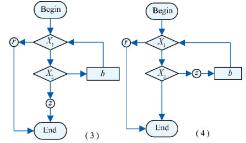

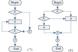
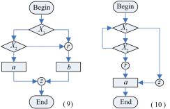
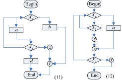
We used ESCB_Recognize to recognize structural features, then used ESFC_FaultRecognize and criteria SF1-SF12 to check errors based on recognized structural results.
6 Code Generation 6.1 Algorithm DescriptionAlso automatic code generation from the recognized flowchart is a recursion process based on depth-first strategy.
First define a StringBuffer variable to cache the generated C code, and then start from Begin node to traverse, if the program arrives at the End or Convergence nodes, then return.
If the execution arrives at a Process node and the node is not SEN of do-while structure then write the code of the Process node into the cache variable, and then begin to recursively process following nodes.
If the execution arrives at SEN of a do-while structure, then use this node to generate do-while code block. Generation process follows the order from the inside to the outside, i.e., first the innermost layer is generated, and then the outer layer.
Generation process for 'While\\For' or 'If\\Switch' structures located in the innermost layer is similar to the above case. The difference is that there is only one branch in while/for structure but multi-branches in selection structure. The algorithm is described as follows:
| Function: code generation Input: the recognized flowchart Output: program code |
| Node start; // The began node StringBuffer buffer; // Used to cache the generated code CodeGenerate(start, buffer); // Start recursion from begin node CodeGenerate(Node node, StringBuffer buff) { if (node is a kind of EndNode) { // Return if arrive at end node. return; } else if (node is a MergePoint) { // Return if arrive at Convergence node. return; }else if(node is a kind of ProcessNode) { // Arrive at Process node if(node. depthCounter ==0) { // Not in a do-while block, or in the innermost do-while block buff.append(node.code); // Store the code of Process node into cache variable CodeGenerate(node.next, buff); // Continue recursion } else { // Lays in a do-while block decision←getRelatedDecision(node); // Obtain the corresponding Convergence node node.depthCounter--; // Nesting level -1 CodeGenerate(decision, buff); //Generate a do-while code block } }else if(node is a kind of DecisionNode) { //Arrives at a Judgment node if(node.visited is True) // Judgment node has been traversed, return return; Node.visited←True; // Mark the traversed node if(node.type is do-while and node is not visited) { //do-while structure Node.visited←True; // Mark the traversed node StringBuffer codeOfDo; Code Generate(node.firstNode, codeOfDo); //Generate do code block //Generate a complete "do {...} while (...); " code blocks StringBuffer doWhileCode←"do{"+codeOfDo+"}while("+node.loopCondition+"); "; buff.append(doWhileCode); //cache CodeGenerate(node.mergePoint.next, buff); } // Recursively process the next node of the Convergence node. else if(currentNode. depthCounter!=0){ // In a do-while block. decision←getRelatedDecision(node); // Obtain the corresponding Judgment node. node.depth Counter--; // Nesting level -1 CodeGenerate(decision, buff); } // Generate do-while code block else if(node.type is while\for) { //While\for structure StringBuffer codeOfDo; Node next←getLoopNode(node); // Get the next node of the Convergence. CodeGenerate(next, codeOfDo); // Generate do-while code block // Generate a complete "while\for(…) {…}; " code blocks StringBuffer loopCode←"while\for("+node.loopCondition+"){"+codeOfDo+"}"; buff.append(loopCode); //cache CodeGenerate(node.mergePoint.next, buff); // Recursively process the next node of the Convergence node. } else if(node.type is if\switch) { //if\switch structure For each (next of node) do { // Process each branch StringBuffer branchCode; Code Generate (node.next, branchCode); // Generatebranch code block // Generate a complete "if(…) {…}; or case …:{… break; };" code blocks branchCode←"if("+branch Condition+"){"+ branchCode +"}"; or branchCode←" case "+branchCondition+":{"+ branchCode +" break; }"; buff.append(branchCode); //cacahe } CodeGenerate (node.mergePoint.next, buff); // Recursively process the next node of the Convergence node. } } } |
6.2 Time Complexity Analysis
If there is no do-while structure, the recursion is executed only once when current node is processed, and the execution number in each recursion is a constant, so the algorithm complexity is O(n).
If there are do-while structures, the SEN of do-while will be traversed twice. So if there are n nodes in a flowchart(as shown in Fig. 6), the whole structure is only constructed by nested do-while.

|
Figure 6 'do-while' deep self-nesting |
In this case, the number of Judgment node is (n-3)/2, after finishing to process Judgment node the control flow will re-enter node A, when all the Judgment nodes have been processed, node A will be re-entered again, so node A will be processed (n-3)/2+1 times, all the other nodes will be processed only once. So the total recursion sum is (n-3)/2+1+(n-1)=1.5(n-1). Obviously, n must be a odd (every Judgment node has a Convergence).
So the time complexity is also O(n) in the worst-case.
7 Application SystemWe have developed a tool based on the Eclipse platform and the Graphics Editor Framework (GEF), the functions include flowchart modeling and code generation. At the same time, compilation tools (GCC), code editor (CDT) and debugging tools (GDB) are integrated into this tool.
Constructing systems using flowcharts: Tasks and interrupt services can be modeled, the tool can generate instances of tasks or interrupts, and also support nested flowchart models and code generation.
Variable and header file management: including global variables, local variables, macros and various header files.
The overall system interface is shown in Fig. 7.

|
Figure 7 Overall interface of integrated development platform |
We build a model to test a variety of complex nested structures. As shown in Fig. 7, there are five structures: switch, for, while, do-while and if-else. In the first branch, we create two sub-flowcharts, the type of automatic code generation is the source code block (all generated code will be placed in the original position) and the function call (all generated code will be placed in function, in the original place there will be a function call statement).
Since the program code in TempCode is not formatted, the third part tool should be called to format the file when writing the file to the text file, where we use Codeblocks.
In Fig. 8, the left one is a source-block type (while nests while), the right one is function-call type (do-while nested do-while).

|
Figure 8 Nested sub-flowcharts |
The generated code is shown below.
| /*Task_1.c*/ #include "Task_2.h" #include "sub_flowchart_fun_call.h" void Task_2() { unsigned int inner_var; unsigned int inner_var2 = 44; int i=10; switch(inner_var) { case 3 : { for (inner_var = 0; inner_var < 10; inner_var ++) { printf("this is a for condition"); } break; } case 2 : { while (inner_var < 0) { printf("this is a while condition"); } break; } case 1 : { do { printf("this is a do_while condition"); } while (inner_var < 0); break; } case 0 : { if (inner_var2 > 0) { while (1) /* Generated by sub-flowchart, the type is source-block */ { while (i--) { printf("this is a sub-flowchart"); } } } else { sub_flowchart_fun_call(); /*Generated by sub-flowchart, the type is function-call */ } break; } } } |
|
/*sub_flowchart_fun_call.h*/
#ifndef sub_flowchart_fun_call_h #define sub_flowchart_fun_call_h #include "GLOBALHEAD.h" void sub_flowchart_fun_call (); #endif |
|
/*sub_flowchart_fun_call.c*/
#include "sub_flowchart_fun_call.h" void sub_flowchart_fun_call () { int i=10; do { do { printf("this is sub_flowchart function call"); } while (i--); } while (1); } |
8 Comparative Test with Existing Tools 8.1 Unstructured Flowchart Modeling and Automatic Code Generation with 'goto'
Rhapsody has the ability of generating code based on unstructured flowchart. The structure recognition process strictly depends on the condition (guard condition) in the flow line, as a result, when an error condition occurs in the flow line, the structure will not be recognized correctly, and lots of 'goto' statements will be generated. The structure recognition algorithm proposed in this paper is more reasonable and reliable, because it only depends on the relationship between the nodes represented by flow-lines, by this way the condition in the flow-line affects only logical expression in the generated code. While algorithm based on structural features can further check the correctness of guard conditions.
We cannot know the specific algorithm used by Rhapsody according to the literatures we can get and the software manuals. But we can check the correctness and validity of the algorithm used by Rhapsody depending on the results of software execution. Here we just give a part of test for guard conditions in a specific flowchart based on Rhapsody. An example flowchart is shown in Fig. 9.

|
Figure 9 Flowchart and guard condition in Rhapsody |
It can be seen from Table 4 that only the example in the first row can be recognized correctly and correct codes are generated, for the rest examples lots of 'goto' statements are generated.
| Table 4 Test for guard condition and code generation |
8.2 Structured Flowchart Modeling and Flexibility
SFC EDITOR is a structured flowchart modeling tool, and it can be used to describe algorithm and generate C code. For its usage, a new insertion for a specific structure must be at an insert-point in current graphic, and after insertion, some new legitimate insert points will be produced in the connected lines. We can see the designer can only select specific structure and insert them into the specific insert-point mechanically. As the designer must insert new specific structure according to the SFC rules, so the current flowchart will be always specific, furthermore, there is no need to recognize structure in the code generation process. But when the designers want to change the flowchart structure, they can not do it by changing the connection line in drag way, they can only delete current structures and again add new structures by single-step way, so we can see the previous work will be lost. Obviously, the operation is very mechanical and not flexible. See Fig. 10.

|
Figure 10 Screenshot of SFC EDITOR |
SICAS is a learning tool designed to help students in developing their basic algorithmic and enhancing programming skills. It can be used to design, simulate, test and compare algorithms for different problems. As shown in Fig. 11, the notation hexagonal represents LOOPING, diamond represents SELECTION. SICAS does not support flowline either. All the newly added elements must be inserted at a specific insertion point.

|
Figure 11 Screenshot of SICAS |
ProGuide is a dialogue based tool which can be used to stimulate and guide through a text-based dialogue to support program development. As shown in Fig. 12, insertion points and predefined structures (Hexagon represents LOOPING, diamonds represents SELECTION) are used, but flowline-drag modeling is not supported.

|
Figure 12 Screenshot of ProGuide |
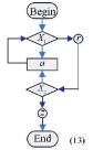
RAPTOR:RAPTOR is a visual programming environment specifically designed to help envision algorithms and to avoid syntactic baggage. RAPTOR programs can be visually created and executed by tracing the execution through the program to minimize the syntax required. Algorithms can be preferably created visually using RAPTOR as shown in Fig. 13. Depending on the predefined features of SELECTION and LOOPING, specific atomic elements or predefined structures can be inserted at the insertion point, and flowline-drag modeling is not supported for lack of flowline model element.

|
Figure 13 Screenshot of RAPTOR |
9 Conclusions
The previous CG-SFCs have little ability of error recognition. This paper not only presents structure feature recognition and code generation algorithms for structured flowchart, but also proposes an algorithm and some criterion to check whether a given flowchart is structural, and it can also be used to check the semantic and structure errors, which greatly enhances the usefulness of the code generation algorithm. Through the comparing with current CG-SFC tools, the proposed algorithms and method have obvious advantages in misidentification, and have better versatility and flexibility.
| [1] |
Zhang Tian, Zhang Yan, Yu Xiaofeng, et al. MDA based design patterns modeling and model transformation.
Journal of Software, 2008, 19(9): 2203-2217.
DOI:10.3724/SP.J.1001.2008.02203 ( 0) 0)
|
| [2] |
Lyu Ruifeng, Wang Gang, Wen Xiaoxian, et al. Process modeling method of calculation independent model level based on MDA.
Computer Integrated Manufacturing Systems, 2008, 14(5): 868-874.
(0)
|
| [3] |
Völter M, Stahl T, Bettin J, et al. Model-driven software development: technology, engineering, management.
John Wiley & Sons, 2013.
(0)
|
| [4] |
Mehmood A, Jawawi D N A. Aspect-oriented model-driven code generation: A systematic mapping study.
Information and Software Technology, 2013, 55(2): 395-411.
DOI:10.1016/j.infsof.2012.09.003 (0)
|
| [5] |
Eshuis R, Wieringal R.
A formal semantics for UML activity diagrams. Enschede: University of Twente, 2001.
(0)
|
| [6] |
Wang Liming, Wang Guonü, Zhou Mingyuan, et al. Research on and implementation of the algorithm from the program flowchart to the code.
Journal of Xidian University, 2012, 6: 70-77.
(0)
|
| [7] |
Wu X H, Qu M C, Liu Z Q, et al. Automatic conversion of structured flowcharts into problem analysis diagram for generation of codes.
Journal of Software, 2012, 7(5): 1109-1120.
(0)
|
| [8] |
Taheri S M, Hidehiko Y, Tripathy H K. Novel assessment of different intelligent tools for problem solving.
Computer Science and Engineering, 2013, 3(3): 67-75.
DOI:10.5923/j.computer.20130303.03 (0)
|
| [9] |
Hooshyar D, Alrashdan Ma.en T, Mikhak M. Flowchart-based programming environments aimed at novices.
International Journal of Innovative Ideas, 2013, 13(1): 52-62.
DOI:10.1504/IJAIP.2015.070343 (0)
|
| [10] |
Sendall S, Kozaczynski W. Model transformation: The heart and soul of model-driven software development.
IEEE Software, 2003, 9: 42-45.
(0)
|
| [11] |
Carlisle M C, Wilson T A, Humphries J W, et al. Raptor: Introducing programming to non-majors with flowcharts.
Journal of Computing Sciences in Colleges, 2004, 19(4): 1-6.
(0)
|
| [12] |
Hemlata Dakhore, Anjali Mahajan. Generation of C-Code Using XML Parser: http://www.rimtengg.com/iscet/proceedings/pdfs/advcomp/149.pdf.
(0)
|
| [13] |
Willert. IBM Rational Rhapsody. http://www.willert.de/ibm-rational-rhapsody/.
(0)
|
| [14] |
Rational Rhapsody Family. Rational Rhapsody family 90-day, no-charge trial. http://www-01.ibm.com/software/awdtools/rhapsody/.
(0)
|
| [15] |
Quantum Leaps. Quantum Platform. http://www.state-machine.com/qp/.
(0)
|
| [16] |
Wagstaff K L, Benowitz E, Byrne D J, et al. Automatic code generation for instrument flight software. http://www.state-machine.com/resources/articles.php.
(0)
|
| [17] |
Samek M. Quantum Programming for Embedded Systems:Toward a Hassle-Free Multithreading.
C/C++ Users Journal, 2002, 3: 1-10.
(0)
|
| [18] |
Wikipedia. Non-structured programming. http://en.wikipedia.org/wiki/Non-structured_programming.
(0)
|
| [19] |
Chen Peijun, Wang Xinjie, Li Xinmei. A general equivalent conversion framework form unstructured flowchart to structured N-S flowchart.
Computer Study, 2010, 12(6): 103-104.
(0)
|
| [20] |
Tia Watts. The SFC editor: a graphical tool for algorithm development.
J. Comput. Small Coll., 2004, 20(2): 73-85.
(0)
|
| [21] |
Nassi I, Shneiderman B. Flowchart techniques for structured programming.
ACM SIGPLAN Notices, 1973, 8(8): 12-26.
DOI:10.1145/953349 (0)
|
| [22] |
Gimpel J F. Contour: a method of preparing structured flowcharts.
ACM SIGPLAN Notices, 1980, 15(10): 35-41.
DOI:10.1145/947727 (0)
|