2. University of Chinese Academy of Science, Beijing 100039, China
In the adaptive optics system, the atmospheric dispersion corrector (ADC) is used to compensate the effect of atmosphere dispersion on the image quality of the telescope system[1-3]. The liner ADC is designed in our adaptive system due to its advantages of compactness and simpleness. By counter-rotation of the two prisms around the optical axis of system, the atmosphere dispersion can be compensated at a real time. The rotation range of the prisms is 90°. According to the optical design, when the relative rotation accuracy of the prisms is less than ±0.2°, the effect of the rotation angle error on the compensation result of the atmosphere dispersion is too small to be ignored. So the rotation angle accuracy of two worms and gears mechanisms used to support the prisms[4]should be better than ±0.1° on the whole rotation process.
There exit a lot of measures to the rotation angle[5]such as mechanical methods, electromagnetic methods and optical methods. Researchers pay more attention to the optical methods[6] due to their non-contact, fine accuracy, high stability and so on. Interference method[7-8], reflection method[9-10]and autocollimation-based method[11-17] are the main optical methods.Among them, autocollimation-based method becomes more and more popular with the development of CCD technology. Yong[15-16] et al. used two or three CCDs to measure the rotation angle, but the measurement precision is limited by the calculation of the spot centroid. Autocollimator can measure the spot centroid precisely, consisting of CCD and collimated beam. As to two dimensional autocollimator, however, it is only good at measuring the azimuth and pitch angle and is hard to measure the rotation angle. Although the reflector is improved[18-19], using the trihedral or square pyramid instead of the plane mirror, the measurement range of rotation angle is less than 1°, which does not satisfy rotation angle measurement demand of the prisms.
Here, on the basis of the autocollimator, a rotation angle measurement system with large range is designed. In Section 2, the theoretical analyses are introduced. The experiment demonstration is described in Section 3. The conclusion and discussion of this study is presented in Section 4 with a short summary.
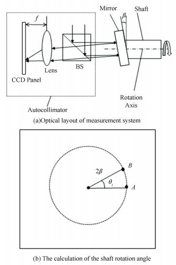
2 Design of the Measurement SystemFig. 1(a) shows a simple rotation angle measurement method based on the autocollimator. The mirror tilting a small angle β to the rotation axis is fixed on the shaft end, which ensures the reflective rays come back to the autocollimator with 2β angle to the optical axis. When the shaft and mirror rotate together, the reflective beam will rotate around the shaft rotation axis and the converged spot will move on the CCD panel with angular radius 2β, θi is the measured rotation angle, as shown in Fig. 1(b). According to the position corresponding relations of the rotating shaft and moving spot, the shaft rotation angle is gotten easily and quickly.
|
Figure 1 Measurement principle of the shaft rotation angle on the basis of the autocollimator |
This measurement system can measure the shaft rotation angle at any rotation position using a brief algorithm and its optical layout is very simple. Only a mirror is needed besides the autocollimator. However, suffered from the installation errors, the clearances of the bearings and the transmission force of the mechanism, the rotation axis is wobbly during the measurement process, leading to the spot deviation and the measurement error will be induced finally.
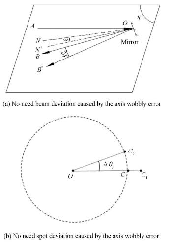
Fig. 2(a) illustrates the effect of the axis wobbly error on the direction of the reflective beam. AO, OB and ON are the incident beam, reflective beam and mirror normal respectively without the influence of axis wobbly error. In the plane η including lines AO and ON, if the axis wobbly error component is δ, it will change the mirror normal from ON to ON′ with angle δ and the reflective beam from OB to OB′ with angle 2δ in the plane η. As shown in Fig. 2(b), this unwanted change of reflective beam will make the spot deviates from C to C1 radially with the angular distance 2δ. All the same, another axis wobbly error component in the plane perpendicular to the plane η also deviates the spot. Paying attention to the radius of the circular trajectory that is about 1 500 arcsec, the measurement error induced by the axis wobbly error whose range is several arcsec to hundred arcsec is too large to be ignored.
|
Figure 2 Analysis of the measurement error caused by the axis wobbly error |
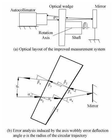
Fig. 3(a) illustrates the improved measurement system. For the refraction of the optical wedge attached to the end of the shaft and the reflection of the mirror fixed on the optical table, the beam from the autocollimator will return with a deflection angle φ after the reflection of mirror, which ensures the spot still moves around the circular trajectory when the shaft rotates. As shown in Fig. 3(a), the spot movement trajectory is also a circle with the angular radius of φ.
|
Figure 3 Analyses of the proposed method |
Bored by the axis wobbly error, the incident angle α of the optical wedge is changed when the optical wedge rotates with the shaft. As shown in Fig. 3(b), the angle α1 is induced by the axis wobbly error and angles αi (i=2-4) and βi (i=1-4) are the corresponding incident or refractive angles. Angle γ is the apex angle of optical wedge. According to the refraction law, the geometric relationship in Fig. 3(b) is given as:
| $ \varphi = {\beta _4}-{\alpha _1} $ | (1) |
| $ \frac{{\sin {\alpha _1}}}{{\sin {\alpha _2}}} = \frac{{\sin {\alpha _4}}}{{\sin {\alpha _3}}} = \frac{{\sin {\beta _1}}}{{\sin {\beta _2}}} = \frac{{\sin {\beta _4}}}{{\sin {\beta _3}}} = n $ | (2) |
| $ {\alpha _3} = {\alpha _2} + \gamma $ | (3) |
| $ {\beta _3} = \gamma-{\beta _2} $ | (4) |
| $ -{\beta _1} + \gamma = {\alpha _4}-\gamma $ | (5) |
where n is the refractive index of the optical wedge. If the axis wobbly error is zero, the beam will pass the optical wedge perpendicularly. When the beam comes back to the autocollimator again, according to the approximate relationship sin γ ≅ γ, the deflection angle is:
| $ \varphi = 2\left( {n-1} \right)\gamma $ | (6) |
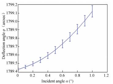
Based on Eq. (6), we can estimate the value γ at the given measurement range of autocollimator. We use the double wedges compensator to get the needed angle γ. The parameters are shown in Table 1. According to the index, we set apex angle γ as 0.485°. Fig. 4 presents the relationship between the axis wobbly error and the deflection angle φ for different incident angle α. The error bars show the change of the deflection angle φ.
| Table 1 The simulation parameters |
|
Figure 4 The effect of the axis wobbly error on the deflection angle φ |
Although the change of the deflection angle φ increases with the incident angle α, its value is always very small. Only ±0.08 arcsec is changed although the incident angle α comes up to 1° when the axis wobbly error is ±100 arcsec, which is far less than the change in the reflective measurement system. It is clear that the spot deviation caused by the axis wobbly error is decreased significantly and the measurement accuracy is improved. Fig. 4 also implies that the emergent beam of the autocollimator should enter the optical wedge perpendicularly in order to get a good measurement precision.
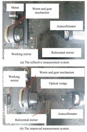
3 Compared ExperimentAs shown in Figs. 5(a) and 5(b), we use the reflective and improved measurement systems to measure the rotation angle error of the worm and gear mechanism in the ADC respectively. The referential mirrors fixed on the optical table are used to eliminate the environmental disturbance. The shaft rotates with a step width 4.5°. Different from the reflective measurement system, the improved measurement system attaches the optical wedge to the end of the hollow shaft and fixes the working mirror on the optical table.
|
Figure 5 The rotation angle error measurement of the worm and gear mechanism |
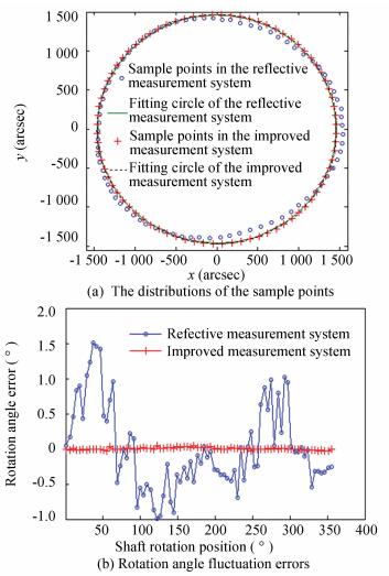
Fig. 6(a) shows the distributions of the sample points in the reflective and proposed measurement systems respectively. The coordinates of the sample points are the ones relative to the center of the fitting circles. Compared with the reflective measurement system, the sample points in the improved measurement system are always on the fitting circle and the distributions of the sample points are uniform, which implies the spot deviations caused by the axis wobbly error is suppressed significantly.
|
Figure 6 Analysis of the measurement results in two measurement systems |
The rotation angle can be expressed as:
| $ {\theta _i} = {\theta _{{\rm{mean}}}} + \Delta {\theta _i} $ | (7) |
where θmean is the mean value of the rotation angle on all measurement process, Δθi is the rotation angle error in per step. The maximal Δθi is the shaft rotation error. According to the coordinates of the sample points and Eq. (7), the fluctuation errors of the rotation angle are gotten, as shown in Fig. 6(b). The rotation angle errors in the reflective and improved measurement systems are about ±1.5° and ±0.05° respectively. The measurement error in the improved measurement system is decreased ±1.45° and the distribution of the rotation angle fluctuation errors is very close to random distribution, which indicates that the measurement result can express the true behavior of the mechanism. It is clear that the improved measurement system has suppressed the measurement error induced by the axis wobbly error perfectly and improved the measurement accuracy of the rotation angle significantly. According to the parameters of the autocollimator, the measurement accuracy of the measurement system is less than ±0.5 armin. We use the measurement system to measure the rotation angle error of another worm and gear mechanism in the ADC and the result is ±0.07°, which also satisfies the design demand (±0.1°).
4 ConclusionsWe design a rotation angle measurement system to measure the rotation angle error of two worms and gears mechanisms in the atmospheric dispersion corrector (ADC). In the design, we introduce the optical wedge to suppress the terrible measurement error induced by the axis wobbly error, which is demonstrated in the compared experiment. The measurement system not only can measure the shaft rotation angle at any rotation position using a brief algorithm, its optical layout is also very simple. Only an optical wedge and two mirrors are needed besides the autocollimator. The measurement accuracy of the proposed method is less than ±0.5 arcmin. In the measurement of two worms and gears mechanisms in ADC, the rotation angle error are ±0.05° and ±0.07° respectively, which all satisfies the design demand (±0.1°). The proposed measurement system can be also widely used in other engineering fields.
| [1] |
Goncharov A V, Devaney N, Dainty C. Atmospheric dispersion compensation for extremely large telescopes.
Optics Express, 2007, 15(4): 1534-1542.
DOI:10.1364/OE.15.001534 ( 0) 0)
|
| [2] |
Devaney N, Goncharov A V, Dainty J C. Chromatic effects of the atmosphere on astronomical adaptive optics.
Applied Optics, 2008, 47(8): 1072-1081.
DOI:10.1364/AO.47.001072 ( 0) 0)
|
| [3] |
Bahrami M, Goncharov A V. The achromatic design of an atmospheric dispersion corrector for extremely large telescopes.
Optics Express, 2011, 19(18): 17099-17113.
DOI:10.1364/OE.19.017099 ( 0) 0)
|
| [4] |
Egner S, Ikeda Y, Watanabe M, et al. Atmospheric dispersion correction for the Subaru AO system.
SPIE, 2010, 7736(4): 77364V-77364V.
( 0) 0)
|
| [5] |
Jin J, Zhao L, Xu S. High-precision rotation angle measurement method based on monocular vision.
Journal of the Optical Society of America A, 2014, 31(7): 1401-1407.
DOI:10.1364/JOSAA.31.001401 ( 0) 0)
|
| [6] |
Lu Weiguo, Wu Yinming, Gao Limin, et al. Rapid measurement of spatial azimuth by using polarized light.
Optics and Precision Engineering, 2013, 21(3): 539-545.
DOI:10.3788/OPE. ( 0) 0)
|
| [7] |
Yun H G, Kim S H, Jeong H S, et al. Rotation angle measurement based on white-light interferometry with a standard optical flat.
Applied Optics, 2012, 51(6): 720-725.
DOI:10.1364/AO.51.000720 ( 0) 0)
|
| [8] |
Wang Xuanze, Zhai Zhongsheng, Zhong Yuning, et al. Measurement of two-dimensional angle using dynamic modulation and interference fringe shape.
Optics and Precision Engineering, 2014, 22(2): 274-280.
DOI:10.3788/OPE. ( 0) 0)
|
| [9] |
Liu Y, Kuang C, Ku Y. Small angle measurement method based on the total internal multi-reflection.
Optics & Laser Technology, 2012, 44(5): 1346-1350.
DOI:10.1016/j.optlastec.2011.12.032 ( 0) 0)
|
| [10] |
Wang Yang, Yan Changxiang, Hu Chunhui, et al. Non-contact rotation angle measurement system for scanning mirrors.
Optics and Precision Engineering, 2014, 22(4): 850-855.
DOI:10.3788/OPE. ( 0) 0)
|
| [11] |
Qiu Zurong, Chen Haoyu, Hu Wenchuan, et al. Embedded angle vision inspection and error compensation for line structured lights.
Optics and Precision Engineering, 2013, 21(10): 2480-2487.
DOI:10.3788/OPE. ( 0) 0)
|
| [12] |
Lu Rongsheng, Li Wanhong, Lao Dabao, et al. Angular error compensation for laser tracker.
Optics and Precision Engineering, 2014, 22(9): 2299-2305.
DOI:10.3788/OPE. ( 0) 0)
|
| [13] |
Gao M, Dong Z, Bian Z, et al. Robust CCD photoelectric autocollimator for outdoor use.
Chinese Optics Letters, 2011, 9(9): 091201.
DOI:10.3788/COL ( 0) 0)
|
| [14] |
Gao Y, Wang X, Hu C, et al. Highly precise micro torsion angle detection by fringe array.
Chinese Optics Letters, 2014, 12(8): 080401.
DOI:10.3788/COL ( 0) 0)
|
| [15] |
Liu Yong, Sun peng, Liu Lishuang, et al. A roll angle measurement method based on dual CCDs.
Optical Technology, 2013, 39(5): 477-480.
( 0) 0)
|
| [16] |
Hao Wenxia, Liu Yong, Li Xiaoying, et al. High-precision roll angle mesurement method based on collimated beams.
Journal of Applied Optics, 2014, 2(2): 281-285.
( 0) 0)
|
| [17] |
Nazarov V N, Sokolov Y A. New method of diffraction monitoring of small angular and linear displacements.
Journal of Optical Technology, 2013, 80(12): 756-760.
DOI:10.1364/JOT.80.000756 ( 0) 0)
|
| [18] |
Konyakhin I A, Turgalieva T V. Three-coordinate digital autocollimator.
Journal of Optical Technology, 2013, 80(12): 772-777.
DOI:10.1364/JOT.80.000772 ( 0) 0)
|
| [19] |
Moiseeva A, Konyakhin I, Kleshchenok M. Investigation of optical-electronic autocollimator with quadrangular pyramidal reflector for measuring the angular position of the object. Latin America Optics and Photonics Conference Cancun: Optical Society of America. 2014. LTh4A. 49. DOI: 10.1364/LAOP.2014.LTh4A.46.
( 0) 0)
|
 2017, Vol. 24


