2. Graduate School of the Chinese Academy of Science, Beijing 100084, China;
3. Key Laboratory of Airborne Optical Imaging and Measurement, Chinese Academy of Science, Changchun 130033, China
For decades, Charge Coupled Devices (CCD) have seen their absolute dominance in the imaging device market, especially in the field of aerial camera. In comparison, CMOS has a number of advantages over CCD, such as low cost and high speed. More importantly, CMOS can be integrated on chips. In the market of consumer-level cameras (e.g. PC cameras, cellphone cameras and high-quality digital cameras), CMOS has already taken the place of CCD[1-2]. However, large frame CMOS has seen very slow development in the field of aerial camera. The main reason is that CMOS leads to geometric distortions in the imaging procedure.
Different from CCD with the global shutter, CMOS often adopts the electronic rolling shutter (RS). Each row of a CMOS is exposed at different time intervals. Therefore a fast relative motion between a camera and an object scene results in image distortions, which is called RS effect or jelly effect. As a result, a CMOS aerial camera imaging at a high speed is subject to severe loss of image quality. Furthermore, this problem is exacerbated when gesture angles (pitch, roll, and yaw) of the aerial camera change. Since the velocity of each pixel is closely related to the pixel's location, the distortion of the whole pixel array is made exceedingly complicated.
In literatures, a large number of vision-based algorithms for rectification of RS distortion exist. Liang et al.[3] proposed an algorithm to address the problem of continuous movement under the assumption of planar motion. After the global motion estimation, curve interpolation is used to remove RS distortion. Cho et al.[4] expressed the translation between consecutive frames with a global affine model and the model could deal with more complicated distortions. Sun et al.[5] proposed an algorithm that performs curve interpolation for each pixel based on optical flow computation. Considering the practical motion situation, Forssen and Ringaby[6-7] proposed a 3D rotation model whose parameters can be obtained by the inter-frame motion estimation. Based on the 3D model above, Hanning et al.[8] rectified and stabilized video sequences by using inertial measurement sensors in mobile phones. All methods mentioned above are based on the motion estimation of consecutive frames under different models. However, the estimation process has a high computational complexity, which eliminates its use in aerial real-time imaging. Another drawback of these algorithms is that they only address the problem of sequential frames in videos and are unable to deal with single frame distortion.
Until recently, nearly all vision-based algorithms are focused on distortion removal for hand-held devices and no theoretical analysis of CMOS distortion in aerial imaging has been made. In order to expand the application of CMOS in the field of aerial camera, we propose a mathematical model to quantitatively calculate the RS effect in aerial imaging for the first time. The coordinate transformation method is used to directly calculate the motion vector of each pixel when the camera is imaging at arbitrary gesture angles. The proposed method skips the motion estimation process between consecutive frames, therefore it can address the problem of single frame distortion.
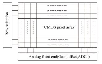
2 Principle of Rolling Shutter EffectThe structure of a typical CMOS sensor is shown in Fig. 1. With a singular readout circuit, only one row can be selected by the row selection signal in each readout period. Then the charges of the selected row are transferred to the signal amplify unit and the analog-to-digital converter (ADC) before readout. Different from CCD in which all pixels are read out simultaneously, rows of CMOS are read out sequentially. And a row cannot be reset or exposed until the first row in RS is read out[9-10].
|
Figure 1 Typical structure of CMOS image sensors |
The working principle of RS is similar to that of a mechanical focal plane shutter. The curtain speed is decided by the readout time of each row. Therefore, when there is a fast relative motion between a CMOS camera and an object scene, the image will be distorted. As shown in Fig. 2, a circle is imaged with the skew distortion resulted from horizontal motion, where ΔT=Ti+1-Ti(i=1, 2, …, 6) denotes the readout time of each row[2, 11]. The severity of RS distortion is relative to the speed of relative motion and the readout time of each row. In order to remove geometric distortions caused by RS, the imaging time of all pixels needs to be rectified to the same reference time.

|
Figure 2 Illustration of rolling shutter distortion caused by horizontal motion |
3 Modeling of Rolling Shutter Effect in Aerial Imaging
Compared with that of hand-held CMOS cameras, the motion information of aerial cameras can be obtained precisely from an inertial navigation system and further used to calculate motion vectors of all pixels directly. With pixel's velocity obtained, the distortion of each pixel can be calculated and used for rectification in turn.
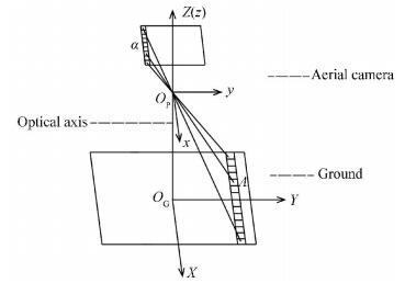
3.1 Calculation of Pixel's VelocityBefore analyzing the RS effect, the velocity of each pixel needs to be calculated when an aircraft flies at arbitrary gesture angles. In the photogrammetry, object points can be transformed to image points following a series of coordinate transformations[12]. As the camera is fixed on the aircraft, we make no distinction between the coordinate system of image sensor and that of aircraft. In addition, rather the relative coordinates than the absolute coordinates are concerned in terms of the velocities of pixels. Therefore, only two coordinate systems are taken into account: the geographical coordinate system and the aircraft coordinate system. These two coordinate systems are defined as follows and both of them follow the right-hand rule as shown in Fig. 3[13-14].
|
Figure 3 Definitions of coordinate systems at initial time |
(1) Geographical coordinate system G: the origin is defined as the intersection point of the optical axis and the ground at initial time. The Y axis is parallel to the flight direction. Meanwhile, the Z axis is vertical to the ground and points toward the sky.
(2) Aircraft coordinate system P : the origin is the projection center of the aerial camera. Before the gesture angles change, three axes of P are parallel to the axes of G, where x is the pitching axis, y is the rolling axis, and z is the yawing axis. Moreover, x is parallel to the readout direction of CMOS and y is vertical to the readout direction.
It is assumed that the change order of gesture angles is as follows: the aircraft first changes its rolling angle around y, then its pitching angle around x, and finally its yawing angle around z. The CMOS camera changes positions according to these changes in gesture angles.
According to the definitions above, in the aircraft coordinate system, the coordinate of an arbitrary point a in the CMOS is given by (x, y, f), corresponding to an object point A denoted by the coordinate (X, Y, 0) in the geographical coordinate system. Through coordinate transformations, the image point a, the object point A and the origin OP are made to lie on a same straight line in the sensor coordinate system. This line can be described as[15-17]:
| $ \left( {\begin{array}{*{20}{c}} {x-{x_p}}\\ {y-{y_p}}\\ {f-{z_p}} \end{array}} \right) = \lambda \mathit{\boldsymbol{R}}\left( {\begin{array}{*{20}{c}} {X - {X_p}}\\ {Y - {Y_p}}\\ {0 - {Z_p}} \end{array}} \right) $ | (1) |
where λ is the linear coefficient, f is the camera's focal length, and R represents the coordinate rotation. (xp, yp, zp) gives the coordinate of OP in the aircraft coordinate system, and (Xp, Yp, Zp) gives the corresponding geographical coordinate. And they can be written as:
| $ \begin{array}{l} \mathit{\boldsymbol{R}} = {\mathit{\boldsymbol{R}}_\mathit{\boldsymbol{\beta }}}{\mathit{\boldsymbol{R}}_\mathit{\boldsymbol{\alpha }}}{\mathit{\boldsymbol{R}}_\mathit{\boldsymbol{\gamma }}} = \left( {\begin{array}{*{20}{c}} {\cos \beta }&0&{-\sin \beta }\\ 0&1&0\\ {\sin \beta }&0&{\cos \beta } \end{array}} \right) \cdot \\ \;\;\;\;\;\;\;\;\;\left( {\begin{array}{*{20}{c}} 1&0&0\\ 0&{\cos \alpha }&{\sin \alpha }\\ 0&{-\sin \alpha }&{\cos \alpha } \end{array}} \right)\left( {\begin{array}{*{20}{c}} {\cos \gamma }&{\sin \gamma }&0\\ {-\sin \gamma }&{\cos \gamma }&0\\ 0&0&1 \end{array}} \right) \end{array} $ | (2) |
| $ \left( {\begin{array}{*{20}{c}} {{x_p}}\\ {{y_p}}\\ {{z_p}} \end{array}} \right) = \left( {\begin{array}{*{20}{c}} 0\\ 0\\ 0 \end{array}} \right), \left( {\begin{array}{*{20}{c}} {{X_p}}\\ {{Y_p}}\\ {{Z_p}} \end{array}} \right) = \left( \begin{array}{l} 0\\ {V_s}t\\ H \end{array} \right) $ | (3) |
where Vs is the flight speed, and H is the flight height. α, β and γ denote the angles of pitching, rolling and yawing, respectively.
Taking the matrix transformations of Eq. (1) yields,
| $ \begin{array}{l} \left( {\begin{array}{*{20}{c}} {\cos \gamma }&{-\sin \gamma }&0\\ {\sin \gamma }&{\cos \gamma }&0\\ 0&0&1 \end{array}} \right)\left( {\begin{array}{*{20}{c}} 1&0&0\\ 0&{\cos \alpha }&{-\sin \alpha }\\ 0&{\sin \alpha }&{\cos \alpha } \end{array}} \right) \cdot \\ \;\;\;\;\;\;\;\;\;\;\left( {\begin{array}{*{20}{c}} {\cos \beta }&0&{\sin \beta }\\ 0&1&0\\ {-\sin \beta }&0&{\cos \beta } \end{array}} \right)\left( \begin{array}{l} x\\ y\\ f \end{array} \right) = \lambda \left( {\begin{array}{*{20}{c}} X\\ {Y - {V_s}t}\\ { - H} \end{array}} \right) \end{array} $ | (4) |
Then the solution of λ is:
| $ \lambda = \frac{1}{H}\left( {x\cos \alpha \sin \beta-y\sin \alpha-f\cos \alpha \cos \beta } \right) $ | (5) |
The analytical equation of pixel's velocity is obtained via a differential operation on Eq. (1), which can be described as
| $ \mathit{\boldsymbol{V = }}\frac{{{\rm{d}}\mathit{\boldsymbol{x}}}}{{{\rm{d}}t}} = {V_x}\left( {x, y} \right)\mathit{\boldsymbol{i + }}{V_y}\left( {x, y} \right)\mathit{\boldsymbol{j}} $ | (6) |
where x =(x, y, f)T. Denote X = (X, Y-Vst, -H) T, and Eq. (1) can be rewritten as an expression of x and y. After differentiation with respect to t, it can be arranged as
| $ {\left( {\frac{{{\rm{d}}x}}{{{\rm{d}}t}}, \frac{{{\rm{d}}y}}{{{\rm{d}}t}}} \right)^{\rm{T}}} = {\left( {{V_x}, {V_y}} \right)^{\rm{T}}} = \mathit{\boldsymbol{MR}}\frac{{{\rm{d}}\mathit{\boldsymbol{X}}}}{{{\rm{d}}t}} $ | (7) |
where
| $ \mathit{\boldsymbol{M}} = \left( {\begin{array}{*{20}{c}} \lambda &0&{\lambda x/f}\\ 0&\lambda &{\lambda y/f} \end{array}} \right) $ | (8) |
The solutions to Eq. (6) are given by:
| $ \left\{ \begin{array}{l} {V_x} =- \frac{{\lambda {V_s}}}{f}\left[{f\left( {\cos \beta \sin \gamma + \sin \alpha \sin \beta \cos \gamma } \right) + } \right.\\ \;\;\;\;\;\;\left. {x\left( {\sin \beta \sin \gamma-\sin \alpha \cos \beta \cos \gamma } \right)} \right]\\ {V_y} = -\frac{{\lambda {V_s}}}{f}\left( {f\cos \alpha \cos \gamma + y\sin \beta \sin \gamma -y\sin \alpha \cos \beta \cos \gamma } \right) \end{array} \right. $ | (9) |
If the change order of gesture angles or the definition of coordinate systems differs from what introduced in this paper, the velocity expression of CMOS array differs as well. Since it can be obtained through the process above, discussions regarding this issue are needless here.
3.2 Modeling of Rolling Shutter EffectThe distortion caused by RS is related to the velocity direction and it can be classified into two categories: one is the distortion caused by the motion parallel to the readout direction, namely horizontal motion; the other is the distortion caused by the motion vertical to the readout direction, namely vertical motion. These two types of distortion are independent of each other and can be analyzed separately[18].
Under the assumption of uniform velocity, Chun et al.[19] analyzed the distortion resulted from horizontal or vertical motion. On the basis of their results, the distortion caused by the aviation flight at arbitrary gesture angles is further calculated. Assuming the readout time of each row is short enough that the velocity during readout can be regarded as constant. The size of the image sensor is M×N and the pixel size is d.
3.2.1 Horizontal motionWhen the image sensor moves along the readout direction at speed Vx, the distance it moves per unit time can be written as Vx/d pixels. As each row is exposed slightly later than the previous row, the distance each row moves increases from top to bottom, which leads to the skewing distortion.
To denote the readout time of each row as tr, then the k-th row has a readout time of (k-1)tr. For an arbitrary point (x, y) (here we consider only the sensor plane and ignore the z axis), it is located in the (N/2-y) row according to the aircraft coordinate system. Therefore the distortion caused by horizontal motion can be obtained with the equation below
| $ {d_{x, a}} = \int_0^{\left( {N/2-y-1} \right){t_r}} {\frac{{{V_x}}}{d}{\rm{d}}t} = {V_x}{t_r}\left( {N/2-y - 1} \right)/d $ | (10) |
When the image sensor moves along the vertical readout direction at speed Vy, either of two cases as described below may occur: in one case the sensor moves in the same direction with the RS, where a portion of rows are double-exposed, causing the stretch distortion in final images. In the other case the sensor moves in the direction opposite to the RS, which shrinks final images.
The same as in the previous section, considering an arbitrary point (x, y) located in the (N/2-y) row. Denoting the vertical distortion as dy, a. According to the conclusion in Ref. [19], it can be written as
| $ {d_{y, a}} = \frac{{{V_y}\left( {N/2-y-1} \right)}}{{d\left( {1/{t_r}-{V_y}/d} \right)}} = \frac{{{V_y}{t_r}\left( {N/2 - y - 1} \right)}}{{d - {V_y}{t_r}}} $ | (11) |
As Vytr≪d, the final distortion of an arbitrary point a can be given by
| $ \left\{ \begin{array}{l} {d_{x, a}} =- \frac{{\lambda {V_s}{t_r}\left( {N/2- y- 1} \right)}}{{fd}}\\\left[{f\left( {\cos \beta \sin \gamma + \sin \alpha \sin \beta \cos \gamma } \right) + x\left( {\sin \beta \sin \gamma-\sin \alpha \cos \beta \cos \gamma } \right)} \right]\\ {d_{y, a}} = -\frac{{\lambda {V_s}{t_r}\left( {N/2 -y -1} \right)}}{{fd}}\left( {f\cos \alpha \cos \gamma + y\sin \beta \sin \gamma - y\sin \alpha \cos \beta \cos \gamma } \right) \end{array} \right. $ | (12) |
Eq. (12) demonstrates that the pixel distortion caused by horizontal or vertical motion differs from each other and is closely related to the pixel's location. Therefore the problem to rectify RS distortion is very complicated and no mechanism can correct the distortion accurately. To obtain high-quality aerial images, the distortion rectification should be made based on this mathematical model.
4 Experimental ResultsIn this chapter, a series of experiments are designed to simulate aerial imaging at different speeds and gesture angles. Limited by our experimental conditions two of the gesture angles, namely the pitching and rolling angles, are taken into account, and the yawing angle is set to zero. For this reason, Eq. (12) can be rewritten as
| $ \left\{ \begin{array}{l} {d_{x, a}} =-\frac{{\lambda {V_s}{t_r}\left( {N/2-y-1} \right)}}{{fd}}\left( {f\sin \alpha \sin \beta - } \right.\\ \;\;\;\;\;\;\;\;\left. {x\sin \alpha \cos \beta } \right)\\ {d_{y, a}} = - \frac{{\lambda {V_s}{t_r}\left( {N/2 - y - 1} \right)}}{{fd}}\left( {f\cos \alpha - y\sin \alpha \cos \beta } \right) \end{array} \right. $ | (13) |
As illustrated in Fig. 4, the experimental platform mainly consists of a CMOS camera, a linear displacement stage, a motion controller, a two-dimensional turntable and a data collection terminal. And all of the equipment is kept horizontal on a vibration isolation platform.

|
Figure 4 Experimental platform |
The distance between the CMOS camera and the object scene is constant and we use the linear displacement stage to control the V/H ratio by changing the camera's speed. Meanwhile the gesture angles are adjusted with the two-dimensional turntable. Firstly we keep the V/H invariant and change the gesture angles. Then we keep the gesture angles invariant and change the camera's speed. Therefore a series of images with different distortions are obtained to validate our model. Key parameters of the simulated aerial camera are shown in Table 1.
| Table 1 Key parameters of the simulated aerial camera |
4.1 Effect of the Measuring Errors
Firstly the effect of measuring errors in the experiment is discussed here. According to Eq. (12), main errors come from the V/H ratio and gesture angles. In order to analyze the effect of changes of V/H ratio and gesture angles on distortion errors, we use the total differential method to implement an error synthesis. The expression of the composite error is given below.
| $ {\sigma _d} = \sqrt {{{\left( {\frac{{\partial d}}{{\partial \eta }}} \right)}^2}\sigma _\eta ^2 + {{\left( {\frac{{\partial d}}{{\partial \alpha }}} \right)}^2}\sigma _\alpha ^2 + {{\left( {\frac{{\partial d}}{{\partial \beta }}} \right)}^2}\sigma _\beta ^2} $ | (14) |
where η=V/H and ση, σα, σβ represent the standard deviation of η, the pitching angle and the rolling angle, respectively. σd represents the composite error of dx, a or dy, a.
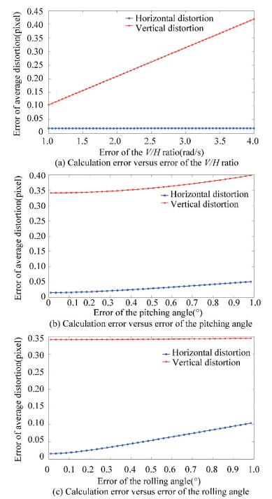
According to the actual measurement process, the standard deviation of V changes from 0.1 mm/s to 0.2 mm/s and the standard deviation of H changes from 0.05 m to 0.1 m. Therefore the margin of ση is 0.001-0.004 and the final error curve of average distortion over the whole CMOS array versus the change of ση is shown in Fig. 5(a). Meanwhile, the measuring errors of gesture angles are less than 1°. Figs. 5(b) and 5(c) illustrate the error curve of average distortion versus the error change of gesture angels. Here it should be stated that when analyzing one of the measuring errors, the others are set to the maximum values.
|
Figure 5 Calculation error of our model versus the change of the measuring errors |
In Fig. 5, we note that with the increase of measuring errors, the final distortion errors have only slight change and are less than 1/2 pixel. At the same time, it indicates that the vertical distortion is much larger than the horizontal distortion and must be taken as a priority in practice. The analysis demonstrates that the accuracy of our model meets the requirements of this experiment. Furthermore, it meets the needs of aerial imaging which requires more accurate measurement results.
4.2 Rectification of Distorted ImagesAfter capturing different distorted images, the motion information in them is obtained at the same time. According to Eq. (13), the distortion map of the whole CMOS array is calculated, which illustrates the distortion of every pixel. Then the distorted images can be rectified by the reverse projection. The overall flow chart of our method is shown in Fig. 6.

|
Figure 6 Block diagram of the proposed method |
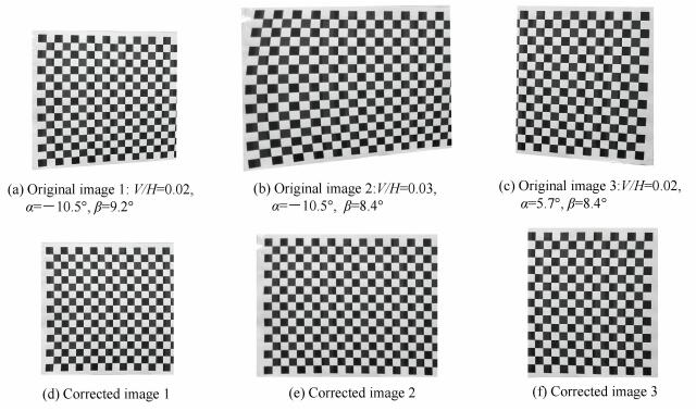
Three representative groups of experimental results are shown in Fig. 7. The original images with different levels of distortion are at the top and the corrected images via our model are at the bottom. As shown in Fig. 7, with the increase of V/H ratio, the distortion in Fig. 7(b) is more serious than that in Fig. 7(a). And when the camera is imaging at different gesture angles, the distortions present several forms closely related to the pixel's velocity at the time. All distortions are removed successfully.
|
Figure 7 Rectification of different distorted images |
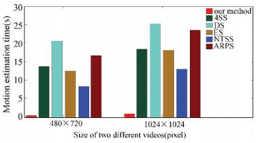
To further explain the efficiency of the calculation model, we capture videos of different frame sizes using two RS cameras, and compare the motion estimation time of several block matching algorithms with the calculation time of our model. The results are shown in Fig. 8, where Four Step Search (4SS), Diamond Search (DS), Exhaustive Search (ES), New Three Step Search (NTSS), and Adaptive Rood Pattern Search (ARPS) are different block matching algorithms arranged by Aroh[20]. And the block size in the computation is 4×4.
|
Figure 8 Comparison of the computation time of motion estimation on two differently-sized videos |
5 Conclusions
In this paper we propose a mathematical model which is obtained via coordinate transformations for removal of RS distortion in aerial imaging. Unlike vision-based algorithms based on the inter-frame motion estimation, the proposed method calculates the pixel distortion directly and addresses the problem of single frame distortion. The error analysis indicates that the calculation error of our model is less than 1/2 pixel for all measuring errors, which guarantees the accuracy of rectification. Finally, a series of experimental results demonstrate the validity of our model. The comparison of calculation time shows that our method is ten times faster than the vision-based algorithms, which makes it more suitable for aerial real-time imaging.
| [1] |
EL Gamal A, Eltoukhy H. CMOS image sensors.
IEEE Circuits & Devices Magazine, 2005, 21(3): 6-20.
( 0) 0)
|
| [2] |
Junichi N.
Image Sensors and Signal Processing for Digital Still Cameras. Abingdon: CRC Press of Taylor & Francis Group, 2006.
( 0) 0)
|
| [3] |
Liang Chiakai, Chang Liwen, Chen Horner H. Analysis and compensation of rolling shutter effect.
IEEE Transactions on Image Processing, 2008, 17(8): 1323-1330.
DOI:10.1109/TIP.2008.925384 ( 0) 0)
|
| [4] |
Cho Wonho, Hong Kisang. Affine motion based CMOS distortion analysis and CMOS digital image stabilization.
IEEE Transactions on Consumer Electronics, 2007, 53(3): 833-841.
DOI:10.1109/TCE.2007.4341553 ( 0) 0)
|
| [5] |
Sun Yufen, Liu Gang. Rolling shutter distortion removal based on curve interpolation.
IEEE Transactions on Consumer Electronics, 2012, 58(3): 1045-1050.
DOI:10.1109/TCE.2012.6311354 ( 0) 0)
|
| [6] |
Forssén Per-Erik, Ringaby Erik. Rectifying rolling shutter video from hand-held devices.
Proceedings of the IEEE Conference on Computer Vision and Pattern Recognition.Piscataway:IEEE, 2010: 507-514.
DOI:10.1109/CVPR.2010.5540173 ( 0) 0)
|
| [7] |
Ringaby Erik, Forssén Per-Erik. Efficient video rectification and stabilisation for cell-phones.
International Journal of Computer Vision, 2012, 96(3): 335-352.
DOI:10.1007/s11263-011-0465-8 ( 0) 0)
|
| [8] |
Hanning Gustav, Forslow Nicklas, Forssen Per-Erik, et al. Stabilizing cell phone video using inertial measurement sensors.
Proceedings of the IEEE International Conference on Computer Vision Workshops, ICCV 2011 Workshops, Piscataway:IEEE, 2011: 1-8.
DOI:10.1109/ICCVW.2011.6130215 ( 0) 0)
|
| [9] |
Jia Chao, Evans Brian L. Probabilistic 3-D motion estimation for rolling shutter video rectification from visual and inertial measurements.
IEEE International Workshop on Multimedia Signal Processing, Piscataway:IEEE, 2012: 203-208.
DOI:10.1109/MMSP.2012.6343441 ( 0) 0)
|
| [10] |
Kim Young-Geun, Jayanthi Venkata Ravisankar, Kweon In-So. System-on-chip solution of video stabilization for CMOS image sensors in hand-held devices.
IEEE Transactions on Circuits and Systems for Video Technology, 2011, 21(10): 1401-1414.
DOI:10.1109/TCSVT.2011.2162764 ( 0) 0)
|
| [11] |
Zhen Ruiwen, Stevenson Robert L. Semi-blind deblurring images captured with an electronic rolling shutter mechanism.
Proceedings of SPIE-The International Society for Optical Engineering 9410.Bellingham:SPIE, 2015: 941003-1.
DOI:10.1117/12.2077262 ( 0) 0)
|
| [12] |
Zhao Jiaxin, Zhang Tao, Yang Yongming, et al. Image motion velocity filed of TDI-CCD aerial panoramic camera.
Acta Optica Sinca, 2014, 34(7): 0728003.
DOI:10.3788/AOS201434.0728003.(inChinese) ( 0) 0)
|
| [13] |
Hu Yan, Jin Guang, Chang Lin, et al. Image motion matching calculation and imaging validation of TDI CCD camera on elliptical orbit.
Optics and Precision Engineering, 2014, 22(8): 2274-2284.
DOI:10.3788/OPE.20142208.2274.(inChinese) ( 0) 0)
|
| [14] |
Zhou Qianfei, Liu Jinghong. Automatic orthorectification and mosaicking of oblique images from a zoom lens aerial camera.
Optical Engineering, 2015, 54(1): 013104.
DOI:10.1117/1.OE.54.1.013104 ( 0) 0)
|
| [15] |
Ghosh Sanjib K. Image motion compensation through augmented collinearity equations.
Proceedings of the SPIE 0491, 16th Intl Congress on High Speed Photography and Photonics. Bellingham:SPIE, 1985, 491: 837-842.
DOI:10.1117/12.968023 ( 0) 0)
|
| [16] |
Liu Zhiming, Zhu Ming, Chen Li, et al. Long range analysis and compensation of smear in sweep aerial remote sensing.
Acta Optica Sinca, 2013, 33(7): 0711001.
DOI:10.3788/AOS201333.0711001.(inChinese) ( 0) 0)
|
| [17] |
Wu Xingxing, Liu Jinguo. Image motion compensation of scroll imaging for space camera based on earth ellipsoid.
Optics and Precision Engineering, 2014, 22(2): 351-359.
DOI:10.3788/OPE.20142202.0351.(inChinese) ( 0) 0)
|
| [18] |
Lee Yun Gu, Kai Guo. Fast-rolling shutter compensation based on piecewise quadratic approximation of a camera trajectory.
Optical Engineering, 2014, 53(9): 093101.
DOI:10.1117/1.OE.53.9.093101 ( 0) 0)
|
| [19] |
Chun Jung-Bum, Jung Hunjoon, Kyung Chong-Min. Suppressing rolling-shutter distortion of CMOS image sensors by motion vector detection.
IEEE Transactions on Consumer Electronics, 2008, 54(4): 1479-1487.
DOI:10.1109/TCE.2008.4711190 ( 0) 0)
|
| [20] |
Aroh B. Block matching algorithms for motion estimation.
IEEE Transactions Evolution Computation, 2004, 8: 225-239.
DOI:10.1109/TEVC.2004.826069 ( 0) 0)
|
 2017, Vol. 24


