2. University of Chinese Academy of Sciences, Beijing 100039, China
With the development of the mechanical design and control strategy, several large aperture ground based optical telescopes have been built in the world. These telescopes are facing the same challenge of the image jitter during observing. The measurement result of the jitter performance for the Pan-Starr 2 telescope is less than 20 milliarcseconds RMS[1]. The VLTI Auxiliary telescope is located on the Cerro Paranal in Chile, in order to improve the disturbance rejection and the system image quality property, the servo system of the telescope uses an acceleration feedback control in addition to the position and velocity control[2]. The jitter requirement for the Hubble Space Telescope must be less than 7 milliarcseconds RMS in order to avoid reducing the image quality[3].
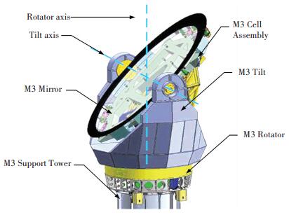
The thirty meter telescope (TMT) is a large aperture Ritchey-Chrétien three mirror design telescope which is being built in Hawaii. The primary mirror is composed with 492 hexagonally-shaped segments. The secondary mirror system is mounted on the top of the mechanical structure with an aperture of 3.1 m. The tertiary mirror system is designed for the control of the optical beam coming from the secondary mirror to the active scientific instrument on the Nasmyth platform, it consists of an elliptical flat mirror, and the size of the mirror is 2.5 by 3.5 m[1, 4]. This extremely large ground based telescope is developing by a way of international cooperation. The tertiary mirror system of the thirty meter telescope is designed by Changchun Institute of Optics, Fine Mechanics and Physics, Chinese Academy of Sciences. The main challenge for the system is the extremely high image jitter requirement during guiding. The concept design of the tertiary mirror system is shown in Fig. 1.
|
Figure 1 TMT tertiary mirror system |
Jitter is defined as the image position motion during the telescope observing. The design of the mechanical structure can affect the telescope pointing performance.In order to obtain a high quality observing result, the image jitter of the tertiary mirror system is considered as an important factor in the design of the TMT system. In this paper, a jitter test experiment has been done to support the design of the TMT tertiary mirror system. The testing telescope is extremely similar with the tertiary mirror system in size and hardware selection. According to the experimental result, the position tracking jitters are analyzed under several low velocities, and the power spectral allocation are presented. These experimental results are valuable to direct the analysis and design of the tertiary mirror system, and also can reach an aim of verifying the image jitter performance[5-7].
The arrangement for the remaining of this paper is as follows:the first part describes the disturbance sources and then describes the testing experiment and investigates the system jitter in detail. The next part covers the jitter test results and the characteristics analysis. Lastly, some conclusions and discussion are shown.
2 Disturbance SourcesThe tertiary mirror system should be operated smoothly during observing. In order to obtain a high quality image, it is particularly significant to analyze the disturbance sources and know what is causing jitter, since it may cause serious problem. Researchers and engineers of the large aperture telescope allocate the image jitter into several sources based on their investigation for many years: Structural vibration; Motor torque ripple; Bearing friction; Encoder resolution; Wind load. Wind excitation and the vibration affects the image performance of the telescope structure system. Other sources are caused by the motion drive system[8-12].
Fig. 2 is a summary block diagram of the disturbance sources. According to this figure, structure vibration and bearing friction is the main reason for the system image jitter[13-15]. For every disturbance source, the model should be built, and the relevant compensation measurement should be used in order to make the telescope system meet the jitter requirement[16-18].

|
Figure 2 The disturbance sources causing jitter |
3 Testing to Investigate the Rotator System Jitter
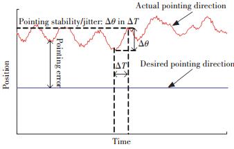
The purpose for the jitter test is to build a system with good performance, in this paper, the test is set up using a high resolution encoder to feedback the velocities during the position tracking mode. The position tracking slope is based on the low velocities.With proper test, the position variation is a direct measurement of the actual axial jitter through the output of the absolute encoder, the measurement result contains not only the effects of the bearing friction and motor torque ripple, but also the vibration of environment and the system structural elements. The jitter specific definition is presented in Fig. 3. Jitter is presented as the peak to peak value of the actual system position within a short time interval, and the pointing error is defined as the difference between the actual system position and the desired position.
|
Figure 3 The definition of pointing jitter |
We select the motor RI17-3P-168×125-WL made by IDAM for this test experiment. Parameters of the drive motor for rotator axis are shown in Table 1.
| Table 1 Parameters of drive motor RI17-3P-168×125-WL |
For the description of the test device, Table 2 shows the detail specifications of the encoder RA32BAA209B50A. The experiment tests the jitter performance of the telescope in the azimuth direction with this 32 bit absolute angle encoder.
| Table 2 Specifications of encoder RA32BAA209B50A |
TMT tertiary mirror system is designed as a direct linear drive of the brushless motor. In order to analyze the axis jitter performance of the tertiary mirror system, a similar configuration telescope is selected to test the jitter and direct the design of the tertiary mirror system, and also can verify that whether or not this kind of design can fit for the low jitter requirement of the tertiary mirror system. The main aim of the test is to reach the jitter error requirement of the tertiary mirror system.
4 Results and the Telescope Jitter Characteristics AnalysisThe jitter of the TMT tertiary mirror system determines of how much shaking will be seen in the final observation image.The tertiary mirror system focuses on the tracking performance under the low velocity. The experiment contains the range of velocities that the telescope requires during observing. The aim of the test is to measure the jitter performance of the telescope. Table 3 shows a detail description of the test requirement, including the low rotation velocity requirement and the tracking jitter requirement.
| Table 3 Telescope rotator test requirement |
According to Table 3, the jitter test has been done under the rotation speed between 0 to 3 600 arcsec/s, including the ultra low tracking speed 0-5 arcsec/s. The tracking jitter requirement should be less than 69 milliarcsec RMS. In this experiment, the telescope is operated under the test velocity in Table 3. According to the final test result, the data analysis for the position tracking jitter is given.
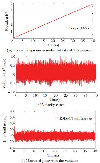
Fig. 4 shows the jitter characteristics analysis based on the position tracking. According to the experimental result, when the position tracking slope is 3.6 arcsec/s, the jitter can reach to 6.7 milliarcsec RMS. The jitter contribution includes the vibration from the structure elements and another reason responding the jitter may be caused by the light weight of the structure, because the test has only been done on the rotator, and the elevation load has not been assembled.
|
Figure 4 The jitter of the position tracking under the velocity of 3.6 arcsec/s |
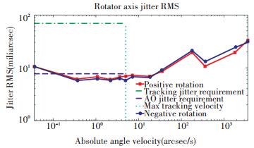
In order to understand if different position tracking speeds and different rotation directions can influence the system jitter response. Fig. 5 shows the RMS jitter values compared with different tracking speeds, where each point is plot corresponding to its position tracking slope, and the measurement results and the corresponding jitter requirements are shown in it. The jitter is less than 30 milliarcsec RMS, however, when the tracking slope is between 0 to 5 arcsec/s, the jitter measurement result is less than 10 milliarcsec RMS.
|
Figure 5 Jitter measurement result for different tracking velocities |
According to the TMT tertiary mirror system design requirement, the motion jitter of the tertiary mirror should be less than 69 milliarcsec RMS during the position tracking. So the experimental result can meet the jitter requirement and can also reach the aim of supporting the design of the tertiary mirror system.
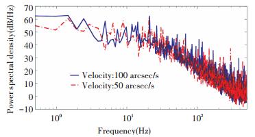
Fig. 6 shows the power spectral distribution of the jitter, and the curves in this figure are based on the tracking speeds of 50 arcsec/s and 100 arcsec/s respectively. According to this frequency distribution, the jitter presented as big amplitudes in the lower frequency range. The system seems to be shaking in this frequency range. The power of the jitter will reduce when the frequency continues to increase. So according to the spectral, the influence coming from the high frequencies can be neglected.
|
Figure 6 The power spectral distribution of the testing jitter |
For the TMT tertiary mirror system, the adaptive optical system can compensate the image jitter within the NFIRAOS instrument, the jitter error is corrected based on the rejection transfer function curve shown in the TMT tertiary mirror system design requirement[19]. The jitter of the tertiary mirror system can be compensated with a high pass filter, the break frequency of the filter is 15 Hz. After the using of this compensation, the jitter occurs at the frequency less than 15 Hz can be corrected and filtered through the NFIRAOS error rejection transfer. The tracking performance of the tertiary mirror system can be improved during observation.
5 ConclusionsIn order to support the design of the TMT tertiary mirror system, an actual jitter test has been done on a telescope. A high resolution absolute angle encoder is used to feedback the real time position of the test platform during the position tracking. According to the measurement result, jitter is analyzed.The jitter is less than 10 milliarcsec RMS under the low tracking speeds which can meet the jitter requirement of the tertiary mirror system. The power spectral analysis of jitter is presented. Then the NFIRAOS error rejection transfer function is given for the tertiary mirror system. The jitter performance of the TMT tertiary mirror system can be further improved after correction.
| [1] |
Ford V, Carter C, Delrez C. Jitter studies for the secondary and tertiary mirror systems on the thirty meter telescope. Proceedings of the SPIE 9151, Advances in Optical and Mechanical Technologies for Telescopes and Instrumentation. Bellingham: SPIE, 2014, 9151: 91512H-1-91512H-15. DOI: 10.1117/12.2055036.
( 0) 0)
|
| [2] |
Sedghi B, Bauvir B, Dimmler M. Acceleration feedback control on an AT. Proceedings of the SPIE 7012, Ground-based and Airborne Telescopes Ⅱ. Bellingham: SPIE, 2008, 7012: 70121Q-1-70121Q-12. DOI: 10.1117/12.789333.
( 0) 0)
|
| [3] |
Bely P Y, Lupie O L, Hershey J H. Line-of-sight jitter of the Hubble Space Telescope. Proceedings of the SPIE 1945, Space Astronomical Telescopes and Instruments Ⅱ. Bellingham: SPIE, 1993, 1945: 55-61. DOI: 10.1117/12.158800.
( 0) 0)
|
| [4] |
An Qichang, Zhang Jingxu, Yang Fei. TMT tertiary mirror axis calibration with laser tracker.
Optoelectronics Letters, 2015, 11(2): 84-87.
DOI:10.1007/s11801-015-5019-9 ( 0) 0)
|
| [5] |
Wang Fuguo, Yang Fei, Zhao Hongchao, et al. Progress in TMT M3 system.
Chinese Optics, 2013, 5(6): 643-651.
DOI:10.3788/co.20130605.0643.(inChinese) ( 0) 0)
|
| [6] |
Yang Xiaoxia, Meng Haoran, Yin Yumei, et al. Jitter measurement for large opto-electronic telescope using accelerometers.
Journal of Electronic Measurement and Instrument, 2013, 9(27): 823-830.
DOI:10.3724/SP.J.1187.2013.00823.(inChinese) ( 0) 0)
|
| [7] |
Yin Guangdong, Wang Jianli, Meng Haoran, et al. Telescope platform jitter measurement and analysis based on accelerometer.
Transducer and Microsystem Technologies, 2013, 11(32): 125-127.
( 0) 0)
|
| [8] |
Pierre Y B.
The Design and Construction of Large Optical Telescopes. Berlin: Springer Verlag, 2003: 34-37.
( 0) 0)
|
| [9] |
David R S, Peter A, Geoff G. Wind-induced structural response of a large telescope. Proceedings of the SPIE 5495, Astronomical Structures and Mechanisms Technology. Bellingham: SPIE, 2004, 5495: 258-269. DOI: 10.1117/12.550465.
( 0) 0)
|
| [10] |
Bentley A E. Pointing control design for a high precision flight telescope using quantitative feedback theory.
International Journal of Robust and Nonlinear Control, 2011, 11(1): 26-29.
DOI:10.1002/rnc.635 ( 0) 0)
|
| [11] |
Gawronski W, Jeffrey A M, Bogusz B. Antenna mean wind torques: a comparison of field and wind-tunnel data.
IEEE Antennas and Propagation Magazine, 2005, 47(5): 55-59.
DOI:10.1109/MAP.2005.1599166 ( 0) 0)
|
| [12] |
Armstrong-Helouvry B. Stick slip and control in low-speed motion.
IEEE Transactions on Automatic Control, 1993, 38(10): 1483-1496.
DOI:10.1109/9.241562 ( 0) 0)
|
| [13] |
Glaese R M, Sheehan M. Vibration mitigation for wind-induced jitter for the giant magellan telescope. Proceedings of SPIE -The International Society for Optical Engineering. Bellingham: SPIE, 2012, 8444: 1-15. DOI: 10.1117/12.926337.
( 0) 0)
|
| [14] |
Vukosavić S N.
Digital Control of Electrical Drives. Berlin: Springer Science & Business Media, 2007: 56-68.
( 0) 0)
|
| [15] |
Gibson S, Tsao T-C T, Herrick D, et al. Adaptive jitter control for tracker line of sight stabilization. Proceedings of the SPIE 7816, Advanced Wavefront Control: Methods, Devices, and Applications Ⅷ. Bellingham: SPIE, 2010, 7816: 78160C-1-78160C8.
http://proceedings.spiedigitallibrary.org/proceeding.aspx?articleid=723570 ( 0) 0)
|
| [16] |
Buttu M, Orlati A, Zacchiroli G, et al. Diving into the Sardinia Radio Telescope minor servo system.
SPIE Software and Cyberinfrastructure for Astronomy Ⅱ, 2012, 8451(2): 1-11.
DOI:10.1117/12.868210 ( 0) 0)
|
| [17] |
Skidmore W, Travouillon T, Riddle R, et al. Experiments at the W. M. Keck Observatory to support the Thirty Meter Telescope design work. Proceedings of the SPIE 7733, Ground-based and Airborne Telescopes Ⅲ. Bellingham: SPIE, 2010, 7733(50): 1-10. DOI: 10.1117/12.857960.
( 0) 0)
|
| [18] |
Adler D S, Kinzel W, Jordan I. Planning and scheduling at STScI: from Hubble to the James Webb Space Telescope. Proceedings of SPIE-The International Society for Optical Engineering. Bellingham: SPIE, 2014, 9149: 1-14. DOI: 10.1117/12.2054932.
( 0) 0)
|
| [19] |
MacMartin D G, Thompson H. Equipment vibration budget for TMT. Proceedings of the SPIE 9145, Ground-based and Airborne Telescopes Ⅴ. Bellingham: SPIE, 2014, 9145: 91452O1-1-91452O-8. DOI: 10.1117/12.2057179.
( 0) 0)
|
 2017, Vol. 24


