Analytical Solution for an Elastic Sphere Indenting a Layered Half-Space
1 Introduction Thin films and coatings have been extensively used in engineering to improve mechanical performance of the solid surfaces. For example, hard coatings can protect parts or tools against wear and abrasion[1-3], and some films are applied as thermal barriers[4-5].
In order to optimize the film/substrate structure design, it is necessary to analyze the mechanical properties of the thin film. It is shown that the indentation test with spherical indenter is an effective method to measure the elastic properties of the coating materials[6-8]. On the other hand, the rough surfaces of solid bodies contain asperities, when two bodies are placed in contact, surface roughness causes contact at discrete summits. The asperity tip is usually assumed to be spherical, the contact problem reduces to a sphere in contact with a flat surface[9]. Therefore, the contact issue between a spherical body and a coated elastic half-space is of great scientific interest.
Yu et al.[10] studied the elastic field of the film/substrate materials caused by the indentations with rigid indenters, and performed the numerical analyses through solving a Fredholm integral equation of the second kind. Jackie Li and Tsu-Wei Chou[11] applying the method of Hankel transforms developed the elastic solution of a layered half space under an axisymmetrical compressive loading. Theoretical solutions showed that the stress field and surface profile are sensitive to the thickness of the coating layer and the ratio of the elastic modulus of the coating material to that of the substrate. Schwarzer et al.[12] constructed the potential functions for a coated half-space indented by a sphere based on the solution of homogeneous half-space under Hertzian Loading. Ogilvy[13] proposed a parametric model which can predict the contact radius for the elastic coating material indented by the spherical indenters. Based on a variational principle Cai and Bhushan[14] investigated the contact behavior of rough, multilayered elastic-perfectly plastic solid surfaces. Applying integral transform method Chen[15] performed an exact analysis of linear elastic stresses and displacements in a half-space with one or two surface layers. Also, some researchers have carried out the numerical analyses using FEM for spherical indentation problems about layered materials[16-17].
The method using the Hankel transforms[10-11] needs to solve complicated integral equations, and it is not convenient to use the numerical results in the indentation test. The final results obtained by Schwarzer et al.[12] are very complex and need heavy computational works. In this study, we present a straightforward methodology to analyze the contact between a sphere and coated half-space based on the fundamental solutions[18] of a concentrated normal force acting on the free surface of a coated material. The solutions are constructed in the form of infinite series. The first term in the solutions is explicit corresponding to the solution of homogeneous half-space under Hertzian loading, and provides main contributions to the stress and displacement.
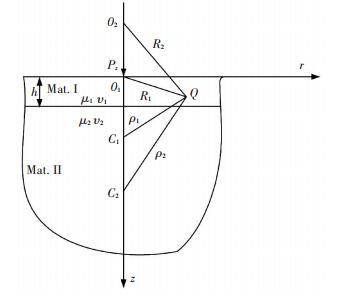
2 Fundamental Solutions for the Coated Half-Space Under a Concentrated Normal Force Fig. 1 shows the cross section of a coated half-space subjected to a concentrated normal force on the surface. The fundamental solutions of this problem can be obtained using the method of image (see details in Ref.[18]). Here, the main procedure and relevant results are briefly described, since the coordinate system is different from that in Ref.[18] so that the forms of stress functions are changed. The origin is set at the free surface instead of interface, and the direction of z-axis is downward. It is convenient using this rearrangement to get the solutions for the contact problem of a sphere indenting a coated half-space. The coating is denoted by material Ⅰ, and the substrate material Ⅱ. μ1, v1 are shear modulus and Poison's ratio of material Ⅰ, and μ2, v2 shear modulus and Poison's ratio of material Ⅱ, respectively.
The problem is spatial axi-symmetric. The general solution can be obtained by two harmonic functions Φ and Ψ as follows[19]:
|
$
2\mu {u_r} = \frac{{\partial \mathit{\Phi }}}{{\partial r}} + z\frac{{\partial \mathit{\Psi }}}{{\partial r}}
$
|
(1) |
|
$
2\mu w = \frac{{\partial \mathit{\Phi }}}{{\partial z}}-\left( {3-4\nu} \right)\mathit{\Psi } + z\frac{{\partial \mathit{\Psi }}}{{\partial z}}
$
|
(2) |
|
$
{\sigma _r} =-\frac{1}{r}\frac{{\partial \mathit{\Phi }}}{{\partial r}}-\frac{{{\partial ^2}\mathit{\Phi }}}{{\partial {z^2}}}-\frac{z}{r}\frac{{\partial \mathit{\Psi }}}{{\partial r}} - z\frac{{{\partial ^2}\mathit{\Psi }}}{{\partial {z^2}}} - 2\nu\frac{{\partial \mathit{\Psi }}}{{\partial z}}
$
|
(3) |
|
$
{\sigma _\theta } = \frac{1}{r}\frac{{\partial \mathit{\Phi }}}{{\partial r}} + \frac{z}{r}\frac{{\partial \mathit{\Psi }}}{{\partial r}}-2\nu\frac{{\partial \mathit{\Psi }}}{{\partial z}}
$
|
(4) |
|
$
{\sigma _z} = \frac{{{\partial ^2}\mathit{\Phi }}}{{\partial {z^2}}}-2\left( {1-\nu} \right)\frac{{\partial \mathit{\Psi }}}{{\partial z}} + z\frac{{{\partial ^2}\mathit{\Psi }}}{{\partial {z^2}}}
$
|
(5) |
|
$
{\tau _{rz}} = \frac{{{\partial ^2}\mathit{\Phi }}}{{\partial r\partial z}}-\left( {1-2\nu} \right)\frac{{\partial \mathit{\Psi }}}{{\partial r}} + z\frac{{{\partial ^2}\mathit{\Psi }}}{{\partial r\partial z}}
$
|
(6) |
where, μ represents shear modulus and ν Poisson's ratio. Shown as Fig. 1 the concentrated loading exerts at point O1, the origin of the coordinate system. In Fig. 1, C1 is the first image of the loading point O1 about the interface, and then the second image O2 is produced by the surface. Consequently, according to the interface and surface an infinite series of image points are generated. The images upon the surface (including the origin at the surface) are represented by Oi with the local coordinates zk. The images blow the interface are Ci with the local coordinates ζk. The distances between the observation point and the image points are as follows:
|
$
\begin{array}{l}
{R_k} = \sqrt {{r^2} + z_k^2}, {z_k} = z + 2\left( {k-1} \right)h\\
{\rho _k} = \sqrt {{r^2} + \zeta _k^2}, {\zeta _k} = z-2kh
\end{array}
$
|
The stress functions are assumed as:
|
$
\begin{array}{l}
{\mathit{\Phi }_{\rm{Ⅰ}}} = \sum\limits_{i = 1}^\infty {{\varphi _i}\left( {r, {z_i}} \right)} + \sum\limits_{i = 1}^\infty {{\beta _i}\left( {r, {\zeta _i}} \right)}, {\mathit{\Phi }_{{\rm{Ⅱ}}}} = \sum\limits_{i = 1}^\infty {{f_i}\left( {r, {z_i}} \right)} \\
{\mathit{\Psi }_{\rm{Ⅰ}}} = \sum\limits_{i = 1}^\infty {{\psi _i}\left( {r, {z_i}} \right)} + \sum\limits_{i = 1}^\infty {{\eta _i}\left( {r, {\zeta _i}} \right)}, {\mathit{\Psi }_{{\rm{Ⅱ}}}} = \sum\limits_{i = 1}^\infty {{g_i}\left( {r, {z_i}} \right)}
\end{array}
$
|
The subscripts 'Ⅰ' and 'Ⅱ" represent the film and substrate, respectively. Namely, the stress functions ΦⅠ, ΨⅠ correspond to material 'Ⅰ', the film, and ΦⅡ, ΨⅡ to material 'Ⅱ", the substrate. Continuity conditions at the interface:
|
$
\begin{array}{l}
{\sigma _{z{\rm{Ⅰ}}}} = {\sigma _{z{\rm{Ⅱ}}}}, {\tau _{rz{\rm{Ⅰ}}}} = {\tau _{rz{\rm{Ⅱ}}}}\\
{u_{r{\rm{Ⅰ}}}} = {u_{r{\rm{Ⅱ}}}}, {w_{r{\rm{Ⅰ}}}} = {w_{r{\rm{Ⅱ}}}}
\end{array}
$
|
at z=h. Tractions free on the surface: σzⅠ=0, τrzⅠ=0 at z=0.
Using the methodology in Ref.[18], the recurrence relations of stress functions can be derived as:
|
$
{\eta _i}\left( {r, {\zeta _i}} \right) = \frac{{\beta- \alpha }}{{1- \beta }}\left[{2\frac{{\partial {\varphi _i}\left( {r, {z_i}} \right)}}{{\partial z}}-{\kappa _1}{\psi _i}\left( {r, {z_i}} \right) + 2h\frac{{\partial {\psi _i}\left( {r, {z_i}} \right)}}{{\partial z}}} \right]
$
|
(7) |
|
$
\begin{array}{l}
\\
{\beta _i}\left( {r, {\zeta _i}} \right) =- \frac{{\left( {\beta- \alpha } \right){\kappa _1}}}{{1- \beta }}{\varphi _i}\left( {r, {z_i}} \right) + \\
\;\;\;\;\;\;\;\;\;\;\;\;\;\;\;\;\left[{\frac{{\alpha + \beta }}{{2\left( {1 + \beta } \right)}} + \frac{{\kappa _1^2\left( {\beta-\alpha } \right)}}{{2\left( {1-\beta } \right)}}} \right]\int {{\psi _i}\left( {r, {z_i}} \right){\rm{d}}z} - \\
\;\;\;\;\;\;\;\;\;\;\;\;\;\;\;\;\frac{{2h\left( {\beta - \alpha } \right)}}{{1 - \beta }}\left[{\frac{{\partial {\varphi _i}\left( {r, {z_i}} \right)}}{{\partial z}} + \frac{{\partial {\psi _i}\left( {r, {z_i}} \right)}}{{\partial z}}} \right]
\end{array}
$
|
(8) |
|
$
\begin{array}{l}
{f_i}\left( {r, {z_i}} \right) = \frac{{1- \alpha }}{{1- \beta }}{\varphi _i}\left( {r, {z_i}} \right)- \\
\;\;\;\;\;\;\;\;\;\;\;\;\;\;\;\frac{{1 - \alpha }}{2}\left( {\frac{{{\kappa _1}}}{{1 - \beta }} - \frac{{{\kappa _2}}}{{1 + \beta }}} \right)\int {{\psi _i}\left( {r, {z_i}} \right){\rm{d}}z} + \\
\;\;\;\;\;\;\;\;\;\;\;\;\;\;\;\left[{\frac{{\left( {1-\alpha } \right)\left( {{\kappa _1} + 1} \right)}}{{\left( {1 + \alpha } \right)\left( {{\kappa _2} + 1} \right)}}-\frac{{1-\alpha }}{{1 + \beta }}} \right]h{\psi _i}\left( {r, {z_i}} \right)\\
\;\;\;\;\;\;\;\;\;\;\;\;\;\;\;\;\;\;\;\;\;{g_i}\left( {r, {z_i}} \right) = \frac{{1 -\alpha }}{{1 + \beta }}{\psi _i}\left( {r, {z_i}} \right)
\end{array}
$
|
(9) |
|
$
{\psi _{i + 1}}\left( {r, {z_{i + 1}}} \right) =-2\frac{{\partial {\beta _i}\left( {r, {\zeta _i}} \right)}}{{\partial z}} + \left( {3-4{\nu_1}} \right){\eta _i}\left( {r, {\zeta _i}} \right)
$
|
(10) |
|
$
\begin{array}{l}
{\varphi _{i + 1}}\left( {r, {z_{i + 1}}} \right) = \left( {3-4{\nu_1}} \right){\beta _i}\left( {r, {\zeta _i}} \right)-\\
\;\;\;\;\;\;4\left( {1-2{\nu_1}} \right)\left( {1 - {v_1}} \right)\int {{\eta _i}\left( {r, {\zeta _i}} \right){\rm{d}}{\zeta _i}}
\end{array}
$
|
(11) |
where α and β are Dundur's parameters defined as:
|
$
\begin{array}{l}
\alpha = \frac{{{\mu _1}\left( {{\kappa _2} + 1} \right)-{\mu _2}\left( {{\kappa _1} + 1} \right)}}{{{\mu _1}\left( {{\kappa _2} + 1} \right) + {\mu _2}\left( {{\kappa _1} + 1} \right)}}\\
\beta = \frac{{{\mu _1}\left( {{\kappa _2}-1} \right)-{\mu _2}\left( {{\kappa _1} - 1} \right)}}{{{\mu _1}\left( {{\kappa _2} + 1} \right) + {\mu _2}\left( {{\kappa _1} + 1} \right)}}
\end{array}
$
|
and κ=3-4ν.
Let
|
$
{\varphi _1}\left( {r, {z_1}} \right) =-\left( {1-2\nu} \right)a\log \left( {{R_1}-{z_1}} \right)
$
|
(12) |
|
$
{\psi _1}\left( {r, {z_1}} \right) = \frac{a}{{{R_1}}}
$
|
(13) |
where a=-Pz/2π, and φ1, ψ1 are the stress functions for a concentrated force normal to the surface for homogeneous half-space.
Using Eqs.(7)-(13) all the stress functions can be obtained, and those in material 'Ⅰ' have the following forms:
|
$
{\varphi _i}\left( {{R_i}, {z_i}} \right) =-\frac{{{P_z}}}{{2{\rm{\pi }}}}\left\{ {{H_{i, 0}}\log \left( {{R_i}-{z_i}} \right) + \frac{{{H_{i, 1}}}}{{{R_i}}} + \sum\limits_{k = 1}^{N-1} {{H_{i, k + 1}}\frac{{{\partial ^k}}}{{\partial {z^k}}}\frac{1}{{{R_i}}}} } \right\}
$
|
(14) |
|
$
{\psi _i}\left( {{R_i}, {z_i}} \right) =-\frac{{{P_z}}}{{2{\rm{\pi }}}}\left\{ {\frac{{{G_{i, 1}}}}{{{R_i}}} + \sum\limits_{k = 1}^N {{G_{i, k + 1}}\frac{{{\partial ^k}}}{{\partial {z^k}}}\frac{1}{{{R_i}}}} } \right\}
$
|
(15) |
|
$
{\beta _i}\left( {{\rho _i}, {\zeta _i}} \right) =-\frac{{{P_z}}}{{2{\rm{\pi }}}}\left\{ {{M_{i, 0}}\log \left( {{\rho _i}, {\zeta _i}} \right) + \frac{{{M_{i, 1}}}}{{{\rho _i}}} + \sum\limits_{k = 1}^{N + 1} {{M_{i, k + 1}}\frac{{{\partial ^k}}}{{\partial {z^k}}}\frac{1}{{{\rho _i}}}} } \right\}
$
|
(16) |
|
$
{\eta _i}\left( {{\rho _i}, {\zeta _i}} \right) =-\frac{{{P_z}}}{{2\pi}}\left\{ {\frac{{{N_{i, 1}}}}{{{\rho _i}}} + \sum\limits_{k = 1}^{N + 1} {{N_{i, k + 1}}\frac{{{\partial ^k}}}{{\partial {z^k}}}\frac{1}{{{\rho _i}}}} } \right\}
$
|
(17) |
where N=2(i-1). Substituting the above stress functions into Eqs.(1)-(6) the stresses and displacements in the upper thin layer can be obtained. Apparently the stresses and displacements are polynomial with respect to variables r and z. Also, each term is in the form of c/Rm, where R is the distance between the observation point and the image point, and c and m are constants. Therefore, R will increase with the order of image point, resulting in that the contribution to the stresses and displacements of the corresponding term in the stress functions will decrease very rapidly.
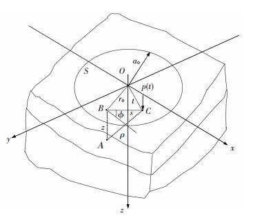
3 Analyses for a Coated Half-Space Indented by a Sphere When a sphere indents a coated half-space, the contact pressure p(t) is produced in a circle area S, shown in Fig. 2. And Hertzian pressure distribution is assumed as:
|
$
p\left( t \right) = \frac{{{p_0}}}{{{a_0}}}{\left( {a_0^2-{t^2}} \right)^{\frac{1}{2}}}
$
|
where a0 denotes the radius of the contact area and t is the distance from the coordinate origin which is the center of the indentation. By utilizing the fundamental solutions described in the previous section, the stresses at an arbitrary point A(x, y, z) inside the body and displacements of a point B(x, y) on the surface can be obtained through the superposition method.
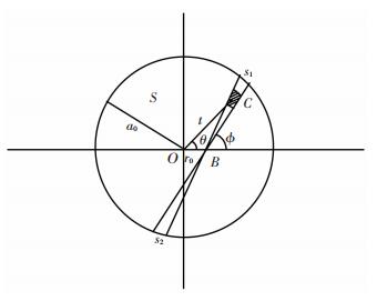
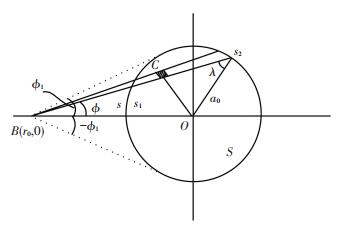
Firstly, a local polar coordinate system (s, ϕ) is set at an arbitrary point B(x, y) as the origin on the surface of the half-space. The pressure on the element area around point C is pdsdϕ which can be regarded as a concentrated force, as shown in Figs. 3 and 4. Hence, the displacements and stresses of B(x, y) on the surface and A(x, y, z) inside the body under pdsdϕ can be calculated using the fundamental solution given in the previous section. Where A(x, y, z) is a point just beneath B(x, y) with the same x and y coordinates. Obviously, the displacements and stresses at any point can be computed by integration.
In this paper, the normal displacement on the surface is discussed in detail since it is often mainly concerned and can be used to predict the contact radius.
Substituting the force Pz by psdsdϕ in the stress functions expressed as Eqs.(14)-(17):
|
$
\begin{array}{l}
{\varphi _i}\left( {{R_i}, {z_i}} \right) =-\frac{{ps{\rm{d}}s{\rm{d}}\phi }}{{2{\rm{\pi }}}}\left\{ {{H_{i, 0}}\log \left( {{R_i}-{z_i}} \right) + \frac{{{H_{i, 1}}}}{{{R_i}}} + } \right.\\
\;\;\;\;\;\;\;\;\;\;\;\;\;\;\;\;\;\left. {\sum\limits_{k = 1}^{N-1} {{H_{i, k + 1}}\frac{{{\partial ^k}}}{{\partial {z^k}}}\frac{1}{{{R_i}}}} } \right\}
\end{array}
$
|
(18) |
|
$
{\psi _i}\left( {{R_i}, {z_i}} \right) =-\frac{{ps{\rm{d}}s{\rm{d}}\phi }}{{2{\rm{\pi }}}}\left\{ {\frac{{{G_{i, 1}}}}{{{R_i}}} + \sum\limits_{k = 1}^N {{G_{i, k + 1}}\frac{{{\partial ^k}}}{{\partial {z^k}}}\frac{1}{{{R_i}}}} } \right\}
$
|
(19) |
|
$
\begin{array}{l}
{\beta _i}\left( {{\rho _i}, {\zeta _i}} \right) =-\frac{{ps{\rm{d}}s{\rm{d}}\phi }}{{2{\rm{\pi }}}}\left\{ {{M_{i, 0}}\log \left( {{\rho _i}, {\zeta _i}} \right) + \frac{{{M_{i, 1}}}}{{{\rho _i}}} + } \right.\\
\;\;\;\;\;\;\;\;\;\;\;\;\;\;\;\;\;\;\left. {\sum\limits_{k = 1}^{N + 1} {{M_{i, k + 1}}\frac{{{\partial ^k}}}{{\partial {z^k}}}\frac{1}{{{\rho _i}}}} } \right\}
\end{array}
$
|
(20) |
|
$
{\eta _i}\left( {{\rho _i}, {\zeta _i}} \right) =-\frac{{ps{\rm{d}}s{\rm{d}}\phi }}{{2{\rm{\pi }}}}\left\{ {\frac{{{N_{i, 1}}}}{{{\rho _i}}} + \sum\limits_{k = 1}^{N + 1} {{N_{i, k + 1}}\frac{{{\partial ^k}}}{{\partial {z^k}}}\frac{1}{{{\rho _i}}}} } \right\}
$
|
(21) |
Noting that on the surface z1=z=0, the normal displacement on the surface for any point B(x, y) can be written as:
|
$
2{\mu _1}\bar w = \frac{{\partial {\mathit{\Phi }_1}}}{{\partial z}}-\left( {3-4{\nu_1}} \right){\mathit{\Psi }_{\rm{Ⅰ}}}
$
|
Under the force psdsdϕ on an area element, one can obtain:
|
$
\begin{array}{l}
\frac{{\partial {\mathit{\Phi }_1}}}{{\partial z}} = \frac{\partial }{{\partial z}}\left[{\sum\limits_{i = 1}^\infty {{\varphi _i}\left( {r, {z_i}} \right)} + \sum\limits_{i = 1}^\infty {{\beta _i}\left( {r, {\zeta _i}} \right)} } \right] = \\
\;\;\;\;\;\;\;\;\;\; - \frac{{ps{\rm{d}}s{\rm{d}}\phi }}{{2{\rm{\pi }}}}\sum\limits_{i = 1}^\infty {\left[{-\frac{{{H_{i, 0}}}}{{{R_i}}}-\frac{{{H_{i, 0}}}}{{R_i^3}} + } \right.} \\
\;\;\;\;\;\;\;\;\;\;\frac{\partial }{{\partial z}}\left( {\sum\limits_{k = 1}^{N-1} {{H_{i, k + 1}}\frac{{{\partial ^k}}}{{\partial {z^k}}}\frac{1}{{{R _i}}}} } \right) + \\
\;\;\;\;\;\;\;\;\;\;\left. {\frac{{{M_{i, 0}}}}{{{\rho _i}}} - \frac{{{M_{i, 1}}}}{{\rho _i^3}} + \frac{\partial }{{\partial z}}\left( {\sum\limits_{k = 1}^{N + 1} {{M_{i, k + 1}}\frac{{{\partial ^k}}}{{\partial {z^k}}}\frac{1}{{{\rho _i}}}} } \right)} \right]
\end{array}
$
|
(22) |
|
$
\begin{array}{l}
{\mathit{\Psi }_{\rm{Ⅰ}}} = \sum\limits_{i = 1}^\infty {{\psi _i}\left( {r, {z_i}} \right)} + \sum\limits_{i = 1}^\infty {{\eta _i}\left( {r, {\zeta _i}} \right)} = \\
\;\;\;\;\;\;\;\;- \frac{{ps{\rm{d}}s{\rm{d}}\phi }}{{2{\rm{\pi }}}}\sum\limits_{i = 1}^\infty {\left[{\frac{{{G_{i, 0}}}}{{{R_i}}} + \sum\limits_{k = 1}^{N-1} {{G_{i, k + 1}}\frac{{{\partial ^k}}}{{\partial {z^k}}}\frac{1}{{{R_i}}} + } } \right.} \\
\;\;\;\;\;\;\;\;\left. {\frac{{{N_{i, 1}}}}{{{\rho _i}}} + \sum\limits_{k = 1}^{N + 1} {{N_{i, k + 1}}\frac{{{\partial ^k}}}{{\partial {z^k}}}\frac{1}{{{\rho _i}}}} } \right]
\end{array}
$
|
(23) |
As the same time, in the stress functions r should be substituted by s, we have:
|
$
{R_i} = \sqrt {{s^2} + z_i^2}, {z_i} = 2\left( {i-1} \right)h
$
|
(24) |
|
$
{\rho _i} = \sqrt {{s^2} + \zeta _i^2}, {\zeta _i} =-2ih
$
|
(25) |
Using Eqs.(24)-(25) and noting that z1=z=0 on the surface, Eqs.(22) and (23) can be rewritten as:
|
$
\begin{array}{l}
\frac{{\partial {\mathit{\Phi }_1}}}{{\partial z}} =- \frac{{ps{\rm{d}}s{\rm{d}}\phi }}{{2{\rm{\pi }}}}\sum\limits_{i = 1}^\infty {\left[{\frac{{{{\tilde H}_{i, 0}}}}{{{R_i}}} + \sum\limits_{k = 1}^{N-1} {{{\tilde H}_{i, k}}\frac{1}{{R_i^{2k + 1}}} + \frac{{{{\tilde M}_{i, 0}}}}{{{\rho _i}}} + } } \right.} \\
\;\;\;\;\;\;\;\;\;\;\left. {\sum\limits_{k = 1}^{N + 2} {{{\tilde M}_{i, k + 1}}\frac{1}{{\rho _i^{2k + 1}}}} } \right]\\
{\mathit{\Psi }_{\rm{Ⅰ}}} = - \frac{{ps{\rm{d}}s{\rm{d}}\phi }}{{2{\rm{\pi }}}}\sum\limits_{i = 1}^\infty {\left[{\frac{{{{\tilde G}_{i, 0}}}}{{{R_i}}} + \sum\limits_{k = 1}^N {{{\tilde G}_{i, k + 1}}\frac{1}{{R_i^{2k + 1}}} + } } \right.} \\
\;\;\;\;\;\left. {\frac{{{{\tilde N}_{i, 1}}}}{{{\rho _i}}} + \sum\limits_{k = 1}^{N + 1} {{{\tilde N}_{i, k + 1}}\frac{1}{{\rho _i^{2k + 1}}}} } \right]
\end{array}
$
|
where, the coefficients ${\tilde H_{i, 0}},\;{\tilde H_{i, k}},\;{\tilde M_{i, 0}},\;{\tilde M_{i, k + 1}}{\tilde G_{i, 0}},\;{\tilde G_{i, k + 1}},\;{\tilde N_{i, 1}},\;{\tilde N_{i, k + 1}} $ are constants. The normal displacement of B(x, y) on the surface under Hertzian pressure has the form as follows:
|
$
\bar w\left( {{r_0}} \right) =-\frac{1}{{4{\rm{\pi }}{\mu _1}}}\iint\limits_S {p\left( {s, \phi } \right)f\left( s \right)s{\text{d}}s{\text{d}}\phi }
$
|
(26) |
where
|
$
\begin{array}{l}
f\left( s \right) = \frac{{{{\tilde H}_{1, 0}} + \left( {3- 4{\nu_1}} \right){{\tilde G}_{1, 0}}}}{{{R_1}}} + \\
\;\;\;\;\;\;\;\;\;\;\;\sum\limits_{i = 2}^\infty {\left[{\frac{{{{\tilde H}_{i, 0}}}}{{{R_i}}} + \sum\limits_{k = 1}^N {{{\tilde H}_{i, k}}\frac{1}{{R_i^{2k + 1}}} + \frac{{\left( {3-4{\nu_1}} \right){{\tilde G}_{1, 0}}}}{{{R_1}}} + } } \right.} \\
\;\;\;\;\;\;\;\;\;\;\;\left. {\left( {3-4{\nu_1}} \right)\sum\limits_{k = 1}^N {{{\tilde G}_{i, k + 1}}\frac{1}{{R_i^{2k + 1}}}} } \right] + \\
\;\;\;\;\;\;\;\;\;\;\;\sum\limits_{i = 1}^\infty {\left[{\frac{{{{\tilde M}_{i, 0}}}}{{{R_i}}} + \sum\limits_{k = 1}^{N + 2} {{{\tilde M}_{i, k + 1}}\frac{1}{{\rho _i^{2k + 1}}} + } } \right.} \\
\;\;\;\;\;\;\;\;\;\;\;\left. {\frac{{\left( {3-4{\nu_1}} \right){{\tilde N}_{i, 1}}}}{{{\rho _i}}} + \left( {3-4{\nu_1}} \right)\sum\limits_{k = 1}^{N + 1} {{{\tilde N}_{i, k + 1}}\frac{1}{{\rho _i^{2k + 1}}}} } \right]
\end{array}
$
|
(27) |
Or
|
$
\begin{array}{l}
f\left( s \right) = \frac{{{n_0}}}{{{R_1}}} + \sum\limits_{i = 2}^\infty {\left[{\frac{{{n_{i, 0}}}}{{{R_i}}} + \sum\limits_{k = 1}^N {{n_{i, k}}\frac{1}{{R_i^{2k + 1}}}} } \right]} + \\
\;\;\;\;\;\;\;\;\;\;\;\;\sum\limits_{i = 1}^\infty {\left[{\frac{{{m_{i, 0}}}}{{{\rho _i}}} + \sum\limits_{k = 1}^{N + 2} {{m_{i, k + 1}}\frac{1}{{\rho _i^{2k + 1}}}} } \right]}
\end{array}
$
|
(28) |
where, n0, ni, 0, mi, 0, ni, k, mi, k+1 can be computed by the coefficients in Eq.(27). Apparently, f(s) is a function of variable s. Noting that, for a specified point the coordinates are constants in the integral of Eq.(26). As the result the displacement of B(x, y) obtained by integration varies with the distance r0 from the origin (as shown in Figs. 3-5). Where, Fig. 3 shows that point B(x, y) is inside the contact area, one can obtain:
|
$
{t^2} = r_0^2 + {s^2} + 2{r_0}s\cos \phi
$
|
therefore
|
$
p\left( {s, \phi } \right) = \frac{{{p_0}}}{{{a_0}}}{\left( {\alpha _0^2-2{\beta _0}s-{s^2}} \right)^{\frac{1}{2}}}
$
|
where $\alpha _0^2 = a_0^2-{r_0}^2$ and β0=r0cos ϕ. When B(x, y) is an interior point of contact area Eq.(26) can be rewritten as:
|
$
\bar w =-\frac{{{p_0}}}{{4{\rm{\pi }}{\mu _1}{a_0}}}\int_0^{2{\rm{\pi }}} {{\rm{d}}\phi } \int_0^{{s_1}} {{{\left( {\alpha _0^2-2{\beta _0}s-{s^2}} \right)}^{\frac{1}{2}}}f\left( s \right)s{\rm{d}}s}
$
|
(29) |
where s1 is the positive root of "$r_0^2 + {s^2} + 2{r_0}s\cos \phi = 0$".
For an external point B(x, y), as shown in Fig. 4, the limits of the integration in Eq.(29) are from "-ϕ1" to "ϕ1" and from "s1" to "s2". Where
|
$
{s_{1, 2}} =-2{r_0}\cos \phi \pm \sqrt {r_0^2{{\cos }^2}\phi-\left( {a_0^2-r_0^2} \right)}
$
|
And
|
$
p\left( {s, \phi } \right) = \frac{{{p_0}}}{{{a_0}}}\left( {\left( {a_0^2-r_0^2} \right) + 2{r_0}\cos \phi-{s^2}} \right)
$
|
Substituting Eqs.(24)-(25) into Eq.(28), one can obtain:
|
$
\begin{array}{l}
f\left( s \right) = \frac{{{n_0}}}{s} + \sum\limits_{i = 2}^\infty {\left[{\frac{{{n_{i, 0}}}}{{\sqrt {{s^2} + 4{{\left( {i- 1} \right)}^2}{h^2}} }} + } \right.} \\
\;\;\;\;\;\;\;\;\;\;\;\;\left. {\sum\limits_{i = 1}^N {{n_{i, k}}\frac{1}{{{{\left[{{s^2} + 4{{\left( {i-1} \right)}^2}{h^2}} \right]}^{\frac{{2k + 1}}{2}}}}}} } \right] + \\
\;\;\;\;\;\;\;\;\;\;\;\;\sum\limits_{i = 1}^\infty {\left[{\frac{{{m_{i, 0}}}}{{\sqrt {{s^2} + 4{i^2}{h^2}} }} + \sum\limits_{k = 1}^{N + 2} {{m_{i, k + 1}}\frac{1}{{{{\left( {{s^2} + 4{i^2}{h^2}} \right)}^{\frac{{2k + 1}}{2}}}}}} } \right]}
\end{array}
$
|
(30) |
Through the above procedures, it can be seen that the first coefficient in the function f(s) expressed by Eq.(30) is derived from φ1 and ψ1 defined by Eqs.(12)-(13), which are the stress functions for a concentrated force normal to the surface for homogeneous half-space. Therefore, one can obtain:
|
$
{n_0} =-2\left( {1-{\nu_1}} \right)
$
|
When substituting Eq.(30) into Eq.(29), the integration of the first term is:
|
$
\begin{array}{l}
{{\bar w}_1}\left( {{r_0}} \right) = \frac{{1-\nu_1^2}}{{{\rm{\pi }}{E_1}}}\frac{{{p_0}}}{{{a_0}}}\int_0^{2{\rm{\pi }}} {\frac{{\rm{\pi }}}{4}\left( {a_0^2-r_0^2 + r_0^2{{\cos }^2}\phi } \right){\rm{d}}\phi } = \\
\;\;\;\;\;\;\;\;\;\;\;\;\;\frac{{1-\nu_1^2}}{{{E_1}}}\frac{{{\rm{\pi }}{p_0}}}{{4{a_0}}}\left( {2a_0^2 - r_0^2} \right), {r_0} \le {a_0}
\end{array}
$
|
This is the surface normal displacement of a homogeneous half space under Herzian loading. Other terms are Elliptical integral.
Using the above solutions, the contact radius a0 and penetration depth δ can be approximately predicted. According to the theory of Hertz[20] we can write:
|
$
w\left( {r = 0, z = 0} \right) + w'\left( {r = 0, z = 0} \right) = \delta
$
|
(31) |
|
$
w\left( {r = {a_0}, z = 0} \right) + w'\left( {r = {a_0}, z = 0} \right) = \delta-\frac{{a_0^2}}{{2R}}
$
|
(32) |
The normal displacement w(r=0, z=0) is computed using Eq.(29). w′ is the displacement for the indenter which can be calculated using the solution for the homogeneous body:
|
$
w' = \frac{{3HP{\rm{\pi }}}}{{8a_0^3}}\left( {2a_0^2-{r^2}} \right), H = \frac{{1-{\nu^2}}}{E}
$
|
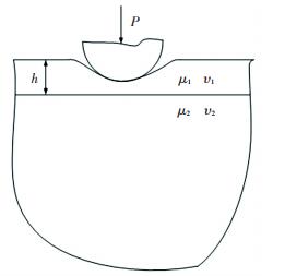
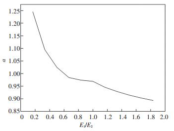
Here E, ν are the elastic modulus and Poisson's ratio of the indenter. Using Eqs.(31) and (32), the contact radius can be predicted under Hertz loading considering the effect of the substrate. The indentation model is shown as Fig. 5 and the computing results as Fig. 6. Where, the load P is taken 10 kN, the radius of the sphere 20 mm, the elastic modulus of the substrate 300 GPa.
From Fig. 6 it can be seen that the contact radius decreases with the increase of the elastic modulus of the film.
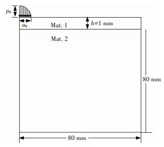
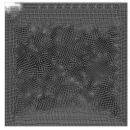
4 Numerical Results and Discussion Comparisons of the theoretical solutions to the results of FEM for an axi-symmetric problem subjected Hertz loading on the surface are performed using ANSYS to show the validity of the above theories. The axisymmetric model must be created such that the global Y-axis is the axis of symmetry, and the entire model should appear on the right side of the Y-axis, as shown in Fig. 7. Since the actual theoretical problem is about half-infinite space with very thin upper layer, the dimensions of the substrate should be very large. The elements divisions are shown in Fig. 8, using 8-node quadrilateral elements with the axisymmetric option activated.
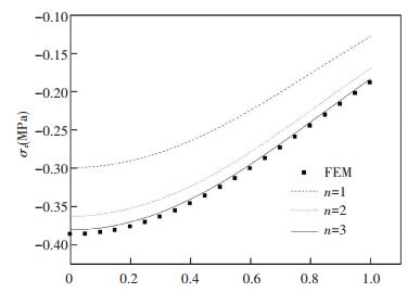
The elastic constants of the materials are shown in Table 1. In the FEM model we take a0=1 mm and p0=1 N in Hertz loading (see the Hertzian pressure expression in Section 3). In the process of FEM calculation the axisymmetric boundary conditions are applied along the Y-axis and the bottom line is fixed. The problem is simply elastostatic and can be solved with one load step. The results of surface normal displacement and the normal stress σz along the interface are shown in Figs. 9 and 10, respectively.
表 1

Table 1 Material constants
| Material |
Young's modulus E(GPa) |
Poisson's ratio ν |
| Ⅰ |
546 |
0.3 |
| Ⅱ |
206 |
0.3 |
|
Table 1 Material constants
|
In the legends of Fig. 10, n means the order of the image point. Where, in Fig. 9 the dashed dot line, i.e., n=0, represents the displacement corresponding to the solution for homogenous half-space under Hertz loading. By comparing with the FEM results, it can be found that the stress and displacement increments decrease rapidly as the order of the image points increasing. And the results of superposition with 3 image points have good accuracy for the selected materials combination. These imply that the theoretical solutions converge very quickly. In Fig. 9, the dashed line is the result corresponding to the first order image point, the dot line denotes the result of the superposition of the first two order image points, and the solid line represents the superposition of the three order image points. It can be seen that the first term corresponding to the solution for homogenous half-space with the film's properties provides the main contribution to the displacement, however, the effects of the substrate should be considered since the increments of the first and second order image points cannot be neglected. From the figures, it is obviously that the theoretical result is approaching the numerical one with more image points. And just taking into account a few image points the result has a good accuracy. It can be concluded that if more image points are added, more accurate results can be obtained.
From the stress functions one can find that the materials parameters are included explicitly and the thickness of the upper thin layer implicitly, i.e., the displacements and stresses vary with the combinations of the materials and the thickness of the upper layer. Therefore, the solutions obtained in this work can be used in the indentation test and the optimization design of coated systems in engineering. With the fixed thickness of the layer, the appropriate combination of bi-materials can be selected based on the calculations of the stresses at the interface. On the other hand, when the combined materials are selected, the thickness of the upper layer can be optimized. However, there are a lot of work to do using the solutions in coated materials design and indentation tests. For example, a great deal of experiments and computations of stresses need to be performed. Hence, the thorough and detailed studies of the applications of the theoretical results would be presented in another paper.
5 Conclusions In this paper, elastic analyses of thin-film coated half-space indented by a sphere are performed. Elastic solutions are given in the form of infinite series. By comparison with the FEM results, it can be concluded that the exact solutions have a good convergence rate. Therefore, for practical applications only a few image points need to be used to ensure the accuracy.
From the analyses, it is shown that the first term in the solutions corresponding to the solution for homogenous half-space with the film's properties provides the main contribution to the displacement, however, the effects of the substrate cannot be ignored.
The solutions presented in this paper can be used in the indentation tests and to solve contact problems which are the basis of the tribological issue.

 0)
0)
 0)
0)
 0)
0)
 0)
0)
 0)
0)
 0)
0)
 0)
0)
 0)
0)
 0)
0)
 0)
0)
 0)
0)
 0)
0)
 0)
0)
 0)
0)
 0)
0)
 0)
0)
 0)
0)
 0)
0)
 0)
0)
 0)
0)
 2017, Vol. 24


