2. Key Laboratory of Functional Materials and Applications of Fujian Province, Xiamen 361024, China;
3. College of Civil Engineering, Huaqiao University, Xiamen 361021, China;
4. School of Material Science and Engineering, South China University of Technology, Guangzhou 510640, China
Chromate passivation has been widely used as an anti-corrosion technique because it provides outstanding corrosion resistance with excellent self-healing and it is economical and simple to apply[1-3]. However, Cr6+ is highly toxic, and thus there is an incentive to find some suitable alternatives. A number of chromium-free passivation films have been investigated, such as phosphate[4], molybdate[5], rare earth salt[6], silicate[7], silane[8] and resin[9]. Unfortunately, the corrosion resistance is apparently poorer than that of chromate film, and most lack self-healing property. Recently, some self-healing polymeric or inorganic coatings for corrosion protection of metal have been studied[10-16].
Phosphating is an important chemical conversion process used for corrosion protection and as a painting primer for metal. However, the corrosion resistance of coating is limited because the pores between phosphate crystals cannot be eliminated completely. In previous work[17], a continuous and complete coating was produced on hot-dip galvanised (HDG) steel by phosphating and molybdate post-sealing, and it was found that there was a synergistic effect of two single films. Moreover, the corrosion was not found after spraying in NSS chamber for 5 days, whereas the relative corroded area was about 100% and 70%, respectively, of the single-molybdate-passivated sample and the single-phosphated sample. The corrosion resistance of the composite coating is outstanding, but, if the application is to be widened, it is important to determine whether it has good self-healing capability.
Electrochemical testing and microscopic analysis are two common techniques to assess the self-healing of the protective coating on metal[18-19]. An increase in low-frequency impedance during corrosion indicates a self-repair of the damage in coating. Yabuki et al.[20] scratched the protective coating on aluminium and then immersed in 5% NaCl solution at 40 ℃. The results showed that the polarisation resistance increased continuously and the scratches contained diethyl o-phthalate, coming from the coating. Aramaki[21] coated zinc with Ce2O3 and Na3PO4 and then corroded the scratched samples in 0.5 molL-1 NaCl solution. The XPS and electron probe micro analysis results suggested that the corrosion of zinc was inhibited by the formation of Zn3(PO4)2, Zn(OH)2 and ZnO in the scratches.
In this paper, the phosphated/molybdate post-sealed samples were first scratched and then corroded by NSS for different duration, and the morphology of the scratches was studied. The composition of the composite coating was analysed, and the electrochemical corrosion behavior was investigated.
2 Experimental 2.1 Preparation of the CoatingHDG steel was self-made in laboratory[17]. The phosphating and molybdate post-sealing parameters are shown in Table 1. The solution was prepared from analytic reagents and de-ionised water.
| Table 1 Technical parameters of phosphating and molybdate post-sealing |
The designations of the HDG samples prepared with various technologies are present in Table 2.
| Table 2 Designations for HDG samples prepared with various technologies |
2.2 XPS Analysis
To elucidate the self-healing mechanism of the composite coating, the chemical composition of the coating was investigated. The coating is so thin that the X-ray diffraction signal will be overwhelmed by that of the matrix. In this work, XPS with an Axis UltraDLD instrument and an Mg Kα X-ray source was used to analyze the elemental composition and valence state of the composite coating.
2.3 SEM and EDS Analysis of the ScratchesA scratch with 40-μm-width was made on the surface of the coated sample until the zinc layer was exposed. Then the sample was corroded in NSS chamber (YWX/Q150) for various time. And the morphology and composition of the scratches before and after corrosion was analyzed with SEM (Philips XL-30-FEG) and EDS (EDAX DX-4).
2.4 EIS MeasurementEIS measurement was performed under CHI604B electrochemical workstation. The corrosion system contained three electrodes, i.e. working electrode, reference electrode (served by saturated calomel electrode, SCE) and auxiliary electrode (served by platinum electrode). The corrosion medium was a non-deaerated 5% NaCl solution. EIS measurement was conducted at a steady open circuit potential. The frequency was between 100 kHz and 0.01 Hz. The potential amplitude was 5 mV.
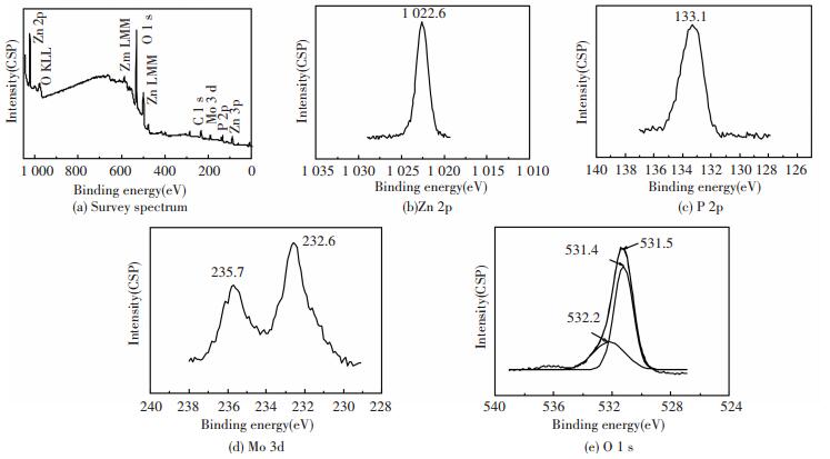
3 Results and Discussion 3.1 Composition of the CoatingFig. 1 displays the XPS spectra of the composite coating. Mo, P, O, Zn and C are observed. Here, the C element may be due to the environmental pollution for it was disappeared after slightly sputtering with Ar+. The atomic fraction of Mo, P, O and Zn is 3.4%, 21.8%, 61.9% and 12.9%, respectively.
|
Figure 1 XPS spectra of the composite coating |
The binding energy of 1022.6 eV in the Zn 2p3/2 spectrum in Fig. 1(b) is consistent with the value of 1022.7 eV for Zn2+ in Zn3(PO4)2. The broad peak of P 2p3/2 at 133.1 eV in Fig. 1(c) corresponds to P5+ in Zn3(PO4)2 at 133.4 eV[22].
The broad spectrum of Mo 3d can be divided into two peaks at 232.6 eV and 235.7 eV (Fig. 1(d)). These two peaks can be assigned to Mo 3d5/2 (at 232.6 eV) and Mo 3d3/2 (at 235.8 eV) in Mo2O3, respectively[23]. They are also close to the corresponding peaks in MoO42- at 232.2 eV and 235.4 eV.
In Fig. 1(e), the broad spectrum of O 1s can be separated into two peaks at 532.2 eV and 531.4 eV. The peak with higher binding energy can be assigned to H2O. And the other peak is corresponding to that of Zn3(PO4)2 (at 531.5 eV), Mo2O3 (at 531.6 eV) and MoO42- (at 531.2 eV).
The results indicate the presence of Zn3(PO4)2·4H2O, Mo2O3 and MoO42- (possibly in the form of Na2MoO4 and/or ZnMoO4) on the surface of the composite coating.
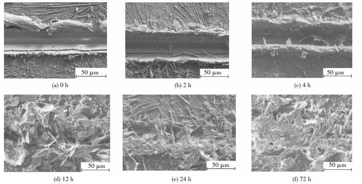
3.2 Microstructure and Composition on ScratchesFig. 2 shows SEM images (at low magnify-cation) of the scratches on P+Mo after NSS spraying for various duration. The scratch without corrosion (Fig. 2(a)) is bright and clean and, according to the EDS analysis, reveals the naked zinc layer. At the edge of the scratch, the composite coating can be seen to be extruded and flaked.
|
Figure 2 SEM micrographs (at low magnification) of scratches on P+Mo after NSS spraying for various duration |
After 2 h of corrosion (Fig. 2(b)), a few flakes are formed in the scratch. Increasing the NSS spraying time (Fig. 2(c)), these flakes increase in number and size. After 12 h of corrosion (Fig. 2(d)), needles and flakes are present throughout the scratch. After 24 h (Fig. 2(e)), the corrosion products have formed a compact mass, with flakes continuing to grow and with some bridging the scratch (a distance of about 40 μm). At 72 h (Fig. 2(f)), an extremely compact mass of the corrosion products fills the whole scratch and appears to extend above the original coating surface.
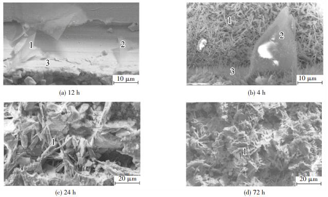
Fig. 3 presents the higher-magnification SEM images of the corrosion products on scratches, and Table 3 lists the composition of different micro-sites indicated in this figure.
|
Figure 3 SEM micrographs (at high magnification) of scratches on P+Mo with various NSS spraying duration |
| Table 3 Chemical constituents of micro areas correspondedto Fig. 3 |
With NSS spraying for 2 h (Fig. 3(a)), there are a few flake-like crystals in the range of 20-50 μm. The composition of the scratch as a whole includes oxygen, phosphorus, molybdenum and chloride (Table 3). The phosphorus and oxygen contents of the flake-like crystals are higher than those of the smooth surface, but the molybdenum content is lower and the chloride content much lower. It is possible that there is an amorphous molybdate thin film on the smooth surface[24], and the flake-like crystals may be zinc phosphate, similar to those reported in Ref.[4]. According to the results of XPS analysis, Zn3(PO4)2·4H2O, Mo2O3 and Na2MoO4 (or ZnMoO4) are present in the composite coating. Due to the insolubility is relative, these compounds, especially Na2MoO4, can dissolve in corrosive media[25], leading to the production of PO43-, Zn2+ and, particularly, MoO42-. These ions also transfer to the scratch. Moreover, in corrosive media, micro-corrosion cells are formed on the naked zinc layer. Zinc dissolves at the micro-anode, producing Zn2+. Reduction of oxygen takes place at the micro-cathode, generating OH-. When the concentration product of zinc phosphate, zinc molybdate and zinc hydroxide is met due to the generation of these ions, the protective compounds are thus formed and cover the scratch or the defects in the coating. The corrosion of the naked zinc layer will thus be effectively hindered. This is similar to the self-healing process of chromate passivation film due to the presence of hexavalent chromium. Thus, the phosphated/molybdate post-sealed composite coating also has a self-healing property.
After corrosion for 4 h (Fig. 3(b)), there are clear changes in the microstructure of the scratch. The dense and tiny acicular-like crystals completely cover the bottom surface of the scratch, the edge of the scratch is overgrown with slender whisker-like crystals and the original flake-like crystals continue growing and thickening. It appears that the corrosion products formed after 2 h of corrosion act as the nucleation sites for further corrosion, leading to a significant growth in corrosion products, which also become more compact with a finer structure. After 4 h of corrosion, the amount of chloride and molybdenum in the scratch as a whole is respectively increased and decreased compared with the situation at 2 h (Table 3). Oxygen and phosphorus on the bottom surface is decreased, but in the flake-like crystals and at the edges they are clearly enhanced. It can be considered that zinc phosphate is continuously deposited on the initial flake-like crystals, in a manner similar to that reported for the growth pattern of phosphate coating[4]. Most of the dissolved PO43- is re-deposited at the edges of the scratch, at a shorter diffusion distance, with a small proportion diffusing a longer distance to the bottom surface of the scratch and reforming the original compounds.
After corrosion for 24 h (Fig. 3(c)), there is a clear increase in the amount of the corrosion products, with slender whisker-like crystals reaching from edge to edge. The EDS results show a clear decrease in phosphorus and molybdenum but a large increase in chloride (Table 3). As corrosion proceeds, active chloride ions speed up the dissolution of the composite coating. Some of the dissolved PO43- and MoO42- precipitate as insoluble compounds, but a great part maybe diffuse into the corrosive media, resulting in a gradual decrease in the self-healing capacity of the coating.
With NSS spraying for 72 h (Fig. 3(d)), there are a great number of new-formed fine corrosion products which overlap on the surface of the original larger crystals, but many pores are present. The amount of phosphorus and molybdenum in the crystals continues to decrease, whereas oxygen and chloride increase greatly. Moreover, the zinc content decreases (Table 3). The corrosion products on the scratch continue thickening.
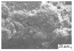
It should be noted that although the chloride content rises with the increasing of the corrosion time, the corrosion products on the exposed zinc layer of the scratches are outstandingly distinct from the "white rust"-namely, basic zinc chloride, which are flocculent and loose and thus without protection -on the traditional zinc layer, as shown in Fig. 4. In other words, the products on scratches are fine and dense, and are greatly changed by the initial formation of zinc phosphate crystals and amorphous molybdate thin film, repairing the defects of the coating and inhibiting the formation and expansion of matrix corrosion.
|
Figure 4 'White rust' on the traditional zinc layer |
3.3 Electrochemical Corrosion Behavior
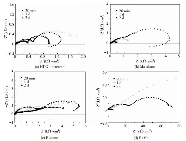
Fig. 5 shows the Nyquist diagrams of HDG-untreated, Mo-alone, P-alone and P+Mo immersed in 5%NaCl solution for different duration. For HDG-untreated (Fig. 5(a)), with the increasing corrosion time, a low-frequency inductive loop first appears as zinc is dissolved, then disappears as zinc corrosion is inhibited by the formation of the protective corrosion products and then reappears as it is dissolved again[26-27], while the impedance first increases and then decreases. In NaCl solution, Zn2+ and OH- are generated during the corrosion of zinc layer. When the concentrations of these two ions satisfy the concentration product of Zn(OH)2, 3 × 10-17, Zn(OH)2 is deposited, and then gradually is dehydrated to ZnO. Both Zn(OH)2 and ZnO form a compact and protective layer. With continuing corrosion, the electrochemical reactions decrease owing to the coverage of these corrosion products on zinc, resulting in a decreased production of Zn2+ and OH-, and thus the formation of Zn(OH)2 slows down. Meanwhile, the active chloride ions and OH- are competitively adsorbed on zinc, and a loose Zn2+-Cl--OH- complex is formed. The active chloride ions are the corrosion catalysts, causing the formation and development of the corrosion pits[21, 27].
|
Figure 5 EIS diagrams for different samples immersed in 5% NaCl solution for different time |
As shown in Figs. 5(b)-5(d), with the increasing of the corrosion time, the impedance of Mo-alone and P-alone decreases continuously, while that of P+Mo first increases and then decreases, although it remains at a higher value than that of Mo-alone and P-alone. The low-frequency impedance ZLF, which is characterised by the double-layer capacitance and the charge-transfer resistance, reflects the difficulty of the electrochemical reaction at the corrosion electrode[28]. The greater the value of ZLF is, the more difficult are the electrochemical reactions, and the more effective is the inhibition of zinc corrosion.
Fig. 6 presents the changes of ZLF of P+Mo with corrosion time for different phosphating time. It can be seen that, in general, the longer the phosphating time is, the higher is the value of ZLF. For all values of the phosphating time, as the corrosion time increases, ZLF first increases and then decreases. However, ZLF of P+Mo after immersion for 6 days in 5% NaCl solution are still in the region of 10 kΩ·cm2, higher than that of P-alone and Mo-alone without corrosion, due to the compact and fine corrosion products.

|
Figure 6 Changes of ZLF of P+Mo with corrosion time (immersion in 5% NaCl solution) for different phosphating time (indicated, in seconds, by the number next to 'P') |
4 Conclusions
1) The phosphated/molybdate post-sealed composite coating is composed of Zn3(PO4)2·4H2O, Mo2O3 and MoO42- (Na2MoO4 and/or ZnMoO4).
2) The composite coating displays good resistance to corrosion. The impedance of the coated samples in 5% NaCl solution first increases and then decreases with corrosion time, but remains at 10 kΩ·cm2 after corrosion for 6 days, much higher than that of the single-treated samples without corrosion.
3) The composite coating exhibits good self-healing. During the initial stage of corrosion, scratches are covered with flake-like crystals of zinc phosphate and amorphous thin films of molybdate, with negligible amounts of chloride. With a longer duration of corrosion, the products cover the whole scratch completely and the chloride content increases. However, these corrosion products, in contrast to those initially produced, form very compact masses composed of fine needle-like crystals. They are therefore able to effectively inhibit the corrosion of zinc layer.
| [1] |
Tencer M. Electrical conductivity of chromate conversion coating on electrodeposited zinc.
Applied Surface Science, 2006, 252(23): 8229-8234.
DOI:10.1016/j.apsusc.2005.10.039 ( 0) 0)
|
| [2] |
Magalhaes A A O, Tribollet B, Mattos O R, et al. Chromate conversion coatings formation on zinc studied by electrochemical and electrohydrodynamical impedances.
Journal of the Electrochemical Society, 2003, 150(1): 16-25.
DOI:10.1149/1.1528196 ( 0) 0)
|
| [3] |
Akihiro Y. Particle-induced damage and subsequent healing of materials: erosion, corrosion and self-healing coatings.
Advanced Powder Technology, 2011, 22(3): 303-310.
DOI:10.1016/j.apt.2010.10.016 ( 0) 0)
|
| [4] |
Lin B L, Kong G, Lu J T, et al. Growth and corrosion resistance of zinc phosphate conversion coatings on hot dip galvanized steel.
The Chinese Journal of Nonferrous Metals, 2007, 17(5): 800-806.
( 0) 0)
|
| [5] |
Liu D L, Yang Z G, Wang Z Q, et al. Synthesis and evaluation of corrosion resistance of molybdate-based conversion coatings on electroplated zinc.
Surface and Coatings Technology, 2010, 205(7): 2328-2334.
DOI:10.1016/j.surfcoat.2010.09.018 ( 0) 0)
|
| [6] |
Ramezanzadeh B, Vakili H, Amini R. Improved performance of cerium conversion coatings on steel with zinc phosphate post-treatment.
Journal of Industrial and Engineering Chemistry, 2015, 30(10): 225-233.
DOI:10.1016/j.jiec.2015.05.026 ( 0) 0)
|
| [7] |
Zhan J, Chen G M, Liu X F, et al. Corrosion mechanism of HVOF silicate glass coating in 5% NaCl solution.
Journal of Harbin Institute of Technology (New Series), 2010, 17(2): 264-268.
( 0) 0)
|
| [8] |
Chen S G, Cai Y C, Zhuang C, et al. Electrochemical behavior and corrosion protection performance of bis-[triethoxysilylpropyl] tetrasulfide silane films modified with TiO2 sol on 304 stainless steel.
Applied Surface Science, 2015, 331(15): 315-326.
DOI:10.1016/j.apsusc.2015.01.008 ( 0) 0)
|
| [9] |
Wang Z, Liu L M. Corrosion resistant performances of Al-rich epoxy resin based paint on arc-sprayed Al coating.
Materials and Corrosion, 2010, 61(2): 152-156.
DOI:10.1002/maco.200905242 ( 0) 0)
|
| [10] |
Zheludkevich M L, Tedim J, Freire C S R, et al. Self-healing protective coatings with "green" chitosan based pre-layer reservoir of corrosion inhibitor.
Journal of Materials Chemistry, 2011, 21(13): 4805-4812.
DOI:10.1039/C1JM10304K ( 0) 0)
|
| [11] |
Samadzadeh M, Hatami B S, Peikari M, et al. A review on self-healing coatings based on micro/nanocapsules.
Progress in Organic Coatings, 2010, 68(3): 159-164.
DOI:10.1016/j.porgcoat.2010.01.006 ( 0) 0)
|
| [12] |
Zhao Y, Zhang W, Liao L P, et al. Self-healing coatings containing microcapsule.
Applied Surface Science, 2012, 258(6): 1915-1918.
DOI:10.1016/j.apsusc.2011.06.154 ( 0) 0)
|
| [13] |
Aramaki K. Preparation of chromate-free, self-healing polymer films containing sodium silicate on zinc pretreated in a cerium(Ⅲ) nitrate solution for preventing zinc corrosion at scratches in 0.5 M NaCl.
Corrosion Science, 2002, 44(6): 1375-1389.
DOI:10.1016/S0010-938X(01)00138-X ( 0) 0)
|
| [14] |
Zhang R Y, Cai S, Xu G H, et al. Crack self-healing of phytic acid conversion coating on AZ31 magnesium alloy by heat treatment and the corrosion resistance.
Applied Surface Science, 2014, 313(15): 896-904.
DOI:10.1016/j.apsusc.2014.06.104 ( 0) 0)
|
| [15] |
Hamdy A S, Doench I, Mohwald H. Intelligent self-healing corrosion resistant vanadia coating for AA2024.
Thin Solid Films, 2011, 520(5): 1668-1678.
DOI:10.1016/j.tsf.2011.05.080 ( 0) 0)
|
| [16] |
Yuan M R, Lu J T, Kong G, et al. Self healing ability of silicate conversion coatings on hot dip galvanized steels.
Surface and Coatings Technology, 2011, 205(19): 4507-4513.
DOI:10.1016/j.surfcoat.2011.03.088 ( 0) 0)
|
| [17] |
Lin B L, Lu J T, Kong G. Effect of molybdate post-sealing on the corrosion resistance of zinc phosphate coatings on hot-dip galvanized steel.
Corrosion Science, 2008, 50(4): 962-967.
DOI:10.1016/j.corsci.2007.12.002 ( 0) 0)
|
| [18] |
Zheludkevich M L, Yasakau K A, Bastos A C, et al. On the application of electrochemical impedance spectroscopy to study the self-healing properties of protective coatings.
Electrochemistry Communications, 2007, 9(10): 2622-2628.
DOI:10.1016/j.elecom.2007.08.012 ( 0) 0)
|
| [19] |
Montemor M F, Snihirova D V, Taryba M G, et al. Evaluation of self-healing ability in protective coatings modified with combinations of layered double hydroxides and cerium molybdate nanocontainers filled with corrosion inhibitors.
Electrochimica Acta, 2012, 60: 31-40.
DOI:10.1016/j.electacta.2011.10.078 ( 0) 0)
|
| [20] |
Yabuki A, Okuno H. Self-healing corrosion protective capability of polymer coatings for aluminum.
Journal of the Japan Institute of Light Metals, 2011, 61(12): 724-728.
DOI:10.2464/jilm.61.724 ( 0) 0)
|
| [21] |
Aramaki K. XPS and EPMA studies on self-healing mechanism of a protective film composed of hydrated cerium(Ⅲ) oxide and sodium phosphate on zinc.
Corrosion Science, 2003, 45(1): 199-210.
DOI:10.1016/S0010-938X(02)00086-0 ( 0) 0)
|
| [22] |
Gresch R, Müller-Warmuth W, Dutz H. X-ray photoelectron spectroscopy of sodium phosphate glasses.
Journal of Non-Crystalline Solids, 1979, 34(1): 127-136.
DOI:10.1016/0022-3093(79)90012-7 ( 0) 0)
|
| [23] |
Clayton C R, Lu Y C. A bipolar model of the passivity of stainless steel-Ⅲ: the mechanism of MoO42- formation and incorporation.
Corrosion Science, 1989, 29(7): 881-884.
DOI:10.1016/0010-938X(89)90059-0 ( 0) 0)
|
| [24] |
Wu H J, Lu J T. Corrosion resistance ofsilane films on hot-dip galvanized steel by molybdate post-sealing.
Acta Physico-Chimica Sinica, 2009, 25(9): 1743-1748.
DOI:10.3866/PKU.WHXB20090821.(inChinese) ( 0) 0)
|
| [25] |
Lin B L, Lu J T, Li Y C. Growth mechanism of composite coatings obtained by phosphating and cerium nitrate post-sealing on galvanized steel.
The Chinese Journal Nonferrous Metals, 2014, 24(8): 1008-1013.
( 0) 0)
|
| [26] |
Cachet C, Ganne F, Joiret S, et al. EIS investigation of zinc dissolution in aerated sulphate medium. Part Ⅱ: zinc coatings.
Electrochimica Acta, 2002, 47(21): 3409-3422.
DOI:10.1016/S0013-4686(02)00277-3 ( 0) 0)
|
| [27] |
Jegannathan S, Sankara N T S N, Ravichandran K, et al. Performance of zinc phosphate coatings obtained by cathodic electrochemical treatment in accelerated corrosion tests.
Electrochimica Acta, 2005, 51(2): 247-256.
DOI:10.1016/j.electacta.2005.04.020 ( 0) 0)
|
| [28] |
Bonnel K, Pen C L, Pebere N. EIS characterization of protective coatings on aluminum alloys.
Electrochimica Acta, 1999, 44(24): 4259-4267.
DOI:10.1016/S0013-4686(99)00141-3 ( 0) 0)
|
 2017, Vol. 24


