2. Resource Department, Southwest China Research Institute of Electronic Equipment, Chengdu 610000, China
Aero-elastic panel flutter is one kind of dynamic instability behavior owing to coupling actions of aerodynamic loading, inertia and elastic force. When panel flutter happens, amplitudes of vibration are increased dramatically. This behavior may result in fatigue failure of high speed vehicles. The flutter behaviors were first observed on V-2 rockets, after that a number of researchers have investigated panel flutter utilizing different aerodynamic and structural theories. Dowell[1-2] presented surveys of early researches. Mei et al.[3] reviewed experimental as well as analytical methods about panel flutter applied in resent years. Birman and Librescu[4] analyzed aero-elastic instability of shear deformable panels under supersonic airflow. Kouchakzadeh[5] studied the aero-elasticity problem of laminated composite plates, where the classic plate theory was adopted to simulate the structure dynamic, and the aerodynamic loading was simulated by linear piston theory. Numerical results in Kouchakzadeh[5] indicated that laminated ply angles played an important part in the flutter boundary. Zhao et al.[6] studied the flutter behaviors of stiffened laminated composite panels under nonlinear aerodynamic loading. Results obtained in Zhao et al.[6] indicated that the stiffener position had an important effect on flutter boundary of the panel. Xie et al.[7] analyzed panel flutter behavior using the proper orthogonal decomposition (POD) method. Zhao et al.[8] investigated the aero-elastic behaviors of laminated composite panels under actions of acoustic, aerodynamic and thermal loadings. Zhang et al.[9] analyzed the aerothermoelastic phenomenon of a reinforced functionally graded composite panel under supersonic flow.
In resent years, numerous researches utilizing smart materials have been carried out about active and passive control of panel flutter. Birman[10] presented a review about industry applications of SMA devices. Through heating, the pre-strained SMA can generate large recovery stresses. Thus, embedding SMA wires in the layers of composite structures can alter the system stiffness. Park et al.[11] employed FEM to analyze the influences of SMA on buckling and flutter boundary of the smart plate. The aerodynamic loading is simulated by linear piston theory and simulation of SMA thermo-mechanical behavior is according to experimental data. Ostachowicz et al.[12] utilized FEM to analyze the thermal buckling and flutter behaviors of a composite plate with SMA fibers. In accordance to first-order shear deformation plate theory, Barzegari et al.[13] analyzed influences of embedded SMA wires on the flutter boundary of a smart cantilever wing, where the aerodynamic loading was estimated by linear piston theory. Samadpour et al.[14] investigated the aero-elastic behaviors of SMA fiber reinforced composite beams. Asadi et al.[15] utilized SMA fibers to suppress nonlinear thermal buckling behaviors of a composite panel.
In this paper, to predict the dynamical behavior of the laminated composite panel embedded with SMA wires, the classical plate theory and Von-Karman nonlinear strain-displacement relation are employed to derive the nonlinear governing differential equations of motion. In the process of modeling, the aerodynamic loadings are simulated by third order piston theory, while the thermo-mechanical behavior of SMA wires is estimated according to one-dimensional Brinson SMA model. The system discrete dynamic model is established by the Galerkin method. The numerical results are given to show the influences of SMA wires on natural frequency, flutter boundary and amplitude of LCO of a laminated composite panel.
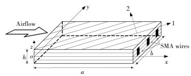
2 Theoretical FormulationA composite panel embedded with SMA wires in Cartesian co-ordinate system with thickness h, length a and width b is displayed in Fig. 1. The panel is composed of 4 layers under supersonic airflow along the positive x direction. The SMA wires are embedded in the second and third layer symmetrically.
|
Figure 1 The sketch of smart laminated panel |
2.1 Classical Plate Theory
Based on the classical plate theory, the displacements u(x, y, z, t), v(x, y, z, t) and z(x, y, z, t) in the x, y and z directions may be written as:
| $ \left\{ \begin{array}{l} u\left( {x,y,z,t} \right) = {u_0}\left( {x,y,z,t} \right) - z\frac{{\partial {w_0}\left( {x,y,t} \right)}}{{\partial x}}\\ v\left( {x,y,z,t} \right) = {v_0}\left( {x,y,t} \right) - z\frac{{\partial {w_0}\left( {x,y,t} \right)}}{{\partial y}}\\ w\left( {x,y,z,t} \right) = {w_0}\left( {x,y,t} \right) \end{array} \right. $ | (1) |
where subscript '0' denotes mid-plane displacement. The nonlinear strain-displacement relations, according to the Von-Karman's assumption, are:
| $ \left\{ \begin{array}{l} {\varepsilon _x}\\ {\varepsilon _y}\\ {\gamma _{xy}} \end{array} \right\} = \left\{ \begin{array}{l} \frac{{\partial {u_0}}}{{\partial x}} + \frac{1}{2}{\left( {\frac{{\partial {w_0}}}{{\partial x}}} \right)^2} - z\frac{{{\partial ^2}{w_0}}}{{\partial {x^2}}}\\ \frac{{\partial {v_0}}}{{\partial y}} + \frac{1}{2}{\left( {\frac{{\partial {w_0}}}{{\partial y}}} \right)^2} - z\frac{{{\partial ^2}{w_0}}}{{\partial {y^2}}}\\ \frac{{\partial {u_0}}}{{\partial y}} + \frac{{\partial {v_0}}}{{\partial x}} + \frac{{\partial {w_0}}}{{\partial x}}\frac{{\partial {w_0}}}{{\partial y}} - 2z\frac{{{\partial ^2}{w_0}}}{{\partial x\partial y}} \end{array} \right\} $ | (2) |
When transformed to the laminated coordinate, the constitutive law for the nth conventional layer is
| $ {\left\{ \begin{array}{l} {\sigma _x}\\ {\sigma _y}\\ {\tau _{xy}} \end{array} \right\}_{\left( n \right)}} = \mathit{\boldsymbol{T}}_{\left( n \right)}^{ - 1}{\mathit{\boldsymbol{Q}}_{m\left( n \right)}}\mathit{\boldsymbol{T}}_{\left( n \right)}^{ - {\rm{T}}}\left\{ \begin{array}{l} {\varepsilon _x}\\ {\varepsilon _y}\\ {\gamma _{xy}} \end{array} \right\} = {{\mathit{\boldsymbol{\bar Q}}}_{m\left( n \right)}}\left\{ \begin{array}{l} {\varepsilon _x}\\ {\varepsilon _y}\\ {\gamma _{xy}} \end{array} \right\} $ | (3) |
where subscript 'm' and 'n' denotes the composite matrix and layer number, respectively. The stiffness matrix Qm and transform matrix T(n) are[16-17]
| $ {\mathit{\boldsymbol{Q}}_m} = \left[ {\begin{array}{*{20}{c}} {{Q_{11m}}}&{{Q_{12m}}}&0\\ {{Q_{12m}}}&{{Q_{22m}}}&0\\ 0&0&{{Q_{66m}}} \end{array}} \right] $ | (4) |
and
| $ \begin{array}{l} {\mathit{\boldsymbol{T}}_{\left( n \right)}} = \\ \;\;\;\left[ {\begin{array}{*{20}{c}} {{{\cos }^2}{\theta _{\left( n \right)}}}&{{{\sin }^2}{\theta _{\left( n \right)}}}&{2\sin {\theta _{\left( n \right)}}\cos {\theta _{\left( n \right)}}}\\ {{{\sin }^2}{\theta _{\left( n \right)}}}&{{{\cos }^2}{\theta _{\left( n \right)}}}&{ - 2\sin {\theta _{\left( n \right)}}\cos {\theta _{\left( n \right)}}}\\ { - \sin {\theta _{\left( n \right)}}\cos {\theta _{\left( n \right)}}}&{2\sin {\theta _{\left( n \right)}}\cos {\theta _{\left( n \right)}}}&{{{\cos }^2}{\theta _{\left( n \right)}} - {{\sin }^2}{\theta _{\left( n \right)}}} \end{array}} \right] \end{array} $ | (5) |
respectively. Here, Q11m, Q22m, Q12m and Q66m are the stiffness coefficents which are defined as Q11m=E1m/(1-υ12mυ21m), Q22m=E2m/(1-υ12mυ21m), Q12m=υ12mE2m/(1-υ12mυ21m), Q66m=G12m, in which E1m, E2m and G12m are the Young modulus and shear modulus, and υ12m and υ21m are Poisson ratios.
And for the kth smart layer, the constitutive law becomes[18]:
| $ {\left\{ \sigma \right\}_{\left( k \right)}} = {{\mathit{\boldsymbol{\bar Q}}}_k}\left\{ \varepsilon \right\} + {\mathit{\boldsymbol{T}}^{ - 1}}{\left\{ {{\sigma _r}} \right\}_{\left( k \right)}}{V_{s\left( k \right)}} $ | (6) |
where subscripts 's' stands for the SMA wires and 'k' is layer number. {σr} is recovery stress vectors introduced by SMA wires. Vs denotes SMA wires volume fractions.
The elastic properties of the smart laminated panel are given as:
| $ \left\{ \begin{array}{l} {E_1} = {E_s}{V_s} + {E_{1m}}{V_m}\\ {\upsilon _{12}} = {\upsilon _s}{V_s} + {\upsilon _{12m}}{V_m}\\ {E_2} = \frac{{{E_s}{E_{2m}}}}{{{E_s}{V_m} + {E_{2m}}{V_s}}}\\ {G_{12}} = \frac{{{G_s}{G_{12m}}}}{{{G_s}{V_m} + {G_{12m}}{V_s}}}\\ \rho = {\rho _s}{V_s} + {\rho _m}{V_m}\\ {V_s} + {V_m} = 1 \end{array} \right. $ | (7) |
where, ρ, υ, G and E denote density, Poisson ratio, shear modulus and Young modulus, respectively. Vm stands for volume fraction of composite matrix.
2.2 Description of the Stress Model of SMA WiresAccording to the one-dimensional SMA model proposed by Brinson[19] and assuming all SMA wires are fully constrained, one can obtain the SMA recovery stress as:
| $ {\sigma _{\rm{r}}} = \left\{ \begin{array}{l} {\sigma _0} + \mathit{\Theta }\left( {T - {T_0}} \right),\;\;\;\;\;\;\;0 \le T \le A_s^\sigma \\ {\sigma _1} + \left[ {{E_s}\left( \xi \right) - {E_s}\left( {{\xi _0}} \right)} \right]{\varepsilon _0} + \mathit{\Omega }\left( \xi \right){\xi _s} - \\ \;\;\;\;\;\mathit{\Omega }\left( {{\xi _0}} \right){\xi _{s0}} + \mathit{\Theta }\left( {T - A_s^\sigma } \right),ZA_s^\sigma \le T \le A_f^\sigma \\ {\sigma _2} + \mathit{\Theta }\left( {T - A_f^\sigma } \right),\;\;\;\;\;\;\;T \ge A_f^\sigma \end{array} \right. $ | (8) |
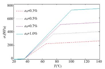
The parameters in Eq.(8) can be obtained from the literature[19]. Fig. 2 shows the computed SMA recovery stress versus various temperatures with four prestrain levels. It is seen that in the phase transformation state, large recovery stresses can be generated. Moreover, for higher pre-strain, raising SMA wires temperature will generate larger recovery stresses.
|
Figure 2 SMA recovery stress |
2.3 Modeling of Aerodynamic Pressure
Aerodynamic pressure Δp, estimated by the third order piston theory in present research, is given as:
| $ \begin{array}{l} \Delta p = \frac{{2q}}{M}\left[ {\frac{{{{\dot w}_0}}}{{{v_\infty }}} + \frac{{\partial {w_0}}}{{\partial x}} + \frac{{\left( {\gamma + 1} \right)M}}{4}{{\left( {\frac{{{{\dot w}_0}}}{{{v_\infty }}} + \frac{{\partial {w_0}}}{{\partial x}}} \right)}^2} + } \right.\\ \;\;\;\;\;\;\;\;\;\left. {\frac{{\left( {\gamma + 1} \right){M^2}}}{{12}}{{\left( {\frac{{{{\dot w}_0}}}{{{v_\infty }}} + \frac{{\partial {w_0}}}{{\partial x}}} \right)}^3}} \right] \end{array} $ | (9) |
where M and γ stand for the Mach number and ratio of specific heats, q=ρav∞2 denotes the dynamic pressure, v∞ and ρa stand for the air stream velocity and density.
2.4 Equations of MotionBased on Hamilton's principle, the dynamic governing equations for the smart laminated panel may be established as follows:
| $ \int_{{t_0}}^{{t_1}} {\left( {\delta T + \delta W - \delta U} \right){\rm{d}}t} = 0 $ | (10) |
where δT and δU stand for virtual kinetic and virtual strains energy, δW is virtual work done by aerodynamic loading:
| $ \left\{ \begin{array}{l} \delta T = \int_0^b {\int_0^a {\int_{ - \frac{h}{2}}^{\frac{h}{2}} {\rho \left( {\dot u\delta \dot u + \dot v\delta \dot v + \dot w\delta \dot w} \right){\rm{d}}z{\rm{d}}x{\rm{d}}y} } } \\ \delta U = \int_0^b {\int_0^a {\int_{ - \frac{h}{2}}^{\frac{h}{2}} {\left( {{\sigma _x}\delta {\varepsilon _x} + {\sigma _y}\delta {\varepsilon _y} + {\tau _{xy}}\delta {\gamma _{xy}}} \right){\rm{d}}z{\rm{d}}x{\rm{d}}y} } } \\ \delta W = - \int_0^b {\int_0^a {\Delta p\delta w\left( {x,y,0.5h} \right){\rm{d}}x{\rm{d}}y} } \end{array} \right. $ | (11) |
Substituting Eqs.(1)-(7) in Eq.(11) and setting the virtual displacements coefficients to be zero, one have:
| $ \left\{ \begin{array}{l} \frac{{\partial {N_{xx}}}}{{\partial x}} + \frac{{\partial {N_{xy}}}}{{\partial y}} = {I_0}{{\ddot u}_0}\\ \frac{{\partial {N_{yy}}}}{{\partial y}} + \frac{{\partial {N_{xy}}}}{{\partial x}} = {I_0}{{\ddot v}_0}\\ \left( {\frac{{\partial {N_{xx}}}}{{\partial x}} + \frac{{\partial {N_{xy}}}}{{\partial y}}} \right)\frac{{\partial {w_0}}}{{\partial x}} + \left( {\frac{{\partial {N_{yy}}}}{{\partial y}} + \frac{{\partial {N_{xy}}}}{{\partial x}}} \right)\frac{{\partial {w_0}}}{{\partial y}} + \\ \;\;\;{N_{xx}}\frac{{{\partial ^2}{w_0}}}{{\partial {x^2}}} + {N_{yy}}\frac{{{\partial ^2}{w_0}}}{{\partial {y^2}}} + 2{N_{xy}}\frac{{{\partial ^2}{w_0}}}{{\partial x\partial y}} + \frac{{{\partial ^2}{M_{xx}}}}{{\partial {x^2}}} + \\ \;\;\;\frac{{{\partial ^2}{M_{yy}}}}{{\partial {x^2}}} + 2\frac{{{\partial ^2}{M_{xy}}}}{{\partial x\partial y}} - \Delta p = {I_0}{{\ddot w}_0} - {I_2}\left( {\frac{{{\partial ^2}{{\ddot w}_0}}}{{\partial {x^2}}} + \frac{{{\partial ^2}{{\ddot w}_0}}}{{\partial {y^2}}}} \right) \end{array} \right. $ | (12) |
where the force resultants operator and the mass moments of inertias, Nkl, Mkl(k, l=x, y), Ii (i=0, 2) can be given as:
| $ \left\{ {\begin{array}{*{20}{c}} {\left[ \begin{array}{l} {N_{xx}}\\ {N_{yy}}\\ {N_{xy}} \end{array} \right] = \int_{ - \frac{h}{2}}^{\frac{h}{2}} {\left[ \begin{array}{l} {\sigma _x}\\ {\sigma _y}\\ {\tau _{xy}} \end{array} \right]{\rm{d}}z} }\\ {\left[ \begin{array}{l} {M_{xx}}\\ {M_{yy}}\\ {M_{xy}} \end{array} \right] = \int_{ - \frac{h}{2}}^{\frac{h}{2}} {\left[ \begin{array}{l} {\sigma _x}\\ {\sigma _y}\\ {\tau _{xy}} \end{array} \right]z{\rm{d}}z} }\\ {\left( {{I_0},{I_2}} \right) = \int_{ - \frac{h}{2}}^{\frac{h}{2}} {\rho \left( {1,{z^2}} \right){\rm{d}}z} } \end{array}} \right. $ |
For a simply supported panel, the displacements satisfying the boundary conditions can be given as:
| $\left\{ {\begin{array}{*{20}{l}} {{u_0}\left( {x,y,t} \right) = \sum\limits_{i = 1}^l {\sum\limits_{j = 1}^m {{a_{ij}}\left( t \right)\sin \left( {\frac{{i{\rm{ \mathsf{ π} }}x}}{a}} \right)\sin \left( {\frac{{j{\rm{ \mathsf{ π} }}y}}{b}} \right)} } }\\ {{v_0}\left( {x,y,t} \right) = \sum\limits_{i = 1}^l {\sum\limits_{j = 1}^m {{b_{ij}}\left( t \right)\sin \left( {\frac{{i{\rm{ \mathsf{ π} }}x}}{a}} \right)\sin \left( {\frac{{j{\rm{ \mathsf{ π} }}y}}{b}} \right)} } }\\ {{w_0}\left( {x,y,t} \right) = \sum\limits_{i = 1}^l {\sum\limits_{j = 1}^m {{c_{ij}}\left( t \right)\sin \left( {\frac{{i{\rm{ \mathsf{ π} }}x}}{a}} \right)\sin \left( {\frac{{j{\rm{ \mathsf{ π} }}y}}{b}} \right)} } } \end{array}} \right. $ | (13) |
Dowell's[20] research shows that one span wise mode and four stream wise modes are required to get accurate results. Thus, in this study l=4, m=1.
Substituting Eq.(13) in Eq.(12) and integrating over the panel area, the panel discrete dynamic model can be derived:
| $ \left\{ \begin{array}{l} {{\ddot a}_i} = \frac{4}{{ab{I_0}}}\int_0^a {\int_0^b {\left( {\frac{{\partial {N_{xx}}}}{{\partial x}} + \frac{{\partial {N_{xy}}}}{{\partial y}}} \right){\mathit{\Phi }_i}\left( {x,y} \right){\rm{d}}x{\rm{d}}y} } \\ {{\ddot b}_i} = \frac{4}{{ab{I_0}}}\int_0^a {\int_0^b {\left( {\frac{{\partial {N_{yy}}}}{{\partial y}} + \frac{{\partial {N_{xy}}}}{{\partial x}}} \right){\mathit{\Phi }_i}\left( {x,y} \right){\rm{d}}x{\rm{d}}y} } \\ {{\ddot c}_i} = \frac{{4ab}}{{{a^2}{b^2}{I_0} + \left( {{i^2}{b^2} + {a^2}} \right){{\rm{\pi }}^2}{I_2}}}\int_0^a {\int_0^b {\left( {\left( {\frac{{\partial {N_{xx}}}}{{\partial x}} + \frac{{\partial {N_{xy}}}}{{\partial y}}} \right)\frac{{\partial {w_0}}}{{\partial x}} + } \right.} } \\ \;\;\;\;\;\;\left( {\frac{{\partial {N_{yy}}}}{{\partial y}} + \frac{{\partial {N_{xy}}}}{{\partial x}}} \right)\frac{{\partial {w_0}}}{{\partial y}} + \frac{{{\partial ^2}{M_{xx}}}}{{\partial {x^2}}} + \frac{{{\partial ^2}{M_{yy}}}}{{\partial {x^2}}} + 2\frac{{{\partial ^2}{M_{xy}}}}{{\partial x\partial y}}\\ \left. {{N_{xx}}\frac{{{\partial ^2}{w_0}}}{{\partial {x^2}}} + {N_{yy}}\frac{{{\partial ^2}{w_0}}}{{\partial {y^2}}} + 2{N_{xy}}\frac{{{\partial ^2}{w_0}}}{{\partial x\partial y}} - \Delta p} \right){\mathit{\Phi }_i}\left( {x,y} \right){\rm{d}}x{\rm{d}}y \end{array} \right. $ | (14) |
Let
| $ \mathit{\boldsymbol{y = }}{\left\{ {{a_1},{{\dot a}_1}, \cdots ,{a_4},{{\dot a}_4},{b_1},{{\dot b}_1}, \cdots ,{b_4},{{\dot b}_4},{c_1},{{\dot c}_1}, \cdots ,{c_4},{{\dot c}_4}} \right\}^{\rm{T}}} $ |
then, Eq.(14) may be written in the following expression:
| $ \dot y = \mathit{\boldsymbol{A}}y + \mathit{\boldsymbol{g}}\left( y \right) $ | (15) |
where, A is the Jacobian matrix and g(y) denotes the nonlinear vectors.
3 Results and DiscussionPanel flutter will happen as dynamic pressure λ is higher than critical flutter dynamic pressure λcr. The general solution of Eq.(15) is
| $ y\left( t \right) = {y_0}{e^{{\varphi _j}t}},{\varphi _j} = {\alpha _j} \pm {\rm{i}}{\beta _j} $ |
where φj and y0 denote the eigenvalues of the matrix A and initial value of the state y. The natural frequencies can be expressed as:
| $ {\omega _j} = \sqrt {\beta _j^2} $ |
When the real part of any eigenvalue turns into positive, the panel flutter will occur. Thus, via observing the variation of maximum real part of eigenvalues μ, λcr may be figured out. μ is given by:
μ=max[Re(φj)]=max(αj)
In this study, the smart laminated panel with length 0.3 m, width 0.12 m and thickness 0.001 m is taken for simulation. The maximum amplitude for the transverse vibration is plotted at the point (0.75a, 0.5b). The material parameters of the smart laminated panel are given as:
Graphite/epoxy properties: E1m=138 GPa, E2m=9.7 GPa, G12m=5.5 GPa, ρm=1 580kg/m3, υm=0.3.
SMA wires properties: EA=67 GPa, EM=26.3 GPa, Ms=18.4 ℃, Mf=9 ℃, As=34.5 ℃, Af=49 ℃, CM=8 MPa/℃, CA=13.8 MPa/℃, Θ=0.55, εl=0.067, σ0=0, T0=20 ℃, ρs=6 450 kg/m3, ξT0=0, υs=0.33.
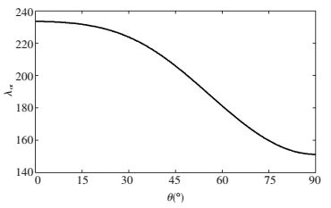
Effects of SMA layer orientation on flutter boundary for different angle of SMA wires are investigated first. The lay-up schedule is assumed to be [90/θSMA/θSMA/90]. SMA wires have temperature 50 ℃, pre-strain 0.5% and volume fraction 1%, respectively. Fig. 3 displays the panel flutter boundary versus the angle of SMA wires. It is shown from Fig. 3 that changing the angle of SMA layer from 0° to 90° reduces the panel flutter boundary. Moreover, embedding SMA wires in the zero angle is the best way to improve the flutter boundary.
|
Figure 3 Flutter boundary versus SMA layer orientation |
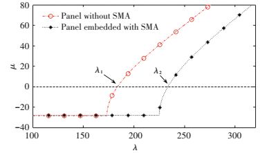
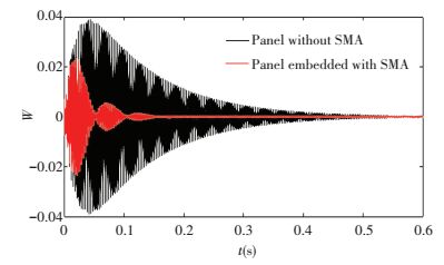
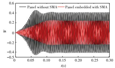
Stability margins for the smart/conventional laminated panel are shown in Fig. 4. SMA wires have temperature 50 ℃, pre-strain 0.5% and volume fractions 1%. The λcr of the conventional laminated panel is 183.83 as displayed in Fig. 4. The λcr is increased from λ1=183.83 to λ2=233.65 after the recovery stresses are generated. Figs. 5-7 present the time history for λ=178.49 < λ1, λ1 < λ=209.98 < λ2 and λ=251.98>λ2 respectively. As depicted in Fig. 5, before the critical flutter dynamic pressure for λ < λ1, transverse vibration reduces with time increasing. Also, the vibration amplitude of the smart panel converges quickly compared to the conventional panel. Fig. 6 depicts that the panel embedded with SMA wires becomes convergence when the panel without SMA wires has LCOs at λ=209.98 in the region λ1 < λ < λ2. Fig. 7 depicts that the amplitude of LCO of the smart laminated panel is smaller than the conventional panel at λ=251.98.
|
Figure 4 Comparison of flutter boundary for panel embedded with/ without SMA wires |
|
Figure 5 Time history for λ=178.49 |

|
Figure 6 Time history for λ=209.98 |
|
Figure 7 Time history for λ=251.98 |
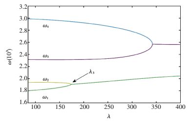
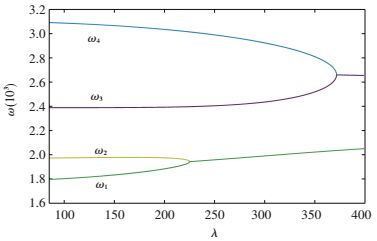
The curves of frequencies ω versus λ for the smart/conventional laminated panel are shown in Figs. 8 and 9 respectively. It can be found in Fig. 8 that as increasing the dynamic pressure the first 2-order natural frequency overlap to each other. The dynamic pressure λ3=173.43, at which ω1 and ω2 begin to overlap, is smaller than the dynamic pressure λ1=183.83, when μ intersects the real axis. That is because at the beginning of flutter, aerodynamic damping would consume part of the energy generated by aerodynamic pressure. Thus the panel flutter will not happen immediately at the time the first and the second frequencies equal to each other.
|
Figure 8 Frequencies of panel without SMA wires |
|
Figure 9 Frequencies of panel embedded with SMA wires |
For the variety of the natural frequencies, the panel embedded with SMA wires has the same trend as the conventional panel; however, the natural frequencies are reinforced because of the recovery stresses introduced by SMA wires as shown from Fig. 9.
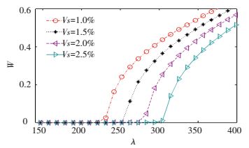
3.1 Effects of SMA Wires Volume Fraction on Aero-elastic BehaviorsThe recovery stresses introduced via heated SMA wires can improve panel stiffness. SMA wires have pre-strain of 0.5% and temperature of 50 ℃. It is observed as shown in Fig. 10 that the flutter boundary can be enhanced via raising the volume fraction. Fig. 11 demonstrates the amplitudes of LCO versus dynamic pressure under different SMA wires volume fraction. The numerical calculation reveals that the SMA wires can introduce large recovery stresses, which leads to a more stiffened panel for a wide range of dynamic pressure and thus a higher critical flutter dynamic pressure.

|
Figure 10 Effect of volume fraction on stability boundaries |
|
Figure 11 Amplitudes of LCO for different SMA wires volume fractions |
3.2 Effects of SMA Wires Temperature on Aero-elastic Behaviors
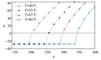
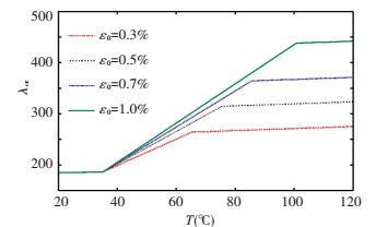
Effects of SMA wires temperature on the panel transverse vibration and flutter boundary are depicted in Figs. 12 and 13 with the parameters pre-strain 0.7% and volume fraction 1%. Raising the SMA wires temperature will increase SMA wires austenite fraction and the equal stiffness of the panel. Moreover, magnitude of the recovery stresses increases with raising the SMA wires temperature. For all these reasons, flutter boundary can be improved via increasing the SMA wires temperature as displayed in Fig. 12. Also it is demonstrated in Fig. 13 that the amplitude of limit cycle can be reduced by increasing the SMA wires temperature.
|
Figure 12 Effect of temperature on stability boundaries |

|
Figure 13 Amplitudes of LCO for different SMA wires temperatures |
3.3 Effects of SMA Wires Pre-strain on Aero-elastic Behaviors
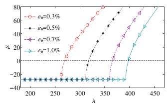
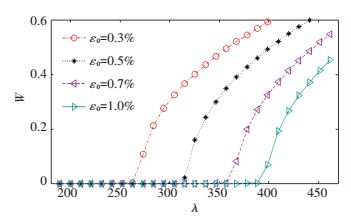
The effects of SMA wires pre-strain on aero-elastic behaviors of the panel are displayed in Figs. 14 and 15. SMA wires have volume fraction of 1% and temperature of 50 ℃. Raising SMA wires pre-strain results in an increase of recovery stresses. Thus, panel flutter boundary can be improved. It is clearly found from the Fig. 14 that increasing SMA wires pre-strain can improve the flutter boundary of the panel. Fig. 15 demonstrates the influences of SMA wires pre-strain on reducing the limit cycle oscillation amplitude. It is seen that, raising SMA wires pre-strain decreases the amplitude of limit cycle when the panel flutter happens. By increasing SMA wires pre-strain or temperature the critical boundary of the panel can be enhanced. Moreover, it is more efficient to improve the flutter boundary by increasing the pre-strain than increasing the temperature, see Fig. 16.
|
Figure 14 Effect of pre-strain on stability boundaries |
|
Figure 15 Amplitudes of LCO for different SMA wires pre-strains |
|
Figure 16 Critical dynamic flutter pressure versus SMA wires temperature with various pre-strain |
4 Conclusions
In this paper, the flutter behavior of a laminated composite panel embedded with SMA wires under nonlinear aerodynamic loadings has been investigated. The third order piston theory for aerodynamics, classic plate theory for structures as well as one-dimensional Brinson model for SMA wires have been used to derive the governing nonlinear dynamical equation of the smart laminated panel. Based on the Galerkin method, the system discrete dynamic model has been established. A composite panel with a set of typical material constants and geometrical parameters is taken as an example to illustrate the method proposed here. The Runge-Kutta method has been utilized to solve the system. The numerical results indicate that the flutter boundary can be enhanced via heating the SMA wires, raising SMA wires volume fraction or pre-strain. Therefore, the critical flutter dynamic pressure can be greatly increased and the amplitude of LCO can be significantly reduced for a given flutter dynamic pressure.
| [1] |
Dowell E H. Nonlinear oscillations of a fluttering plate. AIAA Journal, 1966, 4(7): 1267-1275. DOI:10.2514/3.3658 ( 0) 0)
|
| [2] |
Dowell E H. Panel flutter-A review of the aeroelastic stability of plates and shells. AIAA Journal, 1970, 8(3): 385-399. DOI:10.2514/3.5680 ( 0) 0)
|
| [3] |
Mei C, Abdel-Motagaly K, Chen R. Review of nonlinear panel flutter at supersonic and hypersonic speeds. Applied Mechanics Reviews, 1999, 52(10): 321-332. DOI:10.1115/1.3098919 ( 0) 0)
|
| [4] |
Birman V, Librescu L. Supersonic flutter of shear deformable laminated composite flat panels. Journal of Sound and Vibration, 1990, 139(2): 265-275. DOI:10.1016/0022-460X(90)90887-6 ( 0) 0)
|
| [5] |
Kouchakzadeh M A, Rasekh M, Haddadpour H. Panel flutter analysis of general laminated composite plates. Composite Structures, 2010, 92(12): 2906-2915. DOI:10.1016/j.compstruct.2010.05.001 ( 0) 0)
|
| [6] |
Zhao H, Cao D. A study on the aero-elastic flutter of stiffened laminated composite panel in the supersonic flow. Journal of Sound and Vibration, 2013, 332(19): 4668-4679. DOI:10.1016/j.jsv.2013.04.006 ( 0) 0)
|
| [7] |
Xie D, Xu M, Dai H, et al. Proper orthogonal decomposition method for analysis of nonlinear panel flutter with thermal effects in supersonic flow. Journal of Sound and Vibration, 2015, 337: 263-283. DOI:10.1016/j.jsv.2014.10.038 ( 0) 0)
|
| [8] |
Zhao H, Cao D. Supersonic flutter of laminated composite panel in coupled multi-fields. Aerospace Science and Technology, 2015, 47: 75-85. DOI:10.1016/j.ast.2015.09.019 ( 0) 0)
|
| [9] |
Zhang L W, Song Z G, Liew K M. Computation of aerothermoelastic properties and active flutter control of CNT reinforced functionally graded composite panels in supersonic airflow. Computer Methods in Applied Mechanics and Engineering, 2015, 300: 427-441. DOI:10.1016/j.cma.2015.11.029 ( 0) 0)
|
| [10] |
Birman V. Review of mechanics of shape memory alloy structures. Applied Mechanics Reviews, 1997, 50(11): 629-645. DOI:10.1115/1.3101674 ( 0) 0)
|
| [11] |
Park J S, Kim J H, Moon S H. Thermal post-buckling and flutter characteristics of composite plates embedded with shape memory alloy fibers. Composites Part B: Engineering, 2005, 36(8): 627-636. DOI:10.1016/j.compositesb.2004.11.007 ( 0) 0)
|
| [12] |
Ostachowicz W, Krawczuk M, ak A. Dynamics and buckling of a multilayer composite plate with embedded SMA wires. Composite Structures, 2000, 48(1): 163-167. DOI:10.1016/S0263-8223(99)00090-2 ( 0) 0)
|
| [13] |
Barzegari M M, Dardel M, Fathi A, et al. Aeroelastic characteristics of cantilever wing with embedded shape memory alloys. Acta Astronautica, 2012, 79: 189-202. DOI:10.1016/j.actaastro.2012.04.023 ( 0) 0)
|
| [14] |
Samadpour M, Asadi H, Wang Q. Nonlinear aero-thermal flutter postponement of supersonic laminated composite beams with shape memory alloys. European Journal of Mechanics-A/Solids, 2016, 57: 18-28. DOI:10.1016/j.euromechsol.2015.11.004 ( 0) 0)
|
| [15] |
Asadi H, Bodaghi M, Shakeri M, et al. An analytical approach for nonlinear vibration and thermal stability of shape memory alloy hybrid laminated composite beams. European Journal of Mechanics-A/Solids, 2013, 42: 454-468. DOI:10.1016/j.euromechsol.2013.07.011 ( 0) 0)
|
| [16] |
Birman V. Plate Structures (Solid Mechanics and Its Applications). Berlin:Springer, 2011. ( 0) 0)
|
| [17] |
Hu H T, Peng H W. Maximization of fundamental frequency of axially compressed laminated curved panels with cutouts. Composites Part B: Engineering, 2013, 47: 8-25. DOI:10.1016/j.compositesb.2012.10.047 ( 0) 0)
|
| [18] |
Hamed H, Tawfik M, Negm H M. Thermal buckling and nonlinear flutter behavior of shape memory alloy hybrid composite plates. Journal of Vibration and Control, 2011, 17(3): 321-333. DOI:10.1177/1077546309353368 ( 0) 0)
|
| [19] |
BrinsonL C. One-dimensional constitutive behavior of shape memory alloys: thermomechanical derivation with non-constant material functions and redefined martensite internal variable. Journal of Intelligent Material Systems and Structures, 1993, 4(2): 229-242. DOI:10.1177/1045389X9300400213 ( 0) 0)
|
| [20] |
Dowell E H. Nonlinear oscillations of a fluttering plate, Ⅱ. AIAA Journal, 1967, 5(10): 1856-1862. DOI:10.2514/3.4316 ( 0) 0)
|
 2017, Vol. 24


