Serval new type of mitigation devices have been developed in the past decades. Nonlinear energy sink (NES) has been studied to realize energy transferring from a linear oscillator (including multiple-degree-of-freedom system) to a strongly nonlinear oscillator in the irreversible way[1-3]. According to related research work, NES coupled in a mechanical system is able to absorb vibration efficiently in a wide frequency range[4-5]; the amplitude characteristic of the external forcing related to meanwhile[2, 6-7]. And, one study after another indicates that it is feasible to employ NES to reduce the vibration in some mechanical system, the spacecraft local vibration attenuation included as well[8-9].
Many researchers studied the energy transferring theory and mechanism for NES and some new conclusions were obtained. The energy dependence of the nonlinear normal modes (NNM) can be used to explain the targeted energy transfer (TET) in non-conservative or damped systems, all the damping forces ruled out in Refs.[6-7, 10]. On the basis of the approach of manifolds theory and phase trajectories, recent studies[10] also showed that system composed of primary oscillators and NES would represent the steady-state response, the weakly and strongly quasi-periodic response near the region of the main resonance under harmonic forcing. In Refs.[6-7, 11-12], the effect of NES on vibration suppression were discussed when a system took the sinusoidal excitation as its force input. In recent years, in spacecraft anti-vibration reduction fields, metal-rubber absorber has been widely used as an important shock absorber component, such as its application in instrument installed plate design[13-14]. Unfortunately, the design of metal-rubber absorbers is mainly depend on designers' experience and a large amount of ground tests[15-16]. There is very little research on the application of NES in spacecraft vibration attenuation, by far.
Motivated by the aforementioned observation, this paper will concentrate on the study of dynamical mechanism of metal-rubber vibration absorbers using the NES theory. We try to investigate dynamics mechanism of energy pumping for metal-rubber vibration absorber, by establishing an equivalent system consisted of a linear oscillator attached with a nonlinear oscillator under a sinusoidal force.
The paper is outlined as follows: we establish the mathematical models of the metal-rubber system in the first section. And based on the model, starting with the conditions of 1:1:1 resonance, we concentrate on the analysis of invariant manifold and phase portrait in the second section. Some results and their discussions are also given in this part. In order to verify analytical results derived above, some numerical work in the third section is given. Finally, the conclusions are given out on the basis of exposition in the last section. The treatments used in this paper include complex-variables averaging method, invariant manifold analysis and phase portrait analysis.
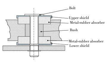
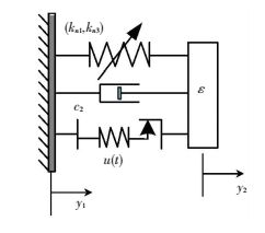
2 Depict of the Model and Analytic Method 2.1 Establishment of the Mechanical ModelThe profile of an instrument installed plate attached to a metal-rubber shock absorber for spacecraft is presented in Fig. 1. Fig. 2 shows the simplified model with an obvious hysteretic nonlinear structure for the shock absorber in Fig. 1. It is obvious that the relationship of elastic force and relative displacement is characteristic of the bilinear relation of stress-strain. And nonlinear of metal-rubber absorber makes the absorber different from NES with pure cubic stiffness in common research, such as NES in Refs.[2-3, 6].
|
Figure 1 Cutaway view of metal damping pad |
|
Figure 2 Model of metal rubber vibration absorber |
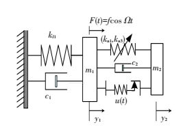
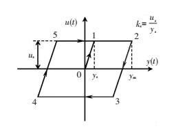
Based on this, we consider a mechanical model as shown in Fig. 3, in which a low damped linear primary oscillator with the mass m1 is taken to represent the main structure, and a bilinear hysteretic nonlinear attachment is introduced for the metal-rubber coupled to the main structure. Fig. 4 shows the bilinear hysteretic restoring force of the nonlinear attachment.
|
Figure 3 Primary oscillator attached to a NES absorber |
|
Figure 4 The bilinear hysteretic restoring force |
Dynamical motion of the whole bilinear hysteretic system can be described by a set of equations
| $ \left\{ \begin{array}{l} {{\ddot y}_1} + \varepsilon {\lambda _1}{{\dot y}_1} + {y_1} + \varepsilon {\lambda _1}\left( {{{\dot y}_1} - {{\dot y}_2}} \right) + \varepsilon {k_{n1}}\left( {{y_1} - {y_2}} \right) + \\ \;\;\;\;\;\;{k_{n3}}{\left( {{y_1} - {y_2}} \right)^3} - \varepsilon u\left( t \right) = \varepsilon A\cos t\\ \varepsilon {{\ddot y}_2} + \varepsilon {\lambda _2}\left( {{{\dot y}_2} - {{\dot y}_1}} \right) + \varepsilon {k_{n1}}\left( {{y_2} - {y_1}} \right) + {k_{n3}}\left( {{y_2} - } \right.\\ \;\;\;\;\;\;{\left. {{y_1}} \right)^3} + \varepsilon u\left( t \right) = 0 \end{array} \right. $ | (1) |
where y1 and y2 refer to the displacements of two oscillators, respectively; ελ1 and ελ2 are the damping coefficient of the linear and nonlinear oscillator; kn1 and kn3 represent the linear and the nonlinear stiffness; εA denotes the amplitude of the external excitation. To simplify the problems, the frequency normalization of external excitation is proposed. And, ε
The bilinear hysteretic relationship between elastic force and relative displacement can be expressed as the following incremental equations
| $ {\rm{d}}u\left( t \right) = 0.5 \cdot {k_s} \cdot \left[ {1 + {\mathop{\rm sgn}} \left( {{u_s} - \left| {u\left( t \right)} \right|} \right)} \right] \cdot {\rm{d}}y\left( t \right) $ | (2) |
where y=y2-y1 and ks=us/ys; ks, us and ys denote linear stiffness coefficient before hysteretic slip of vibration, the memory elastic force and the limited slip displacement. It is worth noting that there are non-differentiable points at u(t)=±us in Eq.(2). The derivatives do not exist at turning points 2, 3, 4, 5 and 1 in Fig. 3, but increments exist. Therefore, the derivative of du/dy equals to zero in interval t1~t2(t5~t2), except for the turning points.
Here, we assume damping of the primary oscillator is zero because we only pay attention to the NES, and the energy dependence of the undamped system which is obtained when all the damp forces are vanish[17-18]. Where ε
As shown in Fig. 4, the elastic force-displacement curve forms a single closed ring in stationary state except for an initial step. As we can see in the curve of bilinear hysteretic restoring force, the initial step from zero to ys corresponds to a hysteretic restoring force increasing from zero to us, and this step only appears in the initial time when the relative displacement is quite small. The whole hysteretic loop which is composed of four stationary intervals and one initial step can be expressed by the following equations:
1) Initial step. t0~t1, u(t)=ksy(t);
2) Step Ⅰ. t1~t2(t5~t2), u(t)=us,
3) Step Ⅱ. t2~t3, u(t)=ks[y(t)-ymax]+us
4) Step Ⅲ. t3~t4, u(t)=-us,
5) Step Ⅳ. t4~t5, u(t)=ks[y(t)+ymin]-us,
To make sure the hysteretic restoring force u(t) continuous, the conditions of continuity should be satisfied as the following equations:
| $ \begin{array}{*{20}{c}} {{\rm{Point}}\;{\rm{3:}}\;{k_3}\left[ {y\left( {{t_3}} \right) - {y_m}} \right] + {u_s} = - {u_s} \Rightarrow }\\ {y\left( {{t_3}} \right) = - 2{u_s}/{k_s} + {y_{\max }}} \end{array} $ | (3) |
| $ \begin{array}{*{20}{c}} {{\rm{Point}}\;{\rm{5:}}\;{k_s}\left[ {y\left( {{t_5}} \right) + {y_m}} \right] - {u_s} = {u_s} \Rightarrow }\\ {y\left( {{t_5}} \right) = 2{u_s}/{k_s} + {y_{\min }}} \end{array} $ | (4) |
Portrait
We follow with interest the dynamics of the system near the region of 1:1 resonance, where both the linear oscillator and the NES work over a small frequency range approached the main frequency of the external force. Introducing several new variables[6-7, 19-20] for Eq.(1):
| $ {x_1} = {y_1} + \varepsilon {y_2},{x_2} = {y_1} - {y_2} $ | (5) |
and
| $ {\varphi _j}\exp \left( {{\rm{i}}t} \right) = {{\dot x}_j} + {\rm{i}}{x_j};\;j = 1,2 $ | (6) |
where complex variable φj describes slow modulation of variable xj. The following equations for modulation amplitudes yield:
| $ \left\{ \begin{array}{l} {{\dot \varphi }_1} + \frac{\varepsilon }{{2\left( {1 + \varepsilon } \right)}}\left( {{\varphi _1} - {\varphi _2}} \right){\rm{i}} - \frac{\varepsilon }{2}A\\ {{\dot \varphi }_2} + \frac{1}{{2\left( {1 + \varepsilon } \right)}}\left( {{\varphi _2} - {\varphi _1}} \right){\rm{i + }}\frac{{1 + \varepsilon }}{2}{\lambda _2}{\varphi _2} - \\ \;\;\;\;\;\;\;\frac{{1 + \varepsilon }}{2}{k_{n1}}{\varphi _2}{\rm{i}} - \frac{{3\left( {1 + \varepsilon } \right)}}{{8\varepsilon }}{k_{n3}}{\left| {{\varphi _2}} \right|^2}{\varphi _2}{\rm{i}} - \\ \;\;\;\;\;\;\;\mathit{\Phi }\left( {{\varphi _2}} \right) = \frac{\varepsilon }{2}A \end{array} \right. $ | (7) |
In Eq.(6), the hysteretic close ring can be divided into two Steps.
Step 1
| $ \begin{array}{l} {t_0} \sim {t_1},\;\;\;{t_2} \sim {t_3},\;\;\;{t_4} \sim {t_5}\\ \;\;\mathit{\Phi }\left( {{\varphi _2}} \right) = \frac{{1 + \varepsilon }}{2}{k_s}{\varphi _2}{\rm{i}} \end{array} $ |
Step 2
| $ \begin{array}{*{20}{c}} {{t_1} \sim {t_2}\left( {{t_5} \sim {t_2}} \right),{t_3} \sim {t_4}}\\ {\mathit{\Phi }\left( {{\varphi _2}} \right) = 0} \end{array} $ |
Periodic response of the nonlinear system explained by Eq.(1) is equivalent to fixed points of Eq.(6). It is remarkable that we will not discuss stability of these points because the stability can be discussed by standard methods. At the same time, the dynamics of Eq.(6) in four dimensional real state spaces may be represented with two "fast" real variables and two "slow" real variables.
By several mathematical transformations, Eq.(7) can be transformed in the following form:
| $ \begin{array}{*{20}{c}} {\frac{{{{\rm{d}}^2}{\varphi _2}}}{{{\rm{d}}{t^2}}} + \frac{1}{2}\frac{{{\rm{d}}\varphi }}{{{\rm{d}}t}}\left\{ {\left( {1 + \varepsilon } \right){\lambda _2} + {\rm{i}} - {\rm{i}}\left( {1 + \varepsilon } \right){k_1} - } \right.}\\ {\left. {i\frac{{3\left( {1 + \varepsilon } \right)}}{{4\varepsilon }}{k_{n3}}{{\left| {{\varphi _2}} \right|}^2}} \right\} + \frac{{{\rm{i}}\varepsilon }}{4}\left( {{\lambda _2}{\varphi _2} - } \right.}\\ {\left. {{\rm{i}}{k_1}{\varphi _2} - {\rm{i}}\frac{{3{k_{n3}}}}{{4\varepsilon }}{{\left| {{\varphi _2}} \right|}^2}{\varphi _2} - A} \right) = 0} \end{array} $ |
where
| $ {k_1} = \left\{ \begin{array}{l} {k_{n1}} - {k_s},\;\;\;\;\;{\rm{Interval}}\;\;1\\ {k_{n1}},\;\;\;\;\;\;\;\;\;\;\;{\rm{Interval}}\;\;2 \end{array} \right. $ |
Multiple scale expansion is introduced as:
| $ {\varphi _2} = {\varphi _2}\left( {{\tau _0},{\tau _1}, \cdots } \right),{\tau _k} = {\varepsilon ^k}t;k = 0,1, \cdots $ | (9) |
| $ \frac{{\rm{d}}}{{{\rm{d}}t}} = \frac{\partial }{{\partial {\tau _0}}} + \varepsilon \frac{\partial }{{\partial {\tau _1}}} + \cdots $ | (10) |
By bringing Eqs.(9)-(10) into Eq.(8) and extracting the coefficient of ε of each order, we consider the ε0 term of expansion and we can easily get:
| $ {\varepsilon ^0}:\frac{{{\partial ^2}{\varphi _2}}}{{\partial \tau _0^2}} + \frac{1}{2}\frac{\partial }{{\partial \tau }}\left( {{\rm{i}}{\varphi _2} + {\lambda _2}{\varphi _2} - {\rm{i}}{k_1}{\varphi _2} - {\rm{i}}\frac{{3{k_{n3}}}}{{4\varepsilon }}{{\left| {{\varphi _2}} \right|}^2}{\varphi _2}} \right) = 0 $ | (11) |
Eq.(11) describes "fast" evolution of the averaged system, and fixed points in Eq.(6) depend only on the "slow" scale. Thus, we can easily obtain the algebraic equation by integrating Eq.(11):
| $ {\rm{i}}{\varphi _{20}} + {\lambda _2}{\varphi _{20}} - {\rm{i}}{k_1}{\varphi _{20}} - {\rm{i}}\frac{{3{k_{n3}}}}{{4\varepsilon }}{\left| {{\varphi _{20}}} \right|^2}{\varphi _{20}} = C\left( {{\tau _1}} \right) $ | (12) |
The parameter C(τ1) is only dependent on time scales τ1, and φ20 is the fixed point of the nonlinear system with a NES. Eq.(11) is easily solved by taking φ20(τ1)=R(τ1)exp(iθ(τ1)) into Eq.(12):
| $ {\lambda _2}N + {\left( {1 - {k_1} - \frac{{3{k_{n3}}}}{{4\varepsilon }}N} \right)^2}N = {C^2},\;\;N = {R^2} $ | (13) |
The phase angle of the fixed point can be expressed as
| $ \theta \left( {{\tau _1}} \right) = \arg C\left( {{\tau _1}} \right) - \arctan \frac{{1 - {k_1} - \frac{{3{k_{n3}}}}{{4\varepsilon }}N\left( {{\tau _1}} \right)}}{{{\lambda _2}}} $ | (14) |
We note that the number of roots of Eq.(12) rest with C and λ2. If we consider left of Eq.(13) as a function, it will be monotonous or have extreme values. We can only concentrate on influence of λ2 on the number of solutions because C has no effect on that under certain initial conditions. In this case, λ2 will lead to saddle-node bifurcations. We can distinguish the above two cases by taking the deriv4ative of the left of Eq.(12). In other words, Eq.(12) defines a slow invariant manifold. Both the folded lines R1 and R2 divide the slow invariant manifold into stable and unstable regions.
To investigate the behavior of periodic solutions in the stable regions of the slow invariant manifold, Eq.(15) can be obtained, considering asymptotic stability of the solutions.
| $ \begin{array}{*{20}{c}} {\frac{\partial }{{\partial {\tau _1}}}\left( {{\lambda _2}{\varphi _{20}}{\rm{ + i}}{\varphi _{20}} - {\rm{i}}{k_1}{\varphi _{20}} - {\rm{i}}\frac{{3{k_{n3}}}}{{4\varepsilon }}{{\left| {{\varphi _{20}}} \right|}^2}{\varphi _{20}}} \right) + }\\ {\frac{1}{2}\left( {{\rm{i}}{\lambda _2} + {k_1} + \frac{{3{k_{n3}}}}{{4\varepsilon }}{{\left| R \right|}^2}} \right){\varphi _{20}} - \frac{1}{2}{\rm{i}}A = 0} \end{array} $ | (15) |
Separation the variable φ20 into modulus value and phase angle φ20(τ1)=R(τ1)exp(iθ(τ1)), one obtains the following real equations:
| $ \left\{ \begin{array}{l} \frac{{\partial R}}{{\partial {\tau _1}}} = \frac{{A\left[ {{\lambda _2}\sin \theta + \left( {1 - {k_1}} \right)\cos \theta - b{R^2}\cos \theta } \right] - {\lambda _2}R}}{{2\left[ {3{b^2}{R^4} - 4\left( {1 - {k_1}} \right)b{R^2} + \lambda _2^2 + {{\left( {1 - {k_1}} \right)}^2}} \right]}}\\ R \cdot \frac{{\partial \theta }}{{\partial {\tau _1}}} = \frac{{A\left[ {{\lambda _2}\cos \theta - \left( {1 - {k_1}} \right)\sin \theta + 3b{R^2}\sin \theta } \right] - \left( {\lambda _2^2 + k_1^2 - {k_1}} \right)R + \left( {1 - 4{k_1}} \right)b{R^3} - 3{b^2}{R^5}}}{{2\left[ {3{b^2}{R^4} - 4\left( {1 - {k_1}} \right)b{R^2} + \lambda _2^2 + {{\left( {1 - {k_1}} \right)}^2}} \right]}} \end{array} \right. $ | (16) |
where b=3kn3/(4ε).
Equilibrium points of the slow-flow system can be calculated out from Eq.(16) by setting the two time derivatives equal to zero, yielding
| $ \frac{{{\lambda _2}{R_k}}}{{\sqrt {{{\left[ {1 - {k_1} - bR_k^2} \right]}^2} + \lambda _2^2} }} \le A,\;\;\;\;k = 1,2 $ | (17) |
As seen from Eq.(17), there will be two threshold values, A11 and A12 for each kind of external sinusoidal excitation in its phase trajectories.
From Eq.(16) of the slow invariant manifold, it is clear that the bifurcation may exist for some damping and stiffness. And, the system will have qualitatively some response regimes if the bifurcation of system exists. Therefore, phase portrait of Eq.(16) gives us a good approach to analysis our problems.
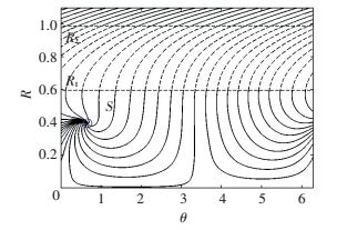
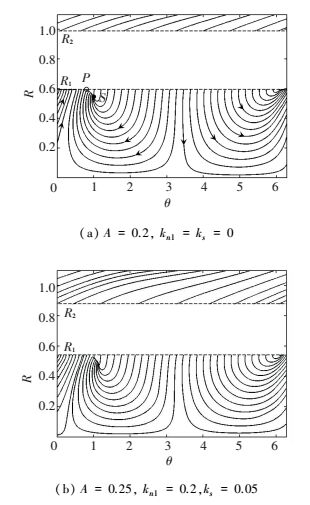
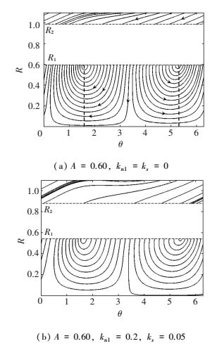
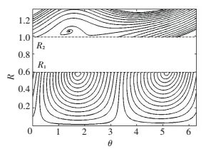
2.3 Analysis and DiscussionsAs mentioned in the above sections, we only draw attention to the effect of linear stiffness coefficient on response types of nonlinear system. For the sake of discussing the changes of response types in the reduced dynamics equations for various excitation amplitude of the systems represented by Eq.(1), phase portraits for the slow evolved system by Eq.(16) are constructed and shown by Figs. 5-8 (system parameters: ε=0.05, λ1=λ2=0.2, kn3=0.06). To be clear, system represented by Eq.(16) describes dynamic behavior over the stable regions of the slow invariant manifold. Results deviated from the above analysis as determined in Eq.(16) make it possible to depict the strongly quasi-periodic response (there are very low values R in the phase trajectories). The plotted phase trajectories only cover information of single ordinary fixed point in one period. And, we concentrate on the flow at two stable regions of the invariant manifold.
|
Figure 5 Phase trajectory of the system with a vibration absorber |
|
Figure 6 Phase trajectory of the system with a vibration absorber |
|
Figure 7 Phase trajectory of the system with a vibration absorber |
|
Figure 8 Phase trajectory of the system with a vibration absorber |
For the situation of 0 < A=0.15 < A11, a fixed point S which is end of the curves is marked on the phase trajectories in Fig. 5 (The solid and dash lines denote the stability and instability region, respectively.). It is obvious that there are no folded singularities (i.e. the final points of the "jump" on the fold lines R1 and R2). We can see that all phase trajectories are finally flowed to the fixed point S and the response of nonlinear system with an absorber is a steady response. Therefore, the relaxation oscillation and TET will not occur any more. In this case, the hysteretic vibration absorber is similar to the conventional nonlinear vibration absorber. But, the small mass ratio limited the efficiency of vibration suppression.
As amplitude of the excitation approaches the threshold A11, the SN bifurcation will occur on the lower boundary folded line R1. The phase trajectories for the case of A11 < A < A12 are depicted in Fig. 6(a) and 6(b). In Fig. 6(a), the phase portrait contains both an ordinary fixed point and lower bifurcation points for the system coupled to a nonlinear absorber without hysteretic nonlinearity, where the threshold values of the system represented by Eq.(17) are A11=0.176 and A12=0.984. For the system in which threshold values of the metal-rubber vibration absorber are A11=0.218 and A12=1.013, phase trajectories are depicted in Fig. 6(b). In this case, two different response regimes co-exist. One is steady-state response resulted from the ordinary point to which all phase trajectories are finally attracted, the other is strongly quasi-periodic response resulted from the folded singularities on the folded lines R1. More specifically, trajectories on the left of point P will be able to skip from the lower stable region, and finally lead to the relaxation oscillations. Hysteretic nonlinear parameters have effects only on the threshold and the flow direction of phase trajectories. But location of fixed point S in the phase portraits will remain unchanged.
Considering the one case of A11 < A < A12, the phase portraits are drawn for an increased amplitude A=0.60. As seen from Fig. 7(a) and 7(b), some qualitative changes of system dynamics behavior happen. The ordinary fixed point has vanished and the singular point on the folded lines become distant one from another. The distance between folded saddle and folded node depends upon phase angle θ and it can be calculated by Eq.(14). Similar to the previous case, hysteretic nonlinear parameters have effects only on the threshold and the flow direction of phase trajectories. However, response regimes of the system represented by Eq.(16) have underwent some changes. Due to the existence of the singular point on the folded lines, one of the response regime is weakly quasi-periodic response and the other is strongly quasi-periodic response. In this case, system hysteretic nonlinearity has an effect on the threshold values of external force.
For the another case of A>A12, the phase trajectories are plotted in Fig. 8. The ordinary fixed point on the upper boundary of the instability domain lead to steady response. The strongly quasi-periodic response also occurs in this case. Under a certain force, the initial conditions of the displacement and velocity of oscillators will determine the type of regimes response.
To summarize, the discussions above demonstrate that two qualitatively regimes co-exist in several cases. Those response types have characteristics of relaxation oscillations between different stable regions. The bifurcation caused by the external force brings about flow jumping from the lower stable regions to the upper stable regions and results in the relaxation oscillation in which the weakly and strongly quasi-periodic responses are included. The bilinear hysteretic nonlinearity has an influence on the threshold values of Eq.(17) which determine the type of regimes.
3 Numerical Examples and VerificationsIn this part, numerical examples are performed to verify the mentioned results. For the system in which a metal-rubber absorber is coupled, response of oscillators is calculated numerically via Runge-Kutta method for various forcing amplitudes.
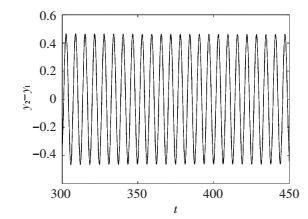
For the case of 0 < A=0.15 < A11, time response of relative displacement between two oscillators are depicted in Fig. 9. The steady-state response resulted from the existence of ordinary fixed point can be observed.
|
Figure 9 Time response of a steady-state periodic regime |
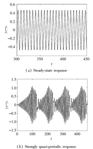
The next simulation is performed when the forcing amplitude A approaches the threshold A11. Two types of regimes, including the steady-state response (Fig. 10(a)) and strongly quasi-periodic response (Fig. 10(b)), may be excited. Obviously, the steady-state response and the strongly quasi-periodic response are resulted from the trivial fixed point and the singularities on the folded lines, respectively. The remaining system parameters are A=0.25, kn1=0.2, ks=0.05. But the initial conditions of Figs. 10(a) and 10(b) are different ([y1, y2,
|
Figure 10 Time response of a steady-state and strongly quasi-periodic response regime |
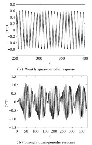
The simulation was performed for the amplitude values A=0.6 which is higher than the predicted threshold A11 but close to A12. The weakly quasi-periodic response and the strongly quasi-periodic response resulted from different initial conditions are depicted in Fig. 11(a) and Fig. 11(b), respectively. As mentioned above, the cause of this phenomenon is the "jump" between the lower region and the upper region in the phase portrait. The parameters are set as A=0.60, kn1=0.20, ks=0.05. The initial conditions are [y1, y2,
|
Figure 11 Time response of a weakly and strongly quasi-periodic response regime |
4 Conclusions
Dynamical mechanisms of a linear oscillator attached with a metal rubber vibration absorber under harmonica external force have been investigated. Based on the complex-averaging method, we deduce the functions of phase trajectories. Further, the analysis on phase trajectories of different external forces shows that two qualitatively regimes (strongly and weakly quasi-periodic response are included) exist in a bilinear hysteretic nonlinear energy sink. Response types of the investigated system determined by the amplitude of harmonica external excitation and related initial displacement conditions. Several numerical simulations are carried out to illustrate and verify the results.
| [1] |
Pham T T, Lamarque C H, Savadkoohi A T. Multi-resonance capturing in a two-degree-of-freedom system under two different harmonic excitations. Journal of Vibration and Control, 2011, 18(3): 451-466. DOI:10.1177/1077546311404268 ( 0) 0)
|
| [2] |
Vaurigaud B, Savadkoohi A T, Lamarque C H. Targeted energy transfer with parallel nonlinear energy sinks. Part I: Design theory and numerical results. Nonlinear Dynamics, 2011, 66(4): 763-780. DOI: 10.1007/s11071-011-9949-x.
( 0) 0)
|
| [3] |
Lamarque C H, Savadkoohi A T, Dimitrijevic Z. Dynamics of a linear system with time-dependent mass and a coupled light mass with non-smooth potential. Meccanica, 2014, 49(1): 135-145. DOI:10.1007/s11012-013-9778-8 ( 0) 0)
|
| [4] |
Al-Shudeifat M A. Highly efficient nonlinear energy sink. Nonlinear Dynamics, 2014, 76(4): 1905-1920. DOI:10.1007/s11071-014-1256-x ( 0) 0)
|
| [5] |
Manevitch L I. Dynamics of a linear oscillator coupled to a bistable light attachment: Analytical study. Journal of Applied Mechanics, 2014, 81(4): 041011. DOI:10.1115/1.4025150 ( 0) 0)
|
| [6] |
Starosvetsky Y, Gendelman O V. Attractors of harmonically forced linear oscillator with attached nonlinear energy sink. Ⅱ: Optimization of a nonlinear vibration absorber. Nonlinear Dynamics, 2007, 51(1/2): 47-57. DOI: 10.1007/s11071-006-9168-z.
( 0) 0)
|
| [7] |
Gendelman O V, Starosvetsky Y, Feldman M. Attractors of harmonically forced linear oscillator with attached nonlinear energy sink Ⅰ: Description of response regimes. Nonlinear Dynamics, 2008, 51(1): 31-46. DOI:10.1007/s11071-006-9167-0 ( 0) 0)
|
| [8] |
Weiss M, Chenia M, Savadkoohi A T, et al. Multi-scale energy exchanges between an elasto-plastic oscillator and a light nonsmooth system with external pre-stress. Nonlinear Dynamics, 2016, 83(1): 109-135. DOI:10.1007/s11071-015-2314-8 ( 0) 0)
|
| [9] |
Lee Y, Vakakis A, Bergman L, et al. Suppression aeroelastic instability using broadband passive targeted energy transfers, Part 1: theory. AIAA Journal, 2007, 45(3): 693-711. DOI:10.2514/1.24062 ( 0) 0)
|
| [10] |
Starosvetsky Y, Gendelman O V. Response regimes in forced system with non-linear energy sink: quasi-periodic and random forcing. Nonlinear Dynamics, 2011, 64(1): 177-195. DOI:10.1007/s11071-010-9856-6 ( 0) 0)
|
| [11] |
Bellizzi S, Cote R, Pachebat M. Responses of a two degree-of-freedom system coupled to a nonlinear damper under multi-forcing frequencies. Journal of Sound and Vibration, 2013, 332(7): 1639-1653. DOI:10.1016/j.jsv.2012.11.014 ( 0) 0)
|
| [12] |
Nahidi A, Younesian D. Novel control strategies for roll/pitch stabilization of tank wagons. Proceedings of the Institution of Mechanical Engineers Part F-Journal of Rail and Rapid Transit, 2016, 230(1): 151-164. DOI:10.1177/0954409714531410 ( 0) 0)
|
| [13] |
Kalmár-Nagy T, Shekhawat A. Nonlinear dynamics of oscillators with bilinear hysteresis and sinusoidal excitation. Physica D: Nonlinear Phenomena, 2009, 238(17): 1768-1786. DOI:10.1016/j.physd.2009.06.016 ( 0) 0)
|
| [14] |
Luo J, Wierschem N E, Fahnestock L A, et al. Realization of a strongly nonlinear vibration-mitigation device using elastomeric bumpers. Journal of Engineering Mechanics, 2014, 140(5): 70-75. ( 0) 0)
|
| [15] |
Dong X J, Peng Z K, Zhang W M, et al. Parametric characteristic of the random vibration response of nonlinear systems. Acta Mechanica Sinica, 2013, 29(2): 267-283. DOI:10.1007/s10409-013-0019-0 ( 0) 0)
|
| [16] |
Nguyen T A, Pernot S. Design criteria for optimally tuned nonlinear energy sinks—part 1: transient regime. Nonlinear Dynamics, 2011, 69(1): 1-19. DOI:10.1007/s11071-011-0242-9 ( 0) 0)
|
| [17] |
Gendelman O V, Sapsis T, Vakakis A F, et al. Enhanced passive targeted energy transfer in strongly nonlinear mechanical oscillators. Journal of Sound and Vibration, 2011, 330(1): 1-8. DOI:10.1016/j.jsv.2010.08.014 ( 0) 0)
|
| [18] |
Starosvetsky Y, Gendelman O V. Bifurcations of attractors in forced system with nonlinear energy sink: the effect of mass asymmetry. Nonlinear Dynamics, 2010, 59(4): 711-731. DOI:10.1007/s11071-009-9572-2 ( 0) 0)
|
| [19] |
Gourc E, Seguy S, Michon G, et al. Quenching chatter instability in turning process with a vibro-impact nonlinear energy sink. Journal of Sound and Vibration, 2015, 355: 392-406. DOI:10.1016/j.jsv.2015.06.025 ( 0) 0)
|
| [20] |
Bellet R, Cochelin B, Cote R, et al. Enhancing the dynamic range of targeted energy transfer in acoustics using several nonlinear membrane absorbers. Journal of Sound and Vibration, 2012, 331(26): 5657-5668. DOI:10.1016/j.jsv.2012.07.013 ( 0) 0)
|
 2017, Vol. 24


