Deployable structures are used for the ease of storage and transportation, and they are deployed into their operational configuration when required. Deployable structure presents contractility and developability characters, which are widely applied in various areas for ease of storage and transportation, such as aviation, aerospace, civil engineering, and so on[1-3]. Particularly on aerospace, since the space of vehicle is limited, and the deployable structures that need to carry become increasingly large, so deployable structures must be fold up to compression state for transportation to specified space location, after that develop to expectant work configuration for task. Since some special dynamic characteristics are presented during development process, it is necessary to research kinematics and dynamics behaviors of deployable structures.
Along with the development of aerospace technology, the dynamics of deployable institutions have became to be one of the hot research attracts that attracts many scholars[4-13]. Li et al.[14]established the stiffness model of deployable mechanism and carried out its simulation, Zhao et al.[15] investigated mechanism theory and application based on deployable mechanism of scissors unit. Chen et al.[16] executed the research on kinematics respect of deployable institutions consisted of Bricard fundamental unit. Based on the Moore-Penrose generalized matrix theory, Zhao[17] took the node's natural coordinates under Cartesian coordinates as unknown quantity, established dynamics general equation for deployable structure system, combined with generalized inverse matrix and multi-body dynamics theory to analyze the develop movement process of deployable institutions. Zhang et al.[18] adopted multi-body dynamics theory, combined with finite element method and Lagrange equation, established multi flexible-body dynamic equation for deployable structure. Yang et al.[19] utilized matrix condensation method to carry out statics analysis for a cylindrical folding mechanism, and using SIMP method to execute topology optimization design, so as to reduce the structure weight. Sun et al.[20] established dynamic equations of deployable structure based on Cartesian coordinate system, and using Runge-Kutta method to analyze the movement regularity of deployable institutions during develop process. Research stress of above references majorly focused on design theory and kinetic analysis of deployable mechanism, and at the same time, research related to the application of influence coefficient method on kinetic analysis process is relatively rare. In this paper, the influence coefficient method is adopted to analyze movement variation of planar deployable mechanism during motion process, the dynamic analysis procedure is simplified, of the process, the application range of this method is expanded, so as to display higher practical application value.
The displacement of unit-mechanism under generalized coordinates is solved by employing coordinate transformation, then the first order and second order influence coefficient are derived. The principle of virtual work is utilized to complete the analysis of dynamic characteristics, the explicit time formula related to displacement, velocity and acceleration under generalized coordinate is deduced, the explicit time formula related to displacement, velocity and acceleration under generalized coordinate is deduced, and based on D'alembert principle, using dynamic static method to calculate the constraint force of each hinge point. The displacement, velocity, acceleration and constraint force of all the hinged points are calculated, moreover, motion curve and constraint force curve are depicted. A numerical example is proposed and validated.
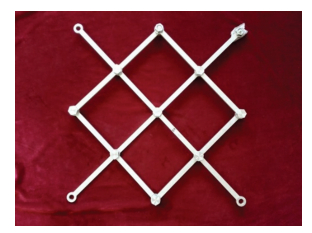
2 Dynamic Model of Deployable StructureThis paper takes plane unit that consists of four scissors units as research object. Fig. 1 shows the plane deployable structure including four scissors units. The plane unit of experimental deployable structure is presented in figures, and dynamic model of scissors unit deployable structure is built on the basis of Cartesian coordinate.
|
Figure 1 The experimental scissors unit plane deployable structure |
Scissor unit consists of two central mutually hinged and rotatable link members, a number of basic scissors link units are linked each other on terminal hinged point to compose basic piece unit plane deployable structure, and in this paper, taking a hinged planar deployable structure that has four scissors unit as an example to illustrate the deduction.
The schematic diagram of Scissor unit planar deployable mechanism is shown in Fig. 1, planar unit and serial number that assigned to hinged points of deployable structure is depicted.
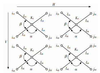
Taking the planar deployable mechanism that consists of four scissor units as an example, serial number of each hinged point is shown in Fig. 2, the first term of i or j subscript represents the scissors unit number, the second term of i or j subscript represents the hinged point number, α and β are geometric parameters, the first term of link length l subscript represents scissors unit number, the second term of link length l subscript represents link number.
|
Figure 2 Schematic diagram of scissor unit planar deployable structure |
The geometrical conditions(the length between point i11 to point j11) that this plane scissor units deployable structure needs to satisfy (in V direction) are:
| $ {i_{11}}{j_{11}} = {i_{12}}{j_{12}} = {i_{21}}{j_{21}} = {i_{22}}{j_{22}} $ | (1) |
Supposing that the links are rigid body on confi-guration design, thus
| $ {i_{12}}{j_{12}} = {i_{21}}{j_{21}} $ | (2) |
Then it is concluded as:
| $ l_{12}^2 + l_{14}^2 - 2{l_{12}}{l_{14}}\cos \alpha = l_{21}^2 + l_{23}^2 - 2{l_{21}}{l_{23}}\cos \alpha $ | (3) |
Due to the arbitrariness of α during developing process, it is derived:
| $ \left\{ \begin{array}{l} l_{12}^2 + l_{14}^2 = l_{21}^2 + l_{23}^2\\ {l_{12}}{l_{14}} = {l_{21}}{l_{23}} \end{array} \right. $ | (4) |
The similar operation can be done and obtained the following expressions, giving by:
| $ \left\{ \begin{array}{l} l_{32}^2 + l_{34}^2 = l_{41}^2 + l_{43}^2\\ {l_{32}}{l_{34}} = {l_{41}}{l_{43}} \end{array} \right. $ | (5) |
| $ \left\{ \begin{array}{l} l_{13}^2 + l_{14}^2 = l_{31}^2 + l_{32}^2\\ {l_{13}}{l_{14}} = {l_{31}}{l_{32}} \end{array} \right. $ | (6) |
| $ \left\{ \begin{array}{l} l_{23}^2 + l_{24}^2 = l_{41}^2 + l_{42}^2\\ {l_{23}}{l_{24}} = {l_{41}}{l_{42}} \end{array} \right. $ | (7) |
Simultaneous solving the above four equations, it is obvious that there are multiple solutions for 16 unknown variables and 8 equations. This article selects a case as an example to carry out analysis, namely the lengths l of each link are equivalent conditions.
3 Dynamics Investigation 3.1 Influence Coefficient MethodMechanism kinematic influence coefficient is proposed by Prof. Tesar and Dufy etc.[21-22], and the influence coefficient method involves establishing 1-step exercise coefficient matrix and 2-step exercise coefficient matrix, the former refers to Jacobian matrix, and the latter one refers to Hessian matrix. The Kinematic influence coefficient highly abstractly reflects the essence of mechanism kinematics and dynamics, and expresses velocity analysis, acceleration analysis, error analysis and stress analysis in the form of a simple style. Moreover, it is convenient to in-depth research mechanism's special configuration, the working space of the robot arm and operability research, and do not need a great deal of calculation.
As a kind of mechanism with complex geometrical shape, the planar deployable mechanism not only is multi-closed-loop structure that contains a great deal of redundant constraints, but also is a series-parallel structure. The fact that a linkage simultaneously joins with multiple linkages causes numerous over-constraints exist in a planar deployable mechanism. If adopting traditional dynamic analysis method, then the building process of constraint equation is more complicated. When using the influence coefficient method, it is convenient to analyze direct kinetic relationship between any two linkages, to find out the speed-acceleration expression, and various forms of solution can be mutually transformed. The more complex of mechanism, the more superior of influence coefficient method can be displayed. Therefore, the influence coefficient method could be a relatively effective mathematic tool for the research of planar deployable mechanism, which could clarify and simplify the analysis process of planar deployable mechanism[23].
For the deployable structure showed in Fig. 1, if exercise is input by single-degree-of-freedom kinematic pair, which can be revolute pairs or movement pairs, then the position of mechanism's any pole is determined. Pole's position can be described by hinged point coordinates and pole's angular position, using Ui[Φi, Xi, Yi]T and Φi, Xi, Yi to respectively represent the angular position Φ under reference frame selected for defining the ith linkage's position and the x, y coordinate of reference points, they are the function of input motion parameters φ1, φ2, …, φN, then derive:
| $ U = f\left( {{\varphi _1}{\varphi _2} \cdots {\varphi _N}} \right) $ | (8) |
Derivative of U with respect to time, obtain any point's speed of component:
| $ \mathit{\boldsymbol{\dot U = }}\left[ \mathit{\boldsymbol{J}} \right]\mathit{\boldsymbol{\dot \varphi }} $ | (9) |
where [J] is called the first order influence coefficient matrix or Jacobian matrix.
| $ \begin{array}{*{20}{c}} {\left[ \mathit{\boldsymbol{J}} \right] = {{\left[ {\frac{{\partial U}}{{\partial {\varphi _1}}}\frac{{\partial U}}{{\partial {\varphi _2}}} \cdots \frac{{\partial U}}{{\partial {\varphi _N}}}} \right]}_{1 \times N}} = }\\ {\left[ {\begin{array}{*{20}{c}} {\frac{{\partial {f_1}}}{{\partial {\varphi _1}}}}& \cdots &{\frac{{\partial {f_1}}}{{\partial {\varphi _N}}}}\\ \vdots &{}& \vdots \\ {\frac{{\partial {f_3}}}{{\partial {\varphi _1}}}}& \cdots &{\frac{{\partial {f_3}}}{{\partial {\varphi _N}}}} \end{array}} \right] \in {{\bf{R}}^{3 \times N}}}\\ {\mathit{\boldsymbol{\dot \varphi }} = \left[ {{{\dot \varphi }_1}{{\dot \varphi }_2} \cdots {{\dot \varphi }_N}} \right]_{N \times 1}^{\rm{T}}} \end{array} $ |
Derivative of
| $ \mathit{\boldsymbol{\ddot U = }}{{\mathit{\boldsymbol{\dot \varphi }}}^{\rm{T}}}\left[ \mathit{\boldsymbol{H}} \right]\mathit{\boldsymbol{\dot \varphi }} + \left[ \mathit{\boldsymbol{J}} \right]\mathit{\boldsymbol{\ddot \varphi }} $ | (10) |
where [H] is called the second order influence coefficient matrix or Hessian matrix, and
| $ \begin{array}{*{20}{c}} {\left[ \mathit{\boldsymbol{H}} \right] = \left[ {\begin{array}{*{20}{c}} {\frac{{{\partial ^2}U}}{{\partial {\varphi _1}\partial {\varphi _1}}}}& \cdots &{\frac{{{\partial ^2}U}}{{\partial {\varphi _1}\partial {\varphi _N}}}}\\ \vdots &{}& \vdots \\ {\frac{{{\partial ^2}U}}{{\partial {\varphi _N}\partial {\varphi _1}}}}& \cdots &{\frac{{{\partial ^2}U}}{{\partial {\varphi _N}\partial {\varphi _N}}}} \end{array}} \right]}\\ {\mathit{\boldsymbol{\ddot \varphi = }}\left[ {{{\ddot \varphi }_1}{{\ddot \varphi }_2} \cdots {{\ddot \varphi }_N}} \right]_{N \times 1}^{\rm{T}}} \end{array} $ |
Before the research of kinematics and dynamics of mechanism, proper fixed coordinate system and movement coordinate system should be established. If the selected coordinate system is appropriate, not only the mechanism motion can be described clearly and concisely for the further analysis, and the derivation process of motion equation can also be simplified.
The simplified form of kinematics and dynamics equations and the convenience of solving process can be used to reduce the complicity of equation solving, and shorten the calculation time.
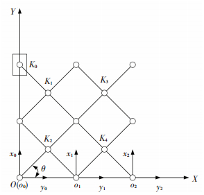
Taking the scissors unit deployable structure shown in Fig. 3 as an example, assuming pole's length are equivalent, and when deploying the mechanism, which connects the support structure through revolute pairs at i12, i22, j22 and j42, and articulates with a slide block K0 by revolute pairs, then the slide block moves along the OY axis, and mechanism deploys along the OX direction. The origin of fixed coordinate system ∑XOY is located in the center of articulated point i22, OX axis is consistent with the direction of i22j22, OY axis is established according to the principle of Cartesian coordinates. The fixed coordinate system of movement unit ∑xtoyt is established for each unit mechanism t(t=2, 4, 6, …, N), OX axis is consistent with the direction of it2jt2, OY axis is established according to principle of Cartesian coordinates. According to above principle of Cartesian coordinates, when t=2, coordinate system of movement unit ∑xtoyt and fixed coordinate system ∑XOY are coincided.
|
Figure 3 Scissors unit planar deployable structure |
From the geometrical relationship of scissors unit deployable structure and coordinate, which is established according to principle of Cartesian coordinates, it can be seen that since the articulated points connects i11i12, i21i22, i31i32, i41i42… are parallel to each other, then coordinate axis o0x0, o1x1, o2x2… are parallel to each other too, and since the articulated points i22, j22, i42, j42… coincide with OX axis, then coordinate axis o0x0, o1x1, o2x2… coincide with OX axis. For any deploy angle θ, the coordinate transformation matrix from coordinate system of movement unit coordinate system ∑xtoyt to fixed coordinate system can be described by formula (11):
| $ {\mathit{\boldsymbol{R}}_{ot}} = \left[ {\begin{array}{*{20}{c}} 1&0\\ 0&1 \end{array}} \right] $ | (11) |
Because the configuration of planar deployable structure's each unit is the same, thus:
| $ {i_{\left( {2t} \right)2}}{j_{\left( {2t} \right)2}} = l\cos \left( \theta \right)\left( {t = 1,2, \cdots ,N} \right) $ | (12) |
The origin of movement unit coordinate system ∑xtoyt corresponding to the x point of fixed coordinate system ∑XOY, and x's coordinate is:
| $ {x_{ot}} = t{i_{\left( {2t} \right)2}}{j_{\left( {2t} \right)2}} = lt\cos \theta $ | (13) |
The coordinate transformation matrix from coordinate system ∑xtoyt to fixed coordinate system ∑XOY is:
| $ {\mathit{\boldsymbol{T}}_{ot}} = \left[ {\begin{array}{*{20}{c}} {{x_{o\left( {t - 1} \right)}}}\\ 0 \end{array}} \right] = \left[ {\begin{array}{*{20}{c}} {2tl\cos \theta }\\ 0 \end{array}} \right] = t{\mathit{\boldsymbol{T}}_o} $ | (14) |
where, To=[2lcos θ 0]T, To's the first and second order derivative derivation of θ respectively is:
| $ {\left[ {{{\mathit{\boldsymbol{\dot T}}}_o}} \right]_\theta } = - 2l{\left[ {\begin{array}{*{20}{c}} {\sin \theta }&0 \end{array}} \right]^{\rm{T}}} $ | (15) |
| $ {\left[ {{{\mathit{\boldsymbol{\ddot T}}}_o}} \right]_{\theta \theta }} = - 2l{\left[ {\begin{array}{*{20}{c}} {\cos \theta }&0 \end{array}} \right]^{\rm{T}}} $ | (16) |
Using formula (14) can acquire Tot's first and second order derivative derivation of θ respectively, given as:
| $ {\left[ {{{\mathit{\boldsymbol{\dot T}}}_{ot}}} \right]_\theta } = t{\left[ {{{\mathit{\boldsymbol{\dot T}}}_o}} \right]_\theta } $ | (17) |
| $ {\left[ {{{\mathit{\boldsymbol{\ddot T}}}_{ot}}} \right]_{\theta \theta }} = t{\left[ {{{\mathit{\boldsymbol{\ddot T}}}_o}} \right]_{\theta \theta }} $ | (18) |
Assuming orMt represents M point's radius vector of unit mechanism in fixed coordinate system ∑xtoyt, and trMt represents M point's radius vector of unit mechanism in movement unit coordinate system, then
| $ {}^o\mathit{\boldsymbol{r}}_M^t = {\mathit{\boldsymbol{T}}_{ot}} + {\mathit{\boldsymbol{R}}_{ot}}{}^t\mathit{\boldsymbol{r}}_M^t = {\mathit{\boldsymbol{T}}_{ot}} + {}^t\mathit{\boldsymbol{r}}_M^t $ | (19) |
Using formula (19) to get the first and second order derivation of time, can obtain the velocity and acceleration of point M:
| $ {}^ov_M^t = {}^o\dot r_M^t = {{\dot T}_{ot}} + {}^o\dot r_M^t $ | (20) |
| $ {}^oa_M^t = {}^o\ddot r_M^t = {{\ddot T}_{ot}} + {}^t\ddot r_M^t $ | (21) |
According to coordinate translation variables and M point's coordinate, it is available that
| $ v_M^t = {}^oJ_{Mt}^t\omega $ | (22) |
| $ {}^oa_M^t = {}^oJ_{Mt}^t\delta + {}^oH_{Mt}^t{\omega ^2} $ | (23) |
where
| $ \begin{array}{l} {}^oJ_{Mt}^t = v_M^t/\omega = {\rm{d}}\left( {{{\dot T}_{ot}} + {}^t\dot r_M^t} \right)/{\rm{d}}\theta = \\ \;\;\;\;\;\;\;\;\;\;{\left[ {{{\dot T}_{ot}}} \right]_\theta } + {\left[ {{}^t\dot r_M^t} \right]_\theta } = t{\left[ {{{\dot T}_o}} \right]_\theta } + {\left[ {{}^t\dot r_M^t} \right]_\theta } \end{array} $ | (24) |
| $ \begin{array}{l} {}^oH_{Mt}^t = {\rm{d}}\left( {{}^oJ_{Mt}^t} \right)/{\rm{d}}\theta = {{\rm{d}}^2}\left( {{{\dot T}_{ot}} + {}^t\dot r_M^t} \right)/{\rm{d}}{\theta ^2} = \\ \;\;\;\;\;\;\;\;\;\;{\left[ {{{\dot T}_{ot}}} \right]_{\theta \theta }} + \left[ {{}^t\dot r} \right]_{M\theta \theta }^t = t{\left[ {{{\dot T}_o}} \right]_{\theta \theta }} + {\left[ {{}^t\dot r_M^t} \right]_{\theta \theta }} \end{array} $ | (25) |
oJMtt is the first order influence coefficient of line movement, oHMtt is the second order influence coefficient of line movement. Where,
| $ {\left[ {{}^t\dot r_M^t} \right]_\theta } = {\rm{d}}\left( {{}^t\dot r_M^t} \right)/{\rm{d}}\theta ,{\left[ {{}^t\dot r_M^t} \right]_{\theta \theta }} = {{\rm{d}}^2}\left( {{}^t\dot r_M^t} \right)/{\rm{d}}{\theta ^2} $ |
oJMtt represents the sum of coordinate translation transformation matrix Tot and the coordinate trMt of point M, M is located at movement unit coordinate system, oJMtt and oHMtt are function of θ, and are irrelative with velocity and acceleration of mechanism.
According to the above reasons, the displacement, velocity and acceleration of planar deployable structure's any point can be obtained. In other words, it only needs to calculate the displacement, velocity and acceleration of five points: i11, i12(i21), i22, j32(j21) and j22.
3.3 Dynamic AnalysisThe planar deployable structure is articulated with a slide block K0 by revolute pairs at i11, the slide block can move along OY axis, and the planar deployable structure can deploy along OX direction.
Assume the center of mass of component i22K21j21, j22K22i21 is located at K21, K22 point respectively, then inertia force QFt and moment of inertia QTt of unit mechanism t can be represented by:
| $ \left[ {Q_F^t} \right] = - {m^t}\left[ {{}^oa_K^t} \right] $ | (26) |
| $ \left[ {Q_{\rm{T}}^t} \right] = - {\mathit{\boldsymbol{J}}^t}\left[ {{\delta ^t}} \right] $ | (27) |
where, [QFt]=[Qxt Qyt]T and QxtQyt are the inertia force's components of unit mechanism t in x and y direction, mt=m1t+m2t is the mass of unit mechanism t, m1tm2t are the mass of component i22K21j21, j22K22i21 respectively. [QTt]=[QT1t, QT2t]T and QT1t, QT2t are the moment of inertia of component i22K21j21, j22K22i21 respectively,
| $ \Delta r_{K2}^t = {}^oG_{K2r}^t\Delta \theta $ | (28) |
The virtual displacement Δφt of unit t's component i22K21j21, j22K22i21 can be expressed by:
| $ \Delta {\varphi ^t} = {}^oG_\theta ^t\Delta \theta $ | (29) |
The virtual work calculated by inertia force and mo-ment of inertia of unit t can be represented by:
| $ \mathit{\boldsymbol{W}}_Q^t = {\left[ {Q_{\rm{T}}^t} \right]^{\rm{T}}}\Delta {\varphi ^t} + {\left[ {Q_F^t} \right]^{\rm{T}}}\Delta r_{K2}^t $ | (30) |
Through the relation between the displacementin y direction of slide block at hinging point i11, which is solved earlier in this paper, and θ, then the variation is:
| $ {\Delta ^o}y_i^0 = 2l\cos \left( {\theta /2} \right)\Delta \theta $ | (31) |
If signing the force exerted by slide block as F, then the virtual work is:
| $ {W_F} = F{\Delta ^o}y_i^0 $ | (32) |
According to the principle of virtual work,
| $ \sum\limits_{t = 0}^{N - 1} {W_Q^t + {W_F} = 0} $ | (33) |
Substitute equations in formula (33), it can be obtained and given by:
| $ \delta = \frac{{2Fl\cos \left( {\theta /2} \right) - {\omega ^2}\sum\limits_{t = 0}^{N - 1} {{m^t}\left( {t\left[ {{T_o}} \right]_{\theta \theta }^{\rm{T}} + \left[ {{}^tr_{K2}^t} \right]_{\theta \theta }^{\rm{T}}} \right)\left( {t{{\left[ {{T_o}} \right]}_\theta } + {{\left[ {{}^tr_{K2}^t} \right]}_\theta }} \right)} }}{{\sum\limits_{t = 0}^{N - 1} {{{\left[ {{}^oG_\theta ^t} \right]}^{\rm{T}}}{J^{t0}}G_\theta ^t} + \sum\limits_{t = 0}^{N - 1} {{m^t}\left( {t\left[ {{T_o}} \right]_\theta ^{\rm{T}} + \left[ {{}^tr_{K2}^t} \right]_\theta ^{\rm{T}}} \right)\left( {t{{\left[ {{T_o}} \right]}_\theta } + {{\left[ {{}^tr_{K2}^t} \right]}_\theta }} \right)} }} $ | (34) |
Since 0rK20=1rK21=…=N-1rK2N-1, so unifying them by rK2, assume the mass and rotational inertia of all unit mechanism are equivalent, and represent by m and J respectively. Substitute equations in formula (34), then
| $ \delta = \frac{{24Fl\cos \left( {\theta /2} \right) - N\left( {N + 1} \right)\left( {N - 1} \right)m{\omega ^2}{l^2}\sin \theta }}{{3NJ + 3mN{l^2} + 4N\left( {N + 1} \right)\left( {N - 1} \right)m{l^2}{{\sin }^2}\left( {\theta /2} \right)}} = \frac{{24Fl\cos \left( {\theta /2} \right) - A{\omega ^2}\sin \theta }}{{B + 4A{{\sin }^2}\left( {\theta /2} \right)}} $ | (35) |
where, A=N(N+1)(N-1), B=3 NJ. Formula (35) is a second-order differential equation, after the reduction of order, using Runge-Kutta method to execute numerical calculation and obtain the time curve of generalized coordinates and generalized velocity, substitute them in above equations, and calculate the displacement, velocity and acceleration of each component and hinge point.
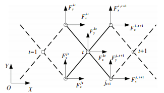
Dynamics analysis of planar deployable structure is completed in foregoing part, and the next step is to calculate constraint force of each hinge point during deploy process. For the sake of research convenience, selecting the scissors unit mechanism of force planar deployable structure i22K21j21, j22K22i21 as research object, in which, the constraint force of each hinge point is shown in Fig. 4, in order to simple marking, using Fxjt represents the constraint force of unit mechanism in x direction that sustained on hinge jt, and other symbols are taken same manner. The symbols Fxkt, Fykt represent the force that component j22K22i21 exerts on component i22K21j21 in unit mechanism.
|
Figure 4 The force diagram of scissors unit mechanism |
According to the D'alembert's principle, ad-opting dynamic static method to create the balance equation respectively for the component i22K21j21, j22K22i21 and solving, get formula
| $ {F^t} = J{L^t} + q{Q^t} $ | (36) |
where,
| $ \begin{array}{*{20}{c}} {{\mathit{\boldsymbol{F}}^t} = {{\left[ {\begin{array}{*{20}{c}} {F_x^{jt}}&{F_y^{jt}}&{F_x^{it}}&{F_y^{it}} \end{array}} \right]}^{\rm{T}}}}\\ {{\mathit{\boldsymbol{L}}^t} = {{\left[ {\begin{array}{*{20}{c}} {F_x^{j,t + 1}}&{F_y^{j,t + 1}}&{F_x^{i,t + 1}}&{F_y^{i,t + 1}} \end{array}} \right]}^{\rm{T}}}} \end{array} $ |
and Ft represent the driven force of unit mechanism t, which is the load of unit t-1, and Lt represents the load of unit mechanism t, which is the driven force of unit t+1, they need to satisfy the relationship below:
| $ {\mathit{\boldsymbol{L}}^{t - 1}} = - {\mathit{\boldsymbol{F}}^t} $ | (37) |
Qt=[Qx1t Qy1t Qx2t Qy2t QT1t QT2t]T is the inertia force vector of unit mechanism, J and q are coefficient matrix,
| $ \mathit{\boldsymbol{J = }}\left[ {\begin{array}{*{20}{c}} { - 1}&{ - \cot \left( {\frac{\theta }{2}} \right)}&0&{ - \cot \left( {\frac{\theta }{2}} \right)}\\ { - \tan \left( {\frac{\theta }{2}} \right)}&{ - 1}&{ - \tan \left( {\frac{\theta }{2}} \right)}&0\\ 0&{\cot \left( {\frac{\theta }{2}} \right)}&{ - 1}&{\cot \left( {\frac{\theta }{2}} \right)}\\ {\tan \left( {\frac{\theta }{2}} \right)}&0&{\tan \left( {\frac{\theta }{2}} \right)}&{ - 1} \end{array}} \right] $ |
| $ \mathit{\boldsymbol{q = }} - \frac{1}{2}\left[ {\begin{array}{*{20}{c}} 1&{\cot \left( {\frac{\theta }{2}} \right)}&1&{\cot \left( {\frac{\theta }{2}} \right)}&{\csc \left( {\frac{\theta }{2}} \right)/l}&{\csc \left( {\frac{\theta }{2}} \right)/l}\\ {\tan \left( {\frac{\theta }{2}} \right)}&1&{\tan \left( {\frac{\theta }{2}} \right)}&1&{ - \sec \left( {\frac{\theta }{2}} \right)/l}&{\sec \left( {\frac{\theta }{2}} \right)/l}\\ 1&{ - \cot \left( \theta \right)}&1&{ - \cot \left( {\frac{\theta }{2}} \right)}&{ - \csc \left( {\frac{\theta }{2}} \right)/l}&{ - \csc \left( {\frac{\theta }{2}} \right)/l}\\ { - \tan \left( {\frac{\theta }{2}} \right)}&1&{ - \tan \left( {\frac{\theta }{2}} \right)}&1&{\sec \left( {\frac{\theta }{2}} \right)/l}&{ - \sec \left( {\frac{\theta }{2}} \right)/l} \end{array}} \right] $ |
In hinge k, the force on component i22K21j21 exerted by component i22K21j21 is:
| $ \mathit{\boldsymbol{F}}_k^t = {\mathit{\boldsymbol{J}}_k}{\mathit{\boldsymbol{L}}^t} + {\mathit{\boldsymbol{q}}_k}{\mathit{\boldsymbol{Q}}^t} $ | (38) |
where, Jkqk are coefficient matrix, meet formula:
| $ {\mathit{\boldsymbol{J}}_k} = \left[ {\begin{array}{*{20}{c}} 1&{\cot \left( {\theta /2} \right)}&{ - 1}&{\cot \left( {\theta /2} \right)}\\ {\tan \left( {\theta /2} \right)}&1&{\tan \left( {\theta /2} \right)}&{ - 1} \end{array}} \right] $ |
| $ {\mathit{\boldsymbol{q}}_k} = \frac{1}{2}\left[ {\begin{array}{*{20}{c}} { - 1}&{\cot \left( {\frac{\theta }{2}} \right)}&1&{\cot \left( {\frac{\theta }{2}} \right)}&{\csc \left( {\frac{\theta }{2}} \right)/l}&{\csc \left( {\frac{\theta }{2}} \right)/l}\\ {\tan \left( {\frac{\theta }{2}} \right)}&{ - 1}&{\tan \left( {\frac{\theta }{2}} \right)}&1&{ - \sec \left( {\frac{\theta }{2}} \right)/l}&{\sec \left( {\frac{\theta }{2}} \right)/l} \end{array}} \right] $ |
The magnitude |Fkt| of Fkt represents the con-straint force of hinge kt.
When θ=0, π, 2π, 3π, …, tan (θ/2), cot(θ/2), sec(θ/2) and csc(θ/2) are infinity, matrix J, q, Jk, qk are pointless, thus formula (36) and (38) are no longer valid, mechanism respectively corresponds to two different kinds of singular configuration, and leads to the degrees of freedom to be greater than 1, movement is uncertain. When θ=0, 2π, …, hinge point it and jt coincide, two components overlap in the same unit, all units connect successively and coincide with x axis; when θ=π, 3π, …, hinge point i0, i1, i2, …, iN-1 coincide, j0, j1, j2, …, jN-1 coincide, k1, k2, …, kN-1 coincide, two components of each unit both coincide with y axis.
If the external applied load of unit N-1 on hinge iN, jN is represented by LN-1, substitute it in formula (36) and (38), solve and obtain constraint force FN-1, FkN-1 of hinge iN-1, jN-1, substitute FN-1 in formula (36), (37) and (38), get the solution of FN-2, FkN-2. Execute recursive successively and solve constraint force of each hinge.
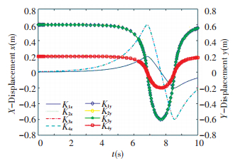
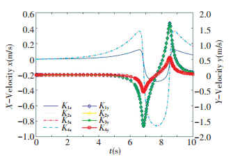
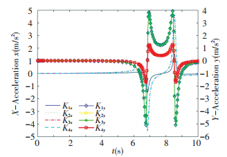
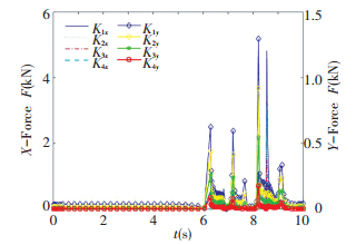
4 Numerical ExampleTaking the scissors unit planar deployable structure as an example, adopt pole length l=500 mm, r=2 mm, pole mass m=1 kg, density ρ=7 800 kg/m3, driven force acting in y axis direction through hinge point i11 is F=-40 N, the initial value of fixed coordinate system is θ0=(π-0.1) rad, displace-ment, velocity and acceleration of each hinge point and constraint force of articulated link chain are shown in Figs. 5-8.
|
Figure 5 The displacement curve of hinge point in x and y direction |
|
Figure 6 The velocity curve of hinge point in x and y direction |
|
Figure 7 The acceleration curve of hinge point in x and y direction |
|
Figure 8 The constraint force curve of hinge point in x and y direction |
From the analysis of Fig. 8, after exerting a driving force F on hinge point i11 along y axis, surface deployable institutions complete development with varying acceleration. When configuration angle θ ≫ 0, the angular acceleration of each component approximate to constant, the development approximate to uniform angular acceleration, the linear acceleration of each hinge point is nearly unchanged, approximate to uniformly accelerated motion, the constraint force of each hinge point approximates to be constant.
When the configuration angle θ of unit mechanism is approaching to π, angular acceleration of each component increases sharply, the angular velocity changes quickly, linear acceleration of each hinge point also increases sharply, linear velocity changes quickly, and causes comparatively large constraint force on each hinge.
It can be concluded that, for the scissors unit institutions, the variation of displacement, velocity and acceleration of hinge point trend to be consistent, this phenomenon explains that the planar deployable unit of scissors mechanism displays consistent dynamic characteristics.
5 ConclusionsThis paper adopts influence coefficient method to analyze the dynamic characteristics for planar deployable mechanism.
Based on the cartesian coordinate system, the dynamics analysis model of deployable mechanism is established, through coordinate transformation, the displacement and movement influence coefficient under generalized coordinates of each unit mechanism are obtained; the principle of virtual work is applied to complete dynamic characteristics analysis; based on the D'Alembert's principle, combined with dynamic static method, calculated the constraint force for each hinge; finally, dynamic analysis and calculating examples are presented to verify the effectiveness of proposed method in this paper. Utilizing the method presented in this paper can simplify dynamic analysis procedure, and expand the application range of this method, thus can be provided with higher practical application value.
From above research and analysis, the dynamic characteristics of surface deployable institutions during develop process can be effectively predicted, and this research would facilitate engineering application. In the following study, the varying driving force can be considered to help avoid motion mutation during the moving process of orbiting spacecraft, which can affect motion attitude, so as to prolong the service life of spacecraft.
| [1] |
Pellegrino S. Deployable Structures. New York: Springer, 2001, 2-15.
( 0) 0)
|
| [2] |
Gantes C J. Deployable Structures: Analysis and Design. Southampton: Wit Press, 2001, 26-29.
( 0) 0)
|
| [3] |
Sokolowski W M, Tan S C. Advanced self-deployable structures for space applications. Journal of Spacecraft & Rockets, 2012, 44(4): 750-754. DOI:10.2514/1.22854 ( 0) 0)
|
| [4] |
Fischer A, Pellegrino S. Interaction between gravity compensation suspension system and deployable structure. Journal of Spacecraft and Rockets, 2015, 37(1): 93-99. ( 0) 0)
|
| [5] |
Puig L, Barton A, Rando N. A review on large deployable structures for astrophysics missions. Acta Astronautica, 2010, 67(1/2): 12-26. DOI:10.1016/j.actaastro.2010.02.021 ( 0) 0)
|
| [6] |
Li Duanling, Zhang Zhonghai, Yu Zhen. Kinematic characteristic analysis of spherical scissors deployable mechanisms. Journal of Mechanical Engineering, 2013, 49(13): 1-7. DOI:10.3901/JME.2013.13.001 ( 0) 0)
|
| [7] |
Zhao Jinshan, Wang Jianyi, Chu Fulei, et al. Structure synthesis and statics analysis of a foldable stair. Mechanism & Machine Theory, 2011, 46(7): 998-1015. DOI:10.1016/j.mechmachtheory.2011.02.001 ( 0) 0)
|
| [8] |
Akgüna Y, Gantes C J, Sobekd W, et al. A novel adaptive spatial scissor-hinge structural mechanism for convertible roofs. Engineering Structures, 2011, 33(4): 1365-1376. DOI:10.1016/j.engstruct.2011.01.014 ( 0) 0)
|
| [9] |
Li Bo, Wang Sanmin, Yuan Ru, et al. Dynamics analysis of linear array deployable structure based on symmetrical scissor-like element. Proceedings of the 5th International Conference on Electrical Engineering and Automatic Control. Berlin: Springer, 2016. 1163-1171. DOI: 10.1007/978-3-662-48768-6_130.
( 0) 0)
|
| [10] |
Tur M, Garcí E, Baeza L, et al. A 3D absolute nodal coordinate finite element model to compute the initial configuration of a railway catenary. Engineering Structures, 2014, 71(1): 234-243. DOI:10.1016/j.engstruct.2014.04.015 ( 0) 0)
|
| [11] |
Li Bo, Wang Sanmin, Zhi Changjian, et al. Analytical and numerical study of the buckling of planar linear array deployable structures based on scissor-like element under its own weight. Mechanical Systems & Signal Processing, 2016, 83: 474-488. DOI:10.1016/j.ymssp.2016.06.025 ( 0) 0)
|
| [12] |
Zhi Changjian, Wang Sanmin, Sun Yuantao, et al. Kinematic and dynamic characteristics analysis of Bennett' s linkage. Journal of Harbin Institute of Technology (New Series), 2015, 22(3): 95-100. ( 0) 0)
|
| [13] |
Wang Wei. Assembling and Analysis of Large Special Deployable and Networks Based on Bennett Linkage. Shenzhen: Harbin Institute of Technology(Shenzhen), 2011. (in Chinese)
( 0) 0)
|
| [14] |
Li Duanlin, Bai Lin. Deployable Structure Stiffness Model Building and Simulation Based on Scissor-like Element. Beijing: Sciencepaper Online. http://www.paper.edu.cn/releasepaper/content/201601-366. (in Chinese)
( 0) 0)
|
| [15] |
Zhao Jinshan, Chu Fulei, Feng Zhijin. The mechanism theory and application of deployable structures based on SLE. Mechanism & Machine Theory, 2009, 44(2): 324-335. DOI:10.1016/j.mechmachtheory.2008.03.014 ( 0) 0)
|
| [16] |
Chen Yan, You Zhou, Tarnai Tibor. Threefold-symmetric Bricard linkages for deployable structures. International Journal of Solids and Structures, 2005, 42(8): 2287-2230. DOI:10.1016/j.ijsolstr.2004.09.014 ( 0) 0)
|
| [17] |
Zhao Mengliang. Dynamic Theory Analysis, Simulation and Experiments for Deployment Process of Deployable Space Structures. Hangzhou: Zhejiang University, 2007. 16-52 (in Chinese)
( 0) 0)
|
| [18] |
Zhang Chong, Wang Sammin, Yuan Ru. Onelastodynamic characteristics of space deployable mechanism. Mechanical Science and Technology for Aerospace Engineering, 2007(11): 1479-1482. ( 0) 0)
|
| [19] |
Yang Yi, Ding Xilun. Analysis and topology optimization of deployable mechanism based on pantograph. China Mechanical Engineering, 2010, 21(2): 184-189. ( 0) 0)
|
| [20] |
Sun Yuantao, Wang Sanmin, Liu Xia. Dynamics research of linear array deployable structures based on structure of scissor-like element. China Mechanical Engineering, 2012, 23(24): 2917-2919. ( 0) 0)
|
| [21] |
Thomas M, Tesar D. Dynamic modeling of serial manipulator arms. Journal of Dynamic Systems Measurement & Control, 1982, 104(3): 218-228. DOI:10.1115/1.3139701 ( 0) 0)
|
| [22] |
Mohamed M G, Duffy J. A direct determination of the instantaneous kinematics of fully parallel robot manipulators. Journal of Mechanisms, Transmissions, and Automation in Design, 1985, 107(2): 226-229. DOI:10.1115/1.3258713 ( 0) 0)
|
| [23] |
Murray R M, Sastry S S, Zexiang L. A mathematical introduction to robotic manipulation. Boca Raton: CRC Press, 1994, 61-73.
( 0) 0)
|
 2017, Vol. 24


