SRUHSC frame structures have been readily available for applications in ultra high rise buildings because of their various advantages such as superior durability, high strength and economic efficiency[1]. However, due to the brittleness and sectional failure characteristics of ultra high-strength concrete, aggregate biting weakens significantly once cracking of the concrete has occurred[2]. Current requirements, which were originally derived from experimental results on reinforced normal concrete, are not suited for SRUHSC joints. In addition, current code of each nation about beam-column joint design has different interpretation about the effect of axial compression ratio on seismic behavior of the specimens[3-5]. For example, JGJ-138 and SNZ-3101 consider that increase of axial compression ratio can improve the shear capacity of the structures. While ACI-318 does not treat axial compression ratio as an affecting factor that influences the shear capacity and deformation.Lin et al.[6] has conducted experiments to study the seismic behavior of reinforced concrete joints with various axial compression ratio selected as 0, 0.1, 0.2, 0.3, 0.4 respectively. It shows that: 1) when axial compression ratio increased from 0 to 0.1, axial compression ratio did not influence obviously to the shear capacity of the specimens; 2) when axial compression ratio increased from 0.1 to 0.3, the shear capacity of the specimens increased; 3) when axial compression ratio increased from 0.3 to 0.4, the shear capacity of the specimens dropped.
However, the studies have mainly focused on reinforced normal concrete beam-column joints[7]. While for steel reinforced concrete beam-column joints, force mechanism of common effect between steel and reinforced concrete is complex. Correlation studies shows that axial-load level has an impact on load transfer mechanism of steel reinforced concrete joints through influencing to bond condition of steel flange and ultra high strength concrete[8-10], as well as the steel panel shear mechanism.Up to now, a few experimental researches on the seismic performance of steel reinforced normal concrete frame joints have been made. Xue and Zhao[11]conducted quasi-static cyclic tests on eight steel reinforced normal concrete joints.The research has suggested that axial compression ratio has a beneficial effect on crack resistance and shear capacity. However, the regular is not unlimited, the crack pattern transforming from shear failure to compression failure with the value of axial compression ratio exceeding a certain range.Yan et al[12]studied on the seismic performance of SRUHSC interior joints, indicating that axial compression load has a negative effect on the ductility but a beneficial influence on shear capacity. And yet the force transmission mechanism of frame joints is a distinction between interior joints and exterior joints.Zhang[13]proposed the dog-bone style weakening of the upper and below flange of the H-type steel of the beam near the joint cores of the SRC joint. Chen[14] studied the effect of different steel shape on the skeleton curves and the shear strength of the exterior joints. In fact, the present research on exterior joints is lack, and a few of the existing experimental study has been primarily concerned with the panel joint construction and shear strength but not referred to the inelastic cyclic behavior of composite joints. In addition, the effect of axial stress on the shear strength of the steel used to predict the strength has been ignored.
In this paper, reversed cyclic loading tests of six SRUHSC frame exterior joint specimens are carried out to investigate the effect of axial compression ratio on seismic performance of the exterior joint, including failure mode, the load-displacement curves, ductility, energy dissipation capacity, stiffness degradation, shear capacity, and shear deformation of the joint core. In addition, the plastic deformation in the joint is focused on. Furthermore, the effect of volumetric ratio of stirrup is comprehensive consideration and the design requirement of SRUHSC exterior joints related to axial level is suggested.
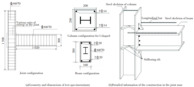
2 Experimental Studies 2.1 Specimens and Test SetupThe systems detailed in Table 1 consist of six beam-column joint specimens. The geometry and dimensions of the test specimens are shown in Fig. 1. All specimens were subjected to cyclic lateral loading. The dimensions of the SRUHSC column sections were 200 mm×200 mm, as depicted in Fig. 1. The main parameters considered in the study included ratio of axial compression ratio nt(0.25, 0.38 and 0.45), and volumetric ratio of stirrup ρv(0.8%, 1.2%).The compressive strength of concrete was 112 MPa, which was determined by compression tests on 10 cubic specimens with each side dimension of 150 mm. All the specimens have the same extent of longitudinal reinforcements and stirrup with a concrete cover of 20 mm. And, all the specimens are 1.02 m long and 1.5 m high. The material properties are listed in Tables 2 and 3 including the yield stress fy, ultimate stress fu values of the longitudinal steel bar and stirrup bar.
| Table 1 Test specimen matrix |
|
Figure 1 Details of test specimens |
| Table 2 Mechanical properties of steel |
| Table 3 Mechanical properties of structural steel |
2.2 Test Procedure and Instrumentation
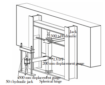
The test instrumentation is delineated in Fig. 2, which consists of two 300 kN hydraulic jacks applied at the beam ends to simulate the lateral load and a 2 000 kN hydraulic jack to simulate the constant axial load of column. The column was hinged at the ends to restrain the top and the bottom, while the beam is free to move.The constant axial load was applied to the column through the 2 000 kN hydraulic jack to simulate the weight of a few stories above the studied column. Then the simulated cyclic lateral load was applied by pulling and pushing vertically the beam.Two linear variable differential transformers (LVDT), two 200 mm strain gauges and two 500 mm strain gauges were used to measure the displacement at various locations on each specimen.
|
Figure 2 Test setup for all specimens |
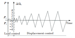
All specimens were loaded under load control before the specimen yielded and displacement-control after the specimen yielded. The number of cycles was then taken to lateral yielding displacement levels of Δy, 2Δy, 3Δy, 4Δy, etc. The loading was repeated only once at each control point before the specimen yielded and repeated two times at each control point to obtain the degraded curves of restoring force after the specimen yielded. The adopted loading history is shown in Fig. 3.
|
Figure 3 Loading history |
3 Description of Test Behavior
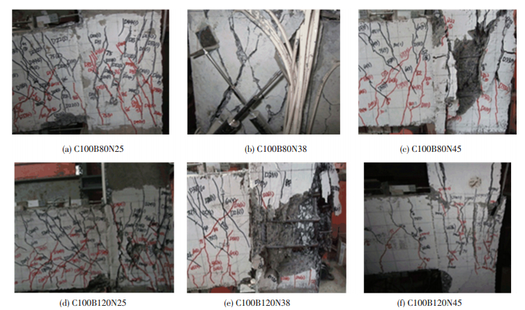
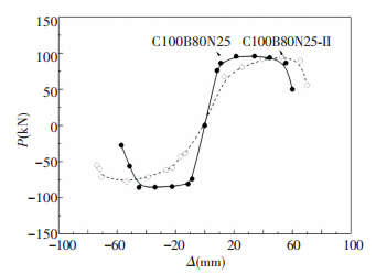
The failure modes and measured load versus displacement hysteresis loops of specimens are shown in Figs. 4 and 5, respectively.It can be seen that axial compression ratio as an important parameter has a significant impact on the failure modes of the specimens. As the axial compression ratio increases, the expansion of cracks is delayed and limited. However, when the axial compression ratio increases to 0.45, the failure modes of the specimens have transformed from shear failure to compression failure.
|
Figure 4 Crack patterns of specimens |

|
Figure 5 Hysteretic loops |
3.1 C100B80N25
For C100B80N25, cracking of the concrete at the end of the beam was first observed when the lateral force reaches positive 30 kN.The diagonal cracks in the joint were first observed at 1% story drift accompanied by beam longitudinal bars yielding. Two major diagonal cracks were identified, each emanating from a corner of the joint and extending diagonally to the exterior column surface. The concrete at the joint core began to crush at 5% story drift and the crushing concrete was gradually expanding with the increase of the displacement amplitude. Finally, the shear failure occurred at the joint core with plastic hinge formation.
3.2 C100B80N38Similarly, for C100B80N38, shear failure at the joint core occurred after significant joint yielding and extensive diagonal crack development as shown in Fig. 4(b). Contrary to C100B80N25, the formation of diagonal cracks at the joint core was delayed and the primary cracks were in a more prominent. Initial cracks formed at the top portion of the beam during drift ratio of 0.5% and propagated rapidly when drift ratio of 1.0% was attained, accompany by initial cracks at joint core. As the drift ratio increased, more cracks were found to propagate rapidly at the end of beam as well as joint core. The specimen began to deteriorate after a drift ratio of 3.0% and was declared shear failure when a drift ratio of 4.0% was attained.
3.3 C100B80N45It is substantially different from C100B80N25 and C100B80N38 that the failure mode of C100B80N45 is similar to little eccentric compression as shown in Fig. 4(c). The similarity among C100B80N25, C100B80N38 and C100B80N45 is that narrow diagonal cracks at the joint core have begun to appear at 1% story drift.However, the growth of diagonal cracks was more rapid and the joint diagonal cracks turned vertically above and below the joint, following direction of the column steel flange. This led to spalling of the concrete in the connection at 2% story drift and severe damage in the joint region by the end of the test.
In the case of C100B120N25, C100B120N38 and C100B120N45, the failure mode is mainly similar to C100B80N25, C100B80N38 and C100B80N45 as shown in Figs. 4(d), (e) and (f). It can be concluded that the increase of volumetric ratio of stirrup at the range in this paper has not caused apparently effect on the failure mode.
4 Discussions of Test Results 4.1 Effect of Axial Compression RatioThe current standards in China recommend the conversion coefficient of design axial compression ratio and test axial compression ratio as follows:
| $ {n_t} = \frac{{{N_k}}}{{{f_{ck}}{A_c} + {f_{ak}}{A_a}}} $ |
nt is the test axial compression ratio; Nk is the test axial compression load; fck is the characteristic value of concrete compressive strength; Ac is the section area of column; fak is the characteristic value of steel compressive strength; Aa is the section area of steel.
| $ {n_d} = \frac{{{N_d}}}{{{f_c}{A_c} + {f_a}{A_a}}} $ |
nd is the design axial compression ratio; Nd is the design of axial load; fc is the design value of concrete compressive strength; fa is the design value of steel compressive strength.
| $ {N_d} = {\gamma _G}{N_{GK}} + {\gamma _E}{N_{EK}} \approx 1.23{N_k} $ |
In accordance with GB50010 (2010)[15], the conversion coefficient of characteristic compressive strength and design compressive strength is as follows:
| $ \begin{array}{l} {f_c} = {f_{ck}}/{\gamma _c} = {f_{ck}}/1.4\\ {f_a} = {f_{ak}}/{\gamma _s} \end{array} $ |
γc is the material partial coefficients of concrete; γs is the material partial coefficients of steel. In this research program, conservative value is selected as follows: γc=γs[14]. Hence,
| $ {n_d} = \frac{{{N_d}}}{{\frac{{{f_{ck}}{A_c}}}{{{\gamma _c}}} + \frac{{{f_{ak}}{A_a}}}{{{\gamma _s}}}}}{\rm{ = }}\frac{{1.23 \times 1.4{N_k}}}{{{f_{ck}}{A_c} + {f_{ak}}{A_a}}} = \frac{{1.722{N_k}}}{{{f_{ck}}{A_c} + {f_{ak}}{A_a}}} $ |
The conversion coefficient is as follows:
| $ {n_d} = 1.722{n_t} $ |
To compare the ultimate deformation capacity of SUSHRC exterior joints, the inelastic deformation is quantified by displacement ductility μΔ. Based on the characteristic of hysteretic responses of SRUHSC exterior joints, the displacement ductility μΔ is defined as follows[16]:
| $ {u_{\mathit{\Delta }} } = \frac{{{{\mathit{\Delta }} _y}}}{{{{\mathit{\Delta }} _u}}} $ |
where Δμ and Δy are the ultimate and yielding displacement respectively. Δμ is defined as the post-spalling displacement where the residual lateral force has declined to 85% of Fmax, which depends on the final failure mode.
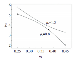
Fig. 6 shows the ductility coefficient of SRUHSC specimens with various axial compression ratios, indicating that encasing structural steel into SRUHSC frame is an effective method to enhance shear ductility. It can be readily seen that this result has two reasons. Firstly, the structural steel can improve the stiffness of the specimens. Secondly, the presence of structural steel also prevents immediate failure of the specimens and allows the capacity degenerating at slower rate in the post-peak region. In addition, it can be seen that the specimens with nt=0.25 exhibited a full ductile behavior, as well as an excellent capacity to sustain large inelastic cyclic displacement. The ductility value drops 57% when the axial compression ratio increases 80%, indicating a ngative effect of axial-load on the inelastic cyclic behavior of the joints.
|
Figure 6 μΔ-nt relationships of specimens |
4.1.2 Effect of axial compression ratio on stiffness and energy dissipation capacity
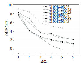
The looped cyclic stiffness kl is used to describe the stiffness degradation of the specimens as shown in Fig. 7, and the formula for calculating kl can be found as[17]:
|
Figure 7 Stiffness degradations |
| $ {k_l} = \sum\limits_{i = 1}^n {F_j^i} /\sum\limits_{i = 1}^n {{\mathit{\Delta }} _j^i} $ |
where Fji and Δji are the maximum values of the load and the corresponding displacement under the i cycle when the deformation is controlled as Δj=j×Δy and n is the number of cycles when the deformation is controlled as Δj=j×Δy.
As shown in Fig. 7, the axial compression ratio hasa significant effect on the stiffness degradation. It is indicated that the increase of axial compression ratio from 0.25 to 0.38 has improved the initial stiffness of the specimens and slowed the stiffness degradation.While the value of axial compression ratio is exceeding 0.38, the increase of axial compression ratio has caused initial stiffness decreasing and rapid degradation.
The phenomenon may be explained in two aspects. On the one hand, the stiffness of specimens mainly depends on the concrete strength at initial stage of loading. Since the increase of axial compression ratio can improve the bond stress and enhance the confinement of the stirrup, the effective compression strength of the concrete is improved. Hence, the increase of axial compression ratio from 0.25 to 0.38 caused initial stiffness of the specimens increasing. In addition, the curves of stiffness degradation of C100B80N38 is more gentle inclined compared to C100B80N25, indicating that lateral resistance behavior of SRUHSC exterior joints can be improved by raising the axial compression load at a certain range. On the other hand, a per-high axial compression ratio may cause a negative effect on the inelastic cyclic behavior of the specimens when the axial compression ratio increases to 0.45. Shear stress tends to increase to the failure stress while bending displacement has not yet to develop and brittle failure occurs.
The energy dissipation capacity is an important part to evaluate the seismic behavior of the structure. The energy dissipation is defined for a cycle i by the hatched area in Fig. 8, and mathematically by:

|
Figure 8 Schematic diagram of calculation of he |
| $ {E_i} = \int {P{\rm{d}}{\mathit{\Delta }} } $ |
Similarly, the effect of axial compression ratio on the energy dissipation is divided into two cases with the value of 0.38 as a transition point. It can be seen from Fig. 9 that the specimens are all in elastic stage before the number of cycles n=5 and the cumulative energy dissipation grows linearly. While as the increase of the cyclic number, the energy dissipation of C100B80N38 grows fastest with maximum energy dissipation of 20 kN·m. In contrast, C100B80N25 shows slower growth of energy dissipation, but presents higher maximum cumulative energy dissipation of 37.5 kN·m due to more sufficient inelastic behavior. However, the specimens with nt=0.45 exhibits poor energy dissipation capacity with the maximum cumulative energy dissipation of 11 kN·m.

|
Figure 9 Energy dissipation capacities of specimens |
4.1.3 Effect of axial compression ratio on joint shear strength
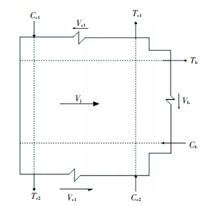
The horizontal joint shear force is estimated using the notation given in Fig. 10 as follows.
|
Figure 10 External actions and internal shears at exterior joint |
The equilibrium of the horizontal forces yields the following equilibrium equation based on the moment balance:
| $ {V_j} = {T_b} - {V_c} = \frac{{{M_b}}}{{{h_w}}} - \frac{{{M_b}}}{{H - {h_b}}} = \frac{{{M_b}}}{{{h_w}}}\left( {1 - \frac{{{h_w}}}{{H - {h_b}}}} \right) $ |
where Vj is the horizontal joint shear force; Tb is the tensile force resulting from the steel of the beam; and Vc is the horizontal column shear above the joint; Mb is the ultimate beam-end bending moment corresponding to the shear failure at the joint core. hw is the depth of the joint core region. hb is the width of the joint core region.
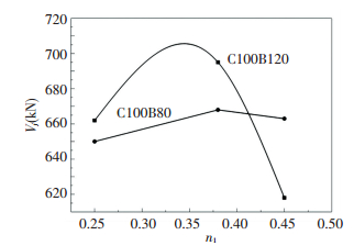
Fig. 11 shows the joint shear strength with various axial compression ratios. It can be seen that when the axial compression ratio increases from 0.25 to 0.38, the shear strength at the joint core area has increased. The reason for the phenomenon is explained that the axial compression load has caused enhancement of bond strength, leading to the reduction of applied shear force in the diagonal compressive strut[17-19].In addition, axial compression load also helped to increase the size of the diagonal compressive strut, enhancing the capacity of the diagonal compressive strut[20-22]. However, when the axial compression ratio increases from 0.38 to 0.45, the shear capacity declines slightly. That is because that when the axial compression ratio continues to increase, the oblique pressure of the concrete at joint core after hoops succumbing has increased rapidly to cause the collapse of concrete. Therefore, it can be seen that when the axial compression ratio is greater than 0.38, the axial-load has a negative effect on the seismic behavior of the joint.
|
Figure 11 Shear strength at joint core with various axial compression ratio |
4.1.4 Effect of axial compression ratio on joint shear deformation
C100B80N25 and C100B120N25 obtained the maximum diagonal compressive strain of 0.022 and 0.01respectively, as shown in Fig. 12. However, the maximum diagonal compressive strains of C100B80N38 and C100B120N38 during the test were 0.007 and 0.001, which are much smaller than the strains of the specimens with nt=0.25. It is indicated that axial compression load limited the shear deformation of the joint core. However, for C100B80N45 with crack patterns controlled by compression failure, the restriction is not obvious at the joint core.

|
Figure 12 Joint shear strength versus shear angle curves |
Fig. 13 shows the components of the horizontal displacement measured for the specimens at the peak of the selected loading cycles. They are expressed as a percentage of the story drift angle. According to Fig. 13(a), the contribution of beam rotation as the predominant component to the total drift is 54.8%, while the percentage of the story drift angle caused by joint shear is 39.6%. In the case of C100B80N38, the contribution of joint shear decreases to 33%, while the contribution of beam rotation and column flexure are 60% and 7%, respectively. It is indicated that the percentage of joint shear has reduced compared to C100B80N25, which is consistent with the results of shear angle.For C100B80N45, the contribution of beam rotation, joint shear distortion and column flexure were 4%, 24% and 72%, respectively. Apparently, the contribution of column flexure to the total drift was predominant due to high axial load.

|
Figure 13 Displacement decomposition results of specimens |
4.2 Effect of Volumetric Ratio of Stirrup on Behavior of Joints
The stirrup strain of the specimens is shown in Fig. 14. It can be seen that the stirrup at the joint core is in elastic stage before beam bend and the value of stirrup strain is 500 με. As the beam bending, the stirrup strain gradually increased. The research shows that the stirrup stress caused by hoop truss mechanism has decreased due to bonding degradation. And the stirrup stress which constraints the core concrete has increased. While the value of the load is close to the ultimate load, the stirrup strain increases rapidly to yield strain. Once the stirrup yield, the constraint to concrete at joint core has degenerated and the concrete inclined to crush.

|
Figure 14 Load strain curves of stirrup under different axial compression ratios |
In addition, the experiment results point to the influence of volumetric ratio of stirrup as an important parameter in controlling joint response. Fig. 14 shows that the stirrup strain of C100B80N25 increases rapidly and much higher than C100B80N38 and C100B80N45 while the load increases to ultimate load. It is indicated that the truss mechanism of stirrup can play a greater tensile potential when the axial compression is lower. It is shown in Fig. 6 that raising the ratio of stirrup can significantly improve the ductility of the SRUHSC exterior joints.From the test results, it can be seen that the limit test value of axial compression ratio is 0.45, and corresponding limit design value is 0.77 with the condition of μ≥3. For steel reinforced normal concrete specimens, JGJ-138-2001 recommends the minimal value of volumetric ratio of stirrup as 0.8%. From the experimental results of in this research program, the value seems not be acceptable to reach ductile behavior. For C100B120N45, the ductility coefficient is 3.28, with the value approximated to the value of 3.54 for C100B80N38. It can be concluded that the ductility of the specimens may be improved by raising volumetric ratio of stirrup at a certain range and the recommended minimum volumetric ratio is 1.2% under the test axial compression ratio less than or equal to 0.45.
4.3 Effect of Steel Ratio on Behavior of JointsYan C W[18]reported that the shape of steel can impact the ductility of the joint specimens, and the ┼ steel-shaped ones have higher ductility compared to the 工 steel-shaped specimens due to better confinement. And this paper is mainly to study the effect of steel ratio on the SRUHRC joints.
Fig. 15 shows the skeleton curves of the specimens with various steel ratio. It can be seen that the increase of steel ratio leads to an increase of the carrying capacity of the specimens due to the initial stiffness of specimens is improved and the ductility has not been increased significantly within the scope of this test.
|
Figure 15 Skeleton curves of specimens with different steel ratio |
5 Conclusions
1) Axial compression ratio significantly influences the failure mode of SRUHSC exterior joints, with essential change when the test axial compression ratio is equal to 0.45. It is evident that, the damage of the joint core area is serious for lower axial compression ratio with more damage taking place in the plastic hinge regions of the adjacent beams, while with most damage just taking place in the joint core area for the specimens with higher axial compression ratio.
2) Axial compression ratio has an impact on the seismic behavior of SRUHSC exterior joints including load-displacement curves, ductility, energy dissipation capacity, stiffness degradation, shear capacity, and shear deformation of the joint core through influencing to the transfer mechanism of the joint.
3) Axial compression ratio has an impact on the seismic behavior of exterior joint with beneficial aspect and detrimental aspect bounded by the value of 0.38. In the seismic design of SRUHSC specimens, the detrimental aspect should be taken into account when the axial compression ratio exceeding 0.38 (the design axial compression ratio exceeding 0.65). It is an effective way to ensure to behave ductilely by raising the volumetric ratio of stirrup.
4) The SRUHSC exterior joints are adequately confined when the volumetric ratio of stirrup is 1.2% related to the axial compression ratio is 0.45(the design axial compression ratio is 0.78).
The safe and economical design of SRUHSC in seismic zones depends on relating the required ductility to the confinement detailing and volumetric ratio of stirrup. When the SRUHSC specimens are subjected to a high axial compression ratio, a significant volumetric ratio of stirrup is necessary.
| [1] |
Pu X C, Wang Z J, Wang C, et al. Mechanical properties of super high-strength and high performance concrete. Journal of building Structure, 2002, 23(6): 49-55. ( 0) 0)
|
| [2] |
Mendis P. Plastic hinge lengths of normal and high-strength concrete in flexure. Advances in Structural Engineering, 2001, 10(1): 37-46. ( 0) 0)
|
| [3] |
JGJ 138. Technical Specification for Steel Reinforced Concrete Composite Structures. Beijing: Standards of the People Republic of China, 2016.
( 0) 0)
|
| [4] |
NZS 3101. Part 1Code of Practice for the Design of Concrete Structures. Wellington, New Zealand: Standards Association of New Zealand, 2006.
( 0) 0)
|
| [5] |
ACI 318. Building Code Requirements for Structural Concrete and Commentary. Farmington Hills, Mich: American Concrete Institute, 2005.
( 0) 0)
|
| [6] |
Lin C M, Restropo J I, Park R. Seismic behavior and design of reinforcement concrete interior beam-column joints. Bulletin of the New Zealand Society for Earthquake Engineering, 2002, 35(2): 108-128. ( 0) 0)
|
| [7] |
Xu Y, Jia L G, Wang L G, et al. Bearing capacity of side joint of steel reinforced hs concrete frame for shear load. Journal of Northeastern University, 2005, 26(2): 167-170. ( 0) 0)
|
| [8] |
Shin M, Lafave J M. Modeling of cyclic joint shear deformation contributions in RC beam-column connections to overall frame behavior. Structural Engineering and Mechanics, 2004, 18(5): 645-669. DOI:10.12989/sem.2004.18.5.645 ( 0) 0)
|
| [9] |
Tao M X, Fan J S, Nie J G. Seismic behavior of steel reinforced concrete column-steel truss beam hybrid joints. Engineering Structures, 2013, 56(3): 1557-1569. ( 0) 0)
|
| [10] |
Tao Z, Han L H, Zhuang J P. Axial loading behavior of CFRP strengthened concrete-filled steel tubular stub columns. Advances in Structural Engineering, 2007, 10(1): 37-46. DOI:10.1260/136943307780150814 ( 0) 0)
|
| [11] |
Zhu W Q, Jia J Q, Meng G. Experimental studies on axial load performance of high strength concrete short columns. ICE-Structures and Buildings, 2014, 167(9): 509-519. ( 0) 0)
|
| [12] |
Xue J Y, Zhao H T. Seismic behavior and construction method of steel reinforced concrete. World Earthquake Engineering, 2002, 18(2): 61-64. ( 0) 0)
|
| [13] |
Zhang X S, Li H T, Zhang T R. The effect of dog-bone style weakened flanges of shaped steel on SRC joint. Journal of Harbin Institute of Technology, 2009, 41(12): 110-114. ( 0) 0)
|
| [14] |
Chen Z P, Xu J J, Xue J Y. Seismic behavior and influence factor analysis on 3D side joints composed of steel reinforced concrete special-shaped columns and steel beams. Engineering Mechanics, 2015, 32(2): 105-113. ( 0) 0)
|
| [15] |
GB 50010. Code for Design of Concrete Structures. Beijing: Standards of the People Republic of China, 2010.
( 0) 0)
|
| [16] |
Liu W, Jia J Q, Li Y. Study on seismic performance of exterior steel reinforced ultra high strength concrete frame connection. Wuhan University Journal, 2014, 38(6): 1333-1337. ( 0) 0)
|
| [17] |
Fan G X, Song Y P, Wang L C. Experimental study on the seismic behavior of reinforced concrete beam-column joints under various strain rates. Journal of Reinforced Plastics Composites, 2014, 33(7): 601-618. DOI:10.1177/0731684413512706 ( 0) 0)
|
| [18] |
Yan C W. Study on Seismic Performance of Steel Reinforced Ultra High Strength Concrete Frame Connection. Dalian: Dalian University of Technology, 2009.
( 0) 0)
|
| [19] |
Parra-Momtesinos G, Wight J K. Modeling shear behavior of hybrid RCS beam-column connections. Journal of Structural Engineering, 2001, 127(1): 3-11. DOI:10.1061/(ASCE)0733-9445(2001)127:1(3) ( 0) 0)
|
| [20] |
Jia J Q, Jiang R. An experimental study on the seismic performance of steel reinforced super high-strength concrete columns. China Civil Engineering Journal, 2006, 39(8): 14-18. ( 0) 0)
|
| [21] |
Wang L C, Fang G X, Qin Q, et al. Experimental study on seismic behavior of reinforced concrete frame joints with consideration of strain rate effect. Journal of Building Structures, 2014, 35(2): 38-45. ( 0) 0)
|
| [22] |
Chen C C, Suswanto B, Lin Y J. Behavior and strength of steel reinforced concrete beam-column joints with single-side force inputs. Journal of Construction Steel Research, 2009, 6543: 1569-1581. ( 0) 0)
|
 2017, Vol. 24


