As a kind of position and speed sensor, the flux variable-reluctance resolver (FVR) which takes the real-time detection to angle position information of rotor accurately in servo control system has a good development prospect in aviation, space, automotive, industry and other fields[1].
The existing flux variable-reluctance resolver mainly includes radial type and axial type. For radial FVR, the excitation and signal windings are placed in the teeth of stator, and the rotor adopts a convex structure. However, the accuracy of radial FVR is restricted by the installation position of the winding and rotor[2]. The volume becomes larger when pole pairs increase. Different from radial FVR, the axial FVR is provided with rotor which is a sine function distributing along the axial direction[3-4]. The axial FVR could not simultaneously achieve absolute position detection and volume expansion[5-14].
To compensate for the shortcomings of existing FVR, this paper introduces a new coupling axial FVR with sine signal winding who possesses the characteristics of absolute position detection, high accuracy, and compact structure[15-19]. By studying the structure and principle, the impact of different factors on the measurement accuracy is analyzed. The optimized model of coupling axial FVR with sine signal winding can be got for wide application[20-23].
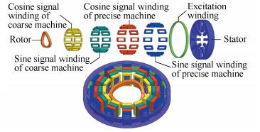
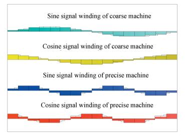
2 Structure DescriptionFig. 1 shows the components of the two pole pairs coupling axial FVR with sine signal winding which includes stator, rotor, sine signal winding of coarse machine, cosine signal winding of coarse machine, sine signal winding of precise machine, cosine signal winding of precise machine and excitation winding. Excitation winding is placed in the middle slot of stator along the circumferential direction. There is an equal gap between stator and rotor. In Fig. 2, the rotor which is composed of magnetic material can be divided into precision machine part and coarse machine part. Magnetic material of precise machine contains P peaks of wave and P troughs of wave, magnetic material of coarse machine contains one peak of wave and one trough of wave (P is pole pairs). All the signal windings are set on the stator teeth in Fig. 1.
|
Figure 1 The whole structure of the coupling axial flux variable-reluctance resolver |

|
Figure 2 The schematic diagram of combined rotor |
Fig. 3 shows the distribution of four-phase signal windings. Signal windings of coarse machine are arranged with the sine function whose frequency is equal to 1. And the frequency of sine function corresponding to signal windings of precise machine is P. Sine signal winding and cosine signal winding of the same machine have a difference of 90 electrical angle.
|
Figure 3 The number distribution of four-phase signal windings along the circumferential direction |
3 Operation Principle 3.1 Derivation of Coupling Area
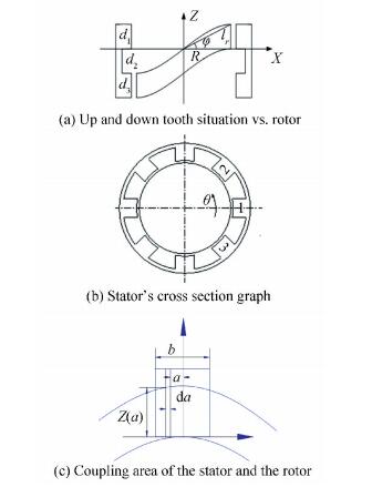
The sectional drawing of the resolver is shown as Fig. 4, assume d1=d2=d3=lr, where d1, d2, d3 are respectively the axial length of upper part, middle part, lower part and lr is the thickness of magnetic incline ring. Because the literature 4 has derived the coupling area of axial FVR, this paper does no longer elaborate in detail.
|
Figure 4 The relationship between stator and rotor |
The coupling area of same upper and lower teeth can be expressed as:
| $ \begin{array}{*{20}{c}} {{S_1} = {S_{{\rm{up}}}} + {S_{{\rm{down}}}} = R \cdot \tan \varphi \cdot \left( {{A_1}\sin b \cdot \sin 2\theta + } \right.}\\ {\left. {2{A_2}\sin \left( {\frac{b}{2}} \right) \cdot \sin \theta } \right),0 \le \theta \le 2{\rm{ \mathsf{ π} }}} \end{array} $ |
where R is average length of air gap, b is tooth width, θ is the angle of rotor, φ is the inclination angle of rotor, A1 is the ratio of the upper teeth height of the stator and the function amplitude of the precision machine of rotor, A2 is the ratio of the upper teeth height of the stator and the function amplitude of the coarse machine of rotor.
3.2 EMF Derivation of the Four-phase Signal Windings Under Different Pole PairsAccording to position relations of stator teeth and rotor in Fig. 5, the air-gap flux of the ith tooth can be expressed as:

|
Figure 5 The corresponding relation between the stator and rotor |
| $ \begin{array}{l} {\phi _i} = {\phi _{i1}} + {\phi _{ip}} = {N_1}{I_m}{\mathit{\Lambda }_{1i}} + {N_1}{I_m}{\mathit{\Lambda }_{Pi}} = \\ \;\;\;\;\;\;{N_1}{I_m}{{\mathit{\Lambda '}}_1} \cdot \sin \left[ {\theta + \left( {i - \frac{1}{2}} \right) \cdot \frac{{2{\rm{ \mathsf{ π} }}}}{{{Z_s}}}} \right] + {N_1}{I_m}{{\mathit{\Lambda '}}_P} \cdot \\ \;\;\;\;\;\;\sin P\left[ {\theta + \left( {i - \frac{1}{2}} \right)\frac{{2{\rm{ \mathsf{ π} }}}}{{{Z_s}}}} \right] \end{array} $ | (2) |
where, Λ1i is the air gap permeance of the ith teeth corresponding to coarse machine function of rotor (CMFOR), ΛPi is the air gap permeance of the ith teeth corresponding to precision machine function of rotor (PMFOR), Λ1′ is the air gap permeance amplitude of each teeth corresponding to CMFOR, ΛP′ is the air gap permeance amplitude of each teeth corresponding to PMFOR, Φi1 is the air-gap flux of the ith teeth under the action of CMFOR, Φip is the air-gap flux of the ith teeth under the action of PMFOR, N1 is the number of excitation windings, Im is excitation current, and Zs is the number of stator teeth.
The number of four-phase signal windings on each stator teeth can be expressed as:
| $ \left\{ \begin{array}{l} {N_{csi}} = {N_{cm}}\sin \left[ {\left( {i - 1} \right)\frac{{2{\rm{ \mathsf{ π} }}}}{{{Z_S}}} + \frac{{2{\rm{ \mathsf{ π} }}}}{{{Z_S}}} \cdot \frac{1}{2}} \right]\\ {N_{cci}} = {N_{cm}}\cos \left[ {\left( {i - 1} \right)\frac{{2{\rm{ \mathsf{ π} }}}}{{{Z_S}}} + \frac{{2{\rm{ \mathsf{ π} }}}}{{{Z_S}}} \cdot \frac{1}{2}} \right] \end{array} \right. $ |
| $ \left\{ \begin{array}{l} {N_{jsi}} = {N_{jm}}\sin \left[ {\left( {i - 1} \right)\frac{{2{\rm{ \mathsf{ π} }}P}}{{{Z_S}}} + \frac{{2P{\rm{ \mathsf{ π} }}}}{{{Z_S}}} \cdot \frac{1}{2}} \right]\\ {N_{jci}} = {N_{jm}}\cos \left[ {\left( {i - 1} \right)\frac{{2{\rm{ \mathsf{ π} }}P}}{{{Z_S}}} + \frac{{2P{\rm{ \mathsf{ π} }}}}{{{Z_S}}} \cdot \frac{1}{2}} \right] \end{array} \right. $ |
where, Ncsi is the number of sine signal windings of coarse machine (SWOCM) on the ith stator tooth, Ncci is the number of cosine SWOCM on the ith stator tooth, Njsi is the number of sine signal windings of precision machine (SWOPM) on the ith stator tooth, Njci is the number of cosine SWOPM on the ith stator tooth, Ncm is the amplitude number of SWOCM, and Njm is the amplitude number of SWOPM.
The rotor function is decomposed into the sine function of coarse machine and the sine function of precision machine. The flux linkage of four-phase signal windings can be shown as follow:
| $ \left\{ \begin{array}{l} {\psi _{cs}} = \sum\limits_{i = 1}^{{Z_S}} {{N_{cm}}\sin \left[ {\left( {i - 1} \right)\frac{{2{\rm{ \mathsf{ π} }}}}{{{Z_S}}} + \frac{{2{\rm{ \mathsf{ π} }}}}{{{Z_S}}} \cdot \frac{1}{2}} \right]\left\{ {{{\phi '}_1}\sin \left[ {\theta + } \right.} \right.} \\ \;\;\;\;\;\;\;\;\;\left. {\left. {\left( {i - \frac{1}{2}} \right) \cdot \frac{{2{\rm{ \mathsf{ π} }}}}{{{Z_s}}}} \right] + {{\phi '}_P}\sin P\left[ {\theta + \left( {i - \frac{1}{2}} \right)\frac{{2{\rm{ \mathsf{ π} }}}}{{{Z_s}}}} \right]} \right\}\\ {\psi _{cc}} = \sum\limits_{i = 1}^{{Z_S}} {{N_{cm}}\cos \left[ {\left( {i - 1} \right)\frac{{2{\rm{ \mathsf{ π} }}}}{{{Z_S}}} + \frac{{2{\rm{ \mathsf{ π} }}}}{{{Z_S}}} \cdot \frac{1}{2}} \right]\left\{ {{{\phi '}_1}\sin \left[ {\theta + } \right.} \right.} \\ \;\;\;\;\;\;\;\;\;\left. {\left. {\left( {i - \frac{1}{2}} \right) \cdot \frac{{2{\rm{ \mathsf{ π} }}}}{{{Z_s}}}} \right] + {{\phi '}_P}\sin P\left[ {\theta + \left( {i - \frac{1}{2}} \right)\frac{{2{\rm{ \mathsf{ π} }}}}{{{Z_s}}}} \right]} \right\} \end{array} \right. $ | (5) |
| $ \left\{ \begin{array}{l} {\psi _{js}} = \sum\limits_{i = 1}^{{Z_S}} {{N_{jm}}\sin \left[ {\left( {i - 1} \right)\frac{{2{\rm{ \mathsf{ π} }}P}}{{{Z_S}}} + \frac{{2P{\rm{ \mathsf{ π} }}}}{{{Z_S}}} \cdot \frac{1}{2}} \right]\left\{ {{{\phi '}_1}\sin \left[ {\theta + } \right.} \right.} \\ \;\;\;\;\;\;\;\;\;\left. {\left. {\left( {i - \frac{1}{2}} \right) \cdot \frac{{2{\rm{ \mathsf{ π} }}}}{{{Z_s}}}} \right] + {{\phi '}_P}\sin P\left[ {\theta + \left( {i - \frac{1}{2}} \right)\frac{{2{\rm{ \mathsf{ π} }}}}{{{Z_s}}}} \right]} \right\}\\ {\psi _{jc}} = \sum\limits_{i = 1}^{{Z_S}} {{N_{jm}}\cos \left[ {\left( {i - 1} \right)\frac{{2{\rm{ \mathsf{ π} }}P}}{{{Z_S}}} + \frac{{2P{\rm{ \mathsf{ π} }}}}{{{Z_S}}} \cdot \frac{1}{2}} \right]\left\{ {{{\phi '}_1}\sin \left[ {\theta + } \right.} \right.} \\ \;\;\;\;\;\;\;\;\;\left. {\left. {\left( {i - \frac{1}{2}} \right) \cdot \frac{{2{\rm{ \mathsf{ π} }}}}{{{Z_s}}}} \right] + {{\phi '}_P}\sin P\left[ {\theta + \left( {i - \frac{1}{2}} \right)\frac{{2{\rm{ \mathsf{ π} }}}}{{{Z_s}}}} \right]} \right\} \end{array} \right. $ |
where, ψcs is the flux linkage of sine SWOCM, ψcc is the flux linkage of cosine SWOCM, ψjs is the flux linkage of sine SWOPM, ψjc is the flux linkage of cosine SWOPM, Φ1′ is the air-gap flux amplitude under the action of CMFOR, and ΦP′ is the air-gap flux amplitude under the action of PMFOR.
Further simplification can be obtained,
| $ \left\{ \begin{array}{l} {\psi _{cs}} = \sum\limits_{i = 1}^{{N_S}} {{N_{cm}}{{\phi '}_1} \cdot \frac{1}{2}\cos \theta } = \frac{1}{2} \cdot {Z_s}{N_{cm}}{{\phi '}_1} \cdot \cos \theta \\ {\psi _{cc}} = \sum\limits_{i = 1}^{{N_S}} {{N_{cm}}{{\phi '}_1} \cdot \frac{1}{2}\sin \theta } = \frac{1}{2} \cdot {Z_s}{N_{cm}}{{\phi '}_1} \cdot \sin \theta \\ {\psi _{js}} = \sum\limits_{i = 1}^{{N_S}} {{N_{jm}}{{\phi '}_P} \cdot \frac{1}{2}\cos P\theta } = \frac{1}{2} \cdot {Z_s}{N_{jm}}{{\phi '}_P} \cdot \cos P\theta \\ {\psi _{jc}} = \sum\limits_{i = 1}^{{N_S}} {{N_{jm}}{{\phi '}_P} \cdot \frac{1}{2}\sin P\theta } = \frac{1}{2} \cdot {Z_s}{N_{jm}}{{\phi '}_P} \cdot \sin P\theta \end{array} \right. $ |
Electromotive force of four-phase signal windings can be expressed as:
| $ \left\{ \begin{array}{l} {e_{cs}} = - \frac{{{\rm{d}}{\psi _{cs}}}}{{{\rm{d}}t}} = - \frac{1}{2} \cdot {Z_s}{N_{cm}} \cdot \cos \theta \frac{{{\rm{d}}{{\phi '}_1}}}{{{\rm{d}}t}} = - {e_{m1}}\cos \theta \\ {e_{cc}} = - \frac{{{\rm{d}}{\psi _{cc}}}}{{{\rm{d}}t}} = - \frac{1}{2} \cdot {Z_s}{N_{cm}} \cdot \sin \theta \frac{{{\rm{d}}{{\phi '}_1}}}{{{\rm{d}}t}} = - {e_{m1}}\sin \theta \end{array} \right. $ |
| $ \left\{ \begin{array}{l} {e_{js}} = - \frac{{{\rm{d}}{\psi _{js}}}}{{{\rm{d}}t}} = - \frac{1}{2} \cdot {Z_s}{N_{jm}} \cdot \cos P\theta \frac{{{\rm{d}}{{\phi '}_P}}}{{{\rm{d}}t}} = - {e_{mP}}\cos P\theta \\ {e_{jc}} = - \frac{{{\rm{d}}{\psi _{jc}}}}{{{\rm{d}}t}} = - \frac{1}{2} \cdot {Z_s}{N_{jm}} \cdot \sin P\theta \frac{{{\rm{d}}{{\phi '}_P}}}{{{\rm{d}}t}} = - {e_{mP}}\sin P\theta \end{array} \right. $ |
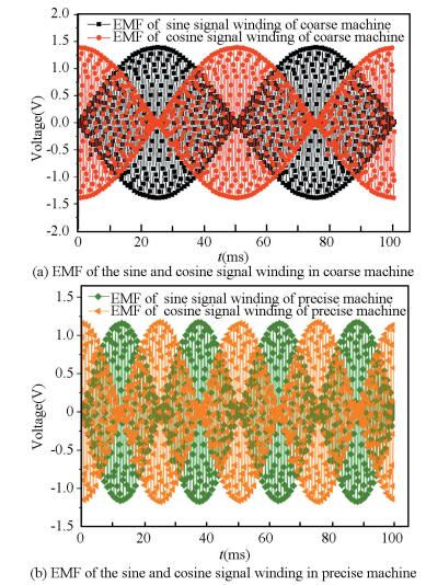
The coupling axial flux variable-reluctance resolver (FVR) with sine signal winding whose precise machine pole pairs are 2 is simulated by the finite element software. Fig. 6 shows the EMF waveform of the four-phase signal windings. The tendency of waveform is consistent with EMF derivation of the four-phase signal windings.
|
Figure 6 The EMF waveform of the four-phase signal windings |
4 Harmonic Analysis of Signal Winding EMF of Precision Machine 4.1 Harmonic Derivation of the Precise Signal Windings EMF
Make ZS=QP(Q is a natural number), EMF of sine signal winding of precision machine (SWOPM) can be expressed as:
| $ \begin{array}{l} {E_{js}} = {{E'}_{js}} + {{E''}_{js}} = \\ \;\;\;\;\; - {\rm{j}}\omega {I_m}{N_1}\sum\limits_{i = 1}^{{Z_s}} {{N_{jsi}}\left( {{\mathit{\Lambda }_{1i}} + {\mathit{\Lambda }_{Pi}}} \right)} = \\ \;\;\;\;\; - {\rm{j}}\omega {I_m}{N_1}\sum\limits_{i = 1}^{{Z_s}} {{N_{jm}}\sin \left[ {\left( {i - 1} \right)\frac{{2{\rm{ \mathsf{ π} }}P}}{{{Z_S}}} + \frac{{2P{\rm{ \mathsf{ π} }}}}{{{Z_S}}} \cdot } \right.} \\ \;\;\;\;\;\left. {\frac{1}{2}} \right]\left\{ {{\mathit{\Lambda }_{10}} + \sum\limits_{\gamma = 1}^\infty {{\mathit{\Lambda }_{1\gamma }}\cos \left[ {\gamma \theta + \left( {i - \frac{1}{2}} \right)\frac{{2\gamma {\rm{ \mathsf{ π} }}}}{{{Z_S}}}} \right]} + } \right.\\ \;\;\;\;\;\left. {{\mathit{\Lambda }_{P0}} + \sum\limits_{\gamma = 1}^\infty {{\mathit{\Lambda }_{P\gamma }}\cos \left[ {\gamma P\theta + \left( {i - \frac{1}{2}} \right)\frac{{2\gamma P{\rm{ \mathsf{ π} }}}}{{{Z_S}}}} \right]} } \right\} \end{array} $ |
where, Ejs′ is EMF of sine SWOPM which is lonely effected by PMFOR, Ejs″ is EMF of sine SWOPM which is lonely effected by CMFOR, Λ10 is the constant component of air gap permeance corresponding to CMFOR, ΛP0 is the constant component of air gap permeance corresponding to PMFOR, Λ1γ is the γth harmonic component of air gap permeance corresponding to CMFOR, and ΛPγ is the γth harmonic component of air gap permeance corresponding to PMFOR.
The constant component of sine signal winding EMF of precision machine Ejs0 is
| $ \begin{array}{l} {E_{js0}} = - {\rm{j}}\omega {I_m}{N_1}\left( {{\mathit{\Lambda }_{10}} + {\mathit{\Lambda }_{P0}}} \right)\sum\limits_{i = 1}^{{Z_s}} {{N_{jsi}}} = \\ \;\;\;\;\;\;\; - {\rm{j}}\omega {I_m}{N_1}\left( {{\mathit{\Lambda }_{10}} + {\mathit{\Lambda }_{P0}}} \right)\sum\limits_{i = 1}^{{Z_s}} {{N_{jm}}\sin \left[ {\left( {i - 1} \right)\frac{{2{\rm{ \mathsf{ π} }}P}}{{{Z_S}}} + } \right.} \\ \;\;\;\;\;\;\;\left. {\frac{{2P{\rm{ \mathsf{ π} }}}}{{{Z_S}}} \cdot \frac{1}{2}} \right] = 0 \end{array} $ |
The fundamental component of sine signal winding EMF of precision machine lonely effected by precision machine function of rotor Ejs1′ is:
| $ \begin{array}{l} {{E'}_{js1}} = - {\rm{j}}\omega {I_m}{N_1}\sum\limits_{i = 1}^{{Z_s}} {{N_{jsi}}{\mathit{\Lambda }_{P1}}\cos \left[ {p\theta + \left( {i - \frac{1}{2}} \right)\frac{{2p{\rm{ \mathsf{ π} }}}}{{{Z_S}}}} \right]} = \\ \;\;\;\;\;\; - {\rm{j}}\omega {I_m}{N_1} \cdot {Z_s}{N_{jm}}{\mathit{\Lambda }_{P1}} \cdot \frac{1}{2}\sin P\theta \end{array} $ |
The high-order harmonic component of sine signal winding EMF of precision machine lonely effected by precision machine function of rotor Ejsγ′ is:
| $ \begin{array}{l} {{E'}_{js\gamma }} = - {\rm{j}}\omega {I_m}{N_1}\sum\limits_{i = 1}^{{Z_s}} {{N_{jsi}}{\mathit{\Lambda }_{P\gamma }}\cos \left[ {\gamma p\theta + \left( {i - \frac{1}{2}} \right)\frac{{2\gamma p{\rm{ \mathsf{ π} }}}}{{{Z_S}}}} \right]} = \\ \;\;\;\;\;\;\;\;\; - {\rm{j}}\omega {I_m}{N_1}\sum\limits_{i = 1}^{{Z_s}} {{N_{jsi}}{\mathit{\Lambda }_{P\gamma }}\left\{ {\frac{1}{2}\cos \left[ {\left( {1 + \gamma } \right)\left( {i - 1} \right) \cdot } \right.} \right.} \\ \;\;\;\;\;\;\;\;\;\left. {\frac{{2p{\rm{ \mathsf{ π} }}}}{{{Z_S}}}} \right]\cos \left[ { - \frac{{\rm{ \mathsf{ π} }}}{2} + \gamma p\theta + \frac{{\left( {1 + \gamma } \right)p{\rm{ \mathsf{ π} }}}}{{{Z_S}}}} \right] - \\ \;\;\;\;\;\;\;\;\;\frac{1}{2}\sin \left[ {\left( {1 + \gamma } \right)\left( {i - 1} \right)\frac{{2p{\rm{ \mathsf{ π} }}}}{{{Z_S}}}} \right]\sin \left[ { - \frac{{\rm{ \mathsf{ π} }}}{2} + \gamma p\theta + } \right.\\ \;\;\;\;\;\;\;\;\;\left. {\frac{{\left( {1 + \gamma } \right)p{\rm{ \mathsf{ π} }}}}{{{Z_S}}}} \right] - \frac{1}{2}\cos \left[ {\left( {1 - \gamma } \right)\left( {i - 1} \right)\frac{{2p{\rm{ \mathsf{ π} }}}}{{{Z_S}}}} \right]\cos \left[ {\frac{{\rm{ \mathsf{ π} }}}{2} - } \right.\\ \;\;\;\;\;\;\;\;\;\left. {\gamma p\theta + \frac{{\left( {1 - \gamma } \right)p{\rm{ \mathsf{ π} }}}}{{{Z_S}}}} \right] + \frac{1}{2}\sin \left[ {\left( {1 - \gamma } \right)\left( {i - } \right.} \right.\\ \;\;\;\;\;\;\;\;\;\left. {\left. {\left. 1 \right)\frac{{2p{\rm{ \mathsf{ π} }}}}{{{Z_S}}}} \right]\sin \left[ {\frac{{\rm{ \mathsf{ π} }}}{2} - \gamma p\theta + \frac{{\left( {1 - \gamma } \right)p{\rm{ \mathsf{ π} }}}}{{{Z_S}}}} \right]} \right\} \end{array} $ | (1) |
In Eq. (1),
| $ \begin{array}{l} \sum\limits_{i = 1}^{{Z_s}} {\sin \left[ {\left( {1 + \gamma } \right)\left( {i - 1} \right)\frac{{2p{\rm{ \mathsf{ π} }}}}{{{Z_S}}}} \right]} = \\ \;\;\;\;\frac{{\sin \left[ {\left( {1 + \gamma } \right)\left( {{Z_s} - 1} \right)\frac{{p{\rm{ \mathsf{ π} }}}}{{{Z_S}}}} \right]\sin \left[ {\left( {1 + \gamma } \right)p{\rm{ \mathsf{ π} }}} \right]}}{{\sin \left[ {\left( {1 + \gamma } \right)\frac{{p{\rm{ \mathsf{ π} }}}}{{{Z_S}}}} \right]}} \end{array} $ | (2) |
| $ \begin{array}{l} \sum\limits_{i = 1}^{{Z_s}} {\cos \left[ {\left( {1 + \gamma } \right)\left( {i - 1} \right)\frac{{2p{\rm{ \mathsf{ π} }}}}{{{Z_S}}}} \right]} = \\ \;\;\;\;\frac{{\cos \left[ {\left( {1 + \gamma } \right)\left( {{Z_s} - 1} \right)\frac{{p{\rm{ \mathsf{ π} }}}}{{{Z_S}}}} \right]\sin \left[ {\left( {1 + \gamma } \right)p{\rm{ \mathsf{ π} }}} \right]}}{{\sin \left[ {\left( {1 + \gamma } \right)\frac{{p{\rm{ \mathsf{ π} }}}}{{{Z_S}}}} \right]}} \end{array} $ | (3) |
The Eqs. (2) and (3) can be simplified as:
| $ \left\{ \begin{array}{l} \sum\limits_{i = 1}^{{Z_s}} {\cos \left[ {\left( {1 + \gamma } \right)\left( {i - 1} \right)\frac{{2p{\rm{ \mathsf{ π} }}}}{{{Z_S}}}} \right]} = 0,\\ \;\;\;\;\;\;\;\;\left( {1 + \gamma } \right)\frac{p}{{{Z_S}}} \ne 1,2,3 \cdots \cdots \\ \sum\limits_{i = 1}^{{Z_s}} {\cos \left[ {\left( {1 - \gamma } \right)\left( {i - 1} \right)\frac{{2p{\rm{ \mathsf{ π} }}}}{{{Z_S}}}} \right]} = {Z_s},\\ \;\;\;\;\;\;\;\;\left( {1 + \gamma } \right)\frac{p}{{{Z_S}}} \ne 1,2,3 \cdots \cdots \end{array} \right. $ |
| $ \sum\limits_{i = 1}^{{Z_s}} {\sin \left[ {\left( {1 - \gamma } \right)\left( {i - 1} \right)\frac{{2p{\rm{ \mathsf{ π} }}}}{{{Z_S}}}} \right]} = 0 $ |
The Eq.(1) can be expressed as:
| $ {{E'}_{js\gamma }} = \left\{ \begin{array}{l} - {\rm{j}}\omega {I_m}{N_1}\sum\limits_{i = 1}^{{Z_s}} {{N_{jm}}{\mathit{\Lambda }_{P\gamma }}\left\{ {\frac{1}{2}{Z_s}\cos \left[ {\gamma p\theta + } \right.} \right.} \\ \;\;\;\;\left. {\left. {\frac{{\left( {1 + \gamma } \right)p{\rm{ \mathsf{ π} }}}}{{{Z_S}}}} \right]} \right\},\left( {1 + \gamma } \right)\frac{p}{{{Z_S}}} = 1,2,3 \cdots \cdots \\ - {\rm{j}}\omega {I_m}{N_1}\sum\limits_{i = 1}^{{Z_s}} {{N_{jm}}{\mathit{\Lambda }_{P\gamma }}\left\{ {\frac{1}{2}{Z_s}\cos \left[ {\gamma p\theta + } \right.} \right.} \\ \;\;\;\;\left. {\left. {\frac{{\left( {\gamma - 1} \right)p{\rm{ \mathsf{ π} }}}}{{{Z_S}}}} \right]} \right\},\frac{{\left( {\gamma - 1} \right)p}}{{{Z_S}}} = 1,2,3 \cdots \cdots \\ 0,\;\;{\rm{otherwise}} \end{array} \right. $ |
The fundamental component of sine signal winding EMF of precision machine lonely effected by coarse machine function of rotor Ejs1″ is:
| $ {{E''}_{js1}} = 0 $ |
The high-order harmonic component of sine signal winding EMF of precision machine lonely effected by coarse machine function of rotor Ejsγ″ is
| $ {{E''}_{js\gamma }} = \left\{ \begin{array}{l} - {\rm{j}}\omega {I_m}{N_1}{N_{jm}}{\mathit{\Lambda }_{1\gamma }} \cdot \frac{1}{2} \cdot {Z_S}\cos \left[ { - \frac{{\rm{ \mathsf{ π} }}}{2} + \gamma \theta + } \right.\\ \;\;\;\;\;\left. {\frac{{\left( {P + \gamma } \right){\rm{ \mathsf{ π} }}}}{{{Z_S}}}} \right],\;\;\;\;\;\;\;\;\frac{{\left( {P + \gamma } \right)}}{{{Z_S}}} = 1,2,3 \cdots \cdots \\ - {\rm{j}}\omega {I_m}{N_1}{N_{jm}}{\mathit{\Lambda }_{1\gamma }} \cdot \frac{1}{2} \cdot {Z_S}\cos \left[ { - \frac{{\rm{ \mathsf{ π} }}}{2} + \gamma \theta + } \right.\\ \;\;\;\;\;\left. {\frac{{\left( {\gamma - P} \right){\rm{ \mathsf{ π} }}}}{{{Z_S}}}} \right],\;\;\;\;\;\;\;\;\frac{{\left( {\gamma - P} \right)}}{{{Z_S}}} = 1,2,3 \cdots \cdots \\ 0,\;\;\;\;\;\;\;\;\;\;\;\;\;\;\;\;\;\;\;\;\;\;\;\;\;\;\;{\rm{otherwise}} \end{array} \right. $ |
The fundamental component of cosine signal winding EMF of precision machine lonely effected by precision machine function of rotor Ejc1′ is
| $ {{E'}_{jc1}} = - {\rm{j}}\omega {I_m}{N_1} \cdot {Z_S}{N_{jm}}{\mathit{\Lambda }_{js1}} \cdot \frac{1}{2}\cos P\theta $ |
The high-order harmonic component of sine signal winding EMF of precision machine lonely effected by coarse machine function of rotor Ejcγ′ is
| $ {{E'}_{js\gamma }} = \left\{ \begin{array}{l} - {\rm{j}}\omega {I_m}{N_1}\sum\limits_{i = 1}^{{Z_s}} {{N_{jm}}{\mathit{\Lambda }_{P\gamma }}\left\{ {\frac{1}{2}{Z_s}\cos \left[ {\gamma p\theta + } \right.} \right.} \\ \;\;\;\;\left. {\left. {\frac{{\left( {1 + \gamma } \right)p{\rm{ \mathsf{ π} }}}}{{{Z_S}}}} \right]} \right\},\left( {1 + \gamma } \right)\frac{p}{{{Z_S}}} = 1,2,3 \cdots \cdots \\ - {\rm{j}}\omega {I_m}{N_1}\sum\limits_{i = 1}^{{Z_s}} {{N_{jm}}{\mathit{\Lambda }_{P\gamma }}\left\{ {\frac{1}{2}{Z_s}\cos \left[ {\gamma p\theta + } \right.} \right.} \\ \;\;\;\;\left. {\left. {\frac{{\left( {\gamma - 1} \right)p{\rm{ \mathsf{ π} }}}}{{{Z_S}}}} \right]} \right\},\frac{{\left( {\gamma - 1} \right)p}}{{{Z_S}}} = 1,2,3\\ 0,\;\;\;\;\;\;\;\;\;\;\;\;\;\;\;\;\;\;\;\;\;\;\;\;\;\;\;{\rm{otherwise}} \end{array} \right. $ |
The fundamental component of cosine signal winding EMF of precision machine lonely effected by coarse machine function of rotor Ejc1″ is
| $ {{E''}_{jc1}} = 0 $ |
The high-order harmonic component of sine signal winding EMF of precision machine lonely effected by coarse machine function of rotor Ejcγ″ is
| $ {{E''}_{jc\gamma }} = \left\{ \begin{array}{l} - {\rm{j}}\omega {I_m}{N_1}{N_{jm}}{\mathit{\Lambda }_{1\gamma }} \cdot \frac{1}{2} \cdot {Z_S}\cos \left[ {\gamma \theta + \frac{{\left( {P + \gamma } \right){\rm{ \mathsf{ π} }}}}{{{Z_S}}}} \right],\\ \;\;\;\;\;\frac{{\left( {P + \gamma } \right)}}{{{Z_S}}} = 1,2,3 \cdots \cdots \\ - {\rm{j}}\omega {I_m}{N_1}{N_{jm}}{\mathit{\Lambda }_{1\gamma }} \cdot \frac{1}{2} \cdot {Z_S}\cos \left[ {\gamma \theta + \frac{{\left( {\gamma - P} \right){\rm{ \mathsf{ π} }}}}{{{Z_S}}}} \right],\\ \;\;\;\;\;\frac{{\left( {\gamma - P} \right)}}{{{Z_S}}} = 1,2,3 \cdots \cdots \\ 0,\;\;\;\;\;\;\;\;\;\;\;\;\;\;\;\;\;\;\;\;\;\;\;\;\;\;\;{\rm{otherwise}} \end{array} \right. $ |
It can be seen from the above derivation, coarse machine function of rotor could bring about MZS±P order harmonic of sine signal winding EMF of precision machine. And precision machine function of rotor could produce (MZS±P)/P order harmonic of sine signal winding EMF of precision machine.
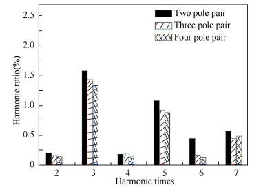
4.2 Harmonic Analysis on EMF of Precise Signal WindingsIn the case of invariable stator diameter, invariable rotor diameter, invariable axial length, invariable alveolar ratio and Zs=4P, the models of coupling axial FVR with sine signal winding are created when pole pairs of precise machine are respectively 2, 3 and 4. According to simulation of EMF and Fourier decomposition of EMF envelope, different order harmonic ratios are obtained. The results are shown in Fig. 7. Ratio of odd harmonics is higher than ratio of even harmonics in the three models. The sixth harmonic is slightly larger than other even harmonics when pole pairs of precise machine are 2. With the increase of pole pairs, the total harmonic ratio reduces. Above all, results of harmonic analysis are in close agreement with derived results.
|
Figure 7 The harmonic ratios of EMF under different pole pairs of precise machine |
5 The Error Experiment of Two Channels Coupling Axial FVR Prototype
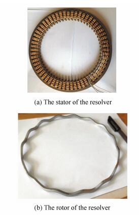
According to the principle above, an experimental prototype is designed, which has 1 pair of coarse channel, and 15 pairs of pole of fine channel co-magnetic circuit. This method of design can decouple the EMF signals of two channels within the scope of the given accuracy. External excitation voltage is 7 V. And excitation voltage frequency is 10 kHz. The stator and rotor photos is shown in Fig. 8.
|
Figure 8 The two channels coarse-exact coupling FVR |
At first, the input impedance and the output impedance of the co-excitation coarse and fine coupling axial reluctance rotary transformer are calculated by using the short circuit test and the open circuit test of the traditional transformer.
Input resistance: 1.5 ohm series resistance, the excitation winding is 6.9 ohm, the sine signal winding is 11.3 ohm and the cosine signal winding is 11.2 ohm.
Input impedance: Series resistance voltage, 89 mV; Power input voltage, 11.5 V;
| $ Z = \frac{{\left| U \right|}}{{\left| I \right|}} = \frac{{11.5}}{{0.089/1.5}} = 193.82\Omega $ |
| $ \begin{array}{l} X = \sqrt {{{\left| Z \right|}^2} - {R^2}} = \sqrt {{{193.82}^2} - {{\left( {1.5 + 6.9} \right)}^2}} = \\ \;\;\;\;\;\;\;193.638\Omega \end{array} $ |
Output impedance:Series resistance voltage, 85.4 mV; Power output voltage, 11.5 V;
| $ Z = \frac{{11.5}}{{0.0854/1.5}} = 201.99\Omega $ |
| $ X = \sqrt {{{201.99}^2} - {{\left( {1.5 + 11.3} \right)}^2}} = 201.58\Omega $ |
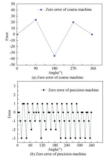
Second, the measured envelope curve of the two phases output voltage of precision machine is compared with the envelope curve under ideal condition, and the zero error can be obtained as shown in Fig. 9. From the error analysis, we can see that the zero error of the precision machine is about ±2′. And the zero error of the coarse machine is about ±30′.The results of the zero error basically meet the testing requirements of The coupling axial flux variable-reluctance resolver (FVR).
|
Figure 9 The two channels coarse-exact coupling FVR |
6 Conclusions
1) This paper brings forward a new coupling axial flux variable-reluctance resolver (FVR) with sine signal winding. And the whole structure is introduced in detail.
2) By the EMF derivation and simulation of the four-phase signal windings, theoretical correctness of this new coupling axial FVR with sine signal winding is verified.
3) The EMF harmonic of the precise signal windings is deduced. The results indicate coarse machine function of rotor (CMFOR) can cause MZS±P order EMF harmonic of precise signal winding. At the same time, precise machine function of rotor (PMFOR) can cause (MZS±P)/P order EMF harmonic of precise signal winding.
4) The models of coupling axial FVR with sine signal winding whose pole pairs of precise machine are respectively 2, 3, 4 are analyzed by the finite element method. The simulation results are consistent with the derivation results of EMF harmonic of precise signal windings.
5) The precision of the prototype is verified by experimental measurements, which proves the feasibility of this kind of coupling axial flux variable-reluctance resolver (FVR) in practical engineering.
| [1] |
Zeng Tao, Lu Zheng, Ding Zegang, et al. SAR doppler ambiguity resolver based on entropy minimization. IEEE Transactions on Geoscience and Remote Sensing, 2013, 51(8): 4405-4416. DOI:10.1109/TGRS.2013.2240305 ( 1) 1)
|
| [2] |
Figueiredo J. Resolver models for manufacturing. IEEE Transactions on Industrial Electronics, 2011, 58(8): 3693-3700. DOI:10.1109/TIE.2010.2081950 ( 1) 1)
|
| [3] |
Cui Shuimei, Hao Ge. Stator structure design and analysis of variable reluctance resolver for hybrid-vehicle motor drive. Proceedings of the 2012 IEEE 7th International Power Electronics and Motion Control Conference(IPEMC). Piscataway: IEEE, 2012. 2587-2592. DOI: 10.1109/IPEMC.2012.6259267.
( 1) 1)
|
| [4] |
Shang Jing, Wang Hao, Wang Weiqiang. The analysis of multipole axial flux reluctance resolver with sinusoidal rotor. Proceedings of the 2012 7th International Power Electronics and Motion Control Conference (IPEMC). Piscataway: IEEE, 2012, 2: 1206-1209. DOI: 10.1109/IPEMC.2012.6259007.
( 1) 1)
|
| [5] |
Kim K-C. Analysis on the charateristics of variable reluctance resolver considering uneven magnetic fields. IEEE Transactions on Magnetics, 2013, 49(7): 3858-3861. DOI:10.1109/TMAG.2013.2246549 ( 1) 1)
|
| [6] |
Bellini A, Bifaretti S. A digital filter for speed noise reduction in drives using an electromagnetic resolver. Mathematics and Computers in Simulation, 2006, 71(4-6): 476-486. DOI:10.1016/j.matcom.2006.02.007 ( 1) 1)
|
| [7] |
Sun L Z, Zou J B, Lu Y P. New variable-reluctance-resolver for rotor position sensing. Proceedings of the IEEE Region Conference on TENCON. Piscataway: IEEE, 2004. 5-8. DOI: 10.1109/TENCON.2004.1414855.
( 1) 1)
|
| [8] |
Speter J, Ekhaml B. Things you need to know about sizing and applying resolvers. Motion System Design, 2001, 43(3): 61-64. ( 1) 1)
|
| [9] |
Gaur P, Bhardwaj S, Jain N, et al. A novel method for extraction of speed from resolver output using neural network in vector control of PMSM. Proceedings of 2010 India International Conference on Power Electronics. Piscataway: IEEE, 2011. 1-7. DOI: 10.1109/ⅡCPE.2011.5728159.
( 1) 1)
|
| [10] |
Shen J X, Zhu Z Q, Howe D. PM brushless drives with low-cost and low-resolution position sensors. Proceedings of the 4th International Power Electronics and Motion Control Conference. Piscataway: IEEE, 2004. 1033-1038.
( 1) 1)
|
| [11] |
Makiuchi H, Kikuchi Y, Mimura H, et al. Reduction method of external magnetic field effect on VR resolver. Proceedings of the 2009 IEEE Student Conference on Research and Development. Piscataway: IEEE, 2009. 208-211. DOI: 10.1109/SCORED.2009.5443121.
( 1) 1)
|
| [12] |
Kim Ki-Chan, Hwang Su-Jin, Sung Ki-Young, et al. A study on the fault diagnosis analysis of variable reluctance resolver for electric vehicle. Proceedings of the 2010 IEEE on Sensors. Piscataway: IEEE, 2010. 290-295. DOI: 10.1109/ICSENS.2010.5689869.
( 1) 1)
|
| [13] |
Shang Jing, Hu Jianhui, Xu Yongxiang. The Parameter Design and Calculation for Axial-Flux Resistance Resolver. Proceedings of the 2011 International Conference on Electrical Machines and Systems (ICEMS). Piscataway: IEEE, 2011. 1-5. DOI: 10.1109/ICEMS.2011.6074003.
( 1) 1)
|
| [14] |
Ben-Brahim L, Benammar M, Alhamadi M. A resolver angle estimator based on its excitation signal. IEEE Transactions on Industrial Electronics, 2009, 56(2): 574-580. DOI:10.1109/TIE.2008.2002719 ( 1) 1)
|
| [15] |
Shang Jing. Wang Hao. The finite element analysis and Parameter optimization of the axial flux variable-reluctance resolver with short pitch distributed winding. International Journal of Applied Electromagnetics and Mechanics, 2014, 45(1-4): 441-447. DOI:10.3233/JAE-141862 ( 1) 1)
|
| [16] |
Shao Liang, Tang Zhangjun, Maki K, et al. Integrated simulation and analysis of resolver sub-system for HEV electric drive. Proceedings of 2008 Vehicle Power and Propulsion Conference. Piscataway: IEEE, 2008. 1-5. DOI: 10.1109/VPPC.2008.4677705.
( 1) 1)
|
| [17] |
Shang Jing, Liu Chengjun, Zou Jibin. The analysis for new axial variable reluctance resolver with air-gap complementary structure. Proceedings of the 2009 International Conference on Electrical Machines and Systems. Piscataway: IEEE, 2009. 1-6. DOI: 10.1109/ICEMS.2009.5382778.
( 1) 1)
|
| [18] |
Sun Lizhi, Lu Yongping. Rotor-position sensing system based on one type of variable-reluctance resolver. Proceedings of the IECON 2006-32nd Annual Conference on IEEE Industrial Electronics. Piscataway: IEEE, 2006. 1162-1165. DOI: 10.1109/IECON.2006.347379.
( 1) 1)
|
| [19] |
Foo G, Rahman M F. Direct torque and flux control of an IPM synchronous motor drive using a backstepping approach. IET Electric Power Applications, 2009, 3(5): 413-421. DOI:10.1049/iet-epa.2008.0182 ( 1) 1)
|
| [20] |
Dinulovic D, Hermann D, Fluegge J, et al. Development of a linear micro inductosyn sensor. IEEE Transactions on Magnetics, 2006, 42(10): 2830-2832. DOI:10.1109/INTMAG.2006.375635 ( 1) 1)
|
| [21] |
Di Tommaso A O, Miceli R. A new high accuracy software based besolver-to-digital converter. Proceedings of the 29th Conference on the IEEE Industrial Electronics Society. Piscataway: IEEE, 2003 (3): 2435-2440. DOI: 10.1109/IECON.2003.1280627.
( 1) 1)
|
| [22] |
Genduso F, Miceli R, Rando C, et al. Back EMF sensorless-control algorithm for high-dynamic performance PMSM. IEEE Transactions on Industrial Electronics, 2010, 57(6): 2092-2100. DOI:10.1109/TIE.2009.2034182 ( 1) 1)
|
| [23] |
Lin C-T, Hung C-W, Liu C-W. Position sensorless control for four-switch three-phase brushless DC motor drives. IEEE Transactions on Power Electronics, 2008, 23(1): 438-444. DOI:10.1109/TPEL.2007.911782 ( 1) 1)
|
 2017, Vol. 24


