2. School of Energy and Environment Engineering, University of Science and Technology Beijing, Beijing 100083, China;
3. School of Advanced Engineer, University of Science and Technology Beijing, Beijing 100083, China
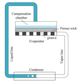
Loop heat pipe was first invented by Maydanik in 1972[1]. It was mainly used in aerospace science originally[2]. Since then, due to its excellent heat transfer performance, loop heat pipe has been widely applied to the thermal control of spacecrafts and electronic components[3-8]. Loop heat pipe consists of an evaporator, a condenser, a compensation chamber, vapor line and liquid line, as shown in Fig. 1. Evaporator is the key component of a loop heat pipe[9]. The porous wick embedded in the evaporator is capable of motivating the fluid circulation in the system by capillary force[10-11].Because of the phase change process of the working fluid, the heat transfer efficiency is greatly improved[12]. After the working fluid evaporates, the vapor will flow through the grooves of the evaporator into the vapor line. The compensation chamber attached to the evaporator is filled partially with liquid working fluid. It works as a protection against dry-out in the porous wick[13].
|
Figure 1 Schematic diagram of loop heat pipe system |
The performance of the evaporator is fatal to the efficiency of a loop heat pipe system. The vapor groove structure affects the heating area and the production of vapor. Therefore it has a significant impact on the overall performance of the evaporator[14]. Duncan et al.[15] investigated the heat transfer performance, the radius of the evaporation meniscus and the optimal value of charge mass for triangular-shaped groove. R. R. Riehl et al.[16]investigated the influence of geometry shape of grooves. By comparing heat transfer performance of evaporators with axial grooves and circumferential grooves, they found that circumferential grooves increased the evaporation area, therefore improved the heat transfer process. V. M. Kiseev et al.[17] conducted a comparative study on the "classic" scheme and "inverted meniscus" scheme of evaporation. By experimental methods, they found that both heat transfer coefficient and maximum heat flux of "inverted meniscus" scheme were better than those of "classic" scheme. Additionally, reducing the size and the length between concentric grooves would improve the heat transfer performance and increase the heat transfer coefficient. Evaporators with concentric grooves on the heated wall performed better than those with concentric grooves on the surface of the wick in terms of heat transfer coefficient. Zhang[18] simulated the flow and heat transfer process in a flat evaporator with three-dimensional model. The results indicated that when the porous wick was fully saturated, the heat transfer coefficient of the evaporator with grooves inside the porous wick was greater than that of the evaporator with grooves inside the solid wall. They also found that the evaporator achieved the best performance when the ratio between the depth and width of the groove was 1. Apart from the position of vapor grooves, the optimization of the structure of grooves would also improve the heat transfer performance of the evaporator. Wu[19] studied a novel skew-grooved wick structure for micro heat pipes. The results indicated that the maximum capillary force of the novel wick was 8.62% greater than that of the rectangle-grooved wick. The results also showed that the larger the degree of skewed angle was, the larger the capillary force was, but the larger the groove width was, the smaller the capillary force was. Based on experimental analysis, Wu et al.[20] found that increasing the amount of grooves, thereby increasing the surface area of the porous wick, would improve the heat transfer performance of the evaporator. Ghajar and Darabi[21] conducted an evaporative heat transfer analysis of a micro loop heat pipe with rectangular grooves. They found that narrower grooves performed better since the capillary force was higher because of the smaller width.
Current researches on the vapor groove structure of loop heat pipes with flat evaporators are mainly conducted via experimental or comparative methods[22-24]. There is a lack of insightful theoretical investigation of the geometric factors of the groove structure. This study aims to investigate the influence of geometry shape and size of the convex platform, as well as the ratio of convex platform to total heated surface, φ, in order to illustrate how to optimize the structure of vapor grooves considering the heat transfer performance of the evaporator of a loop heat pipe system.
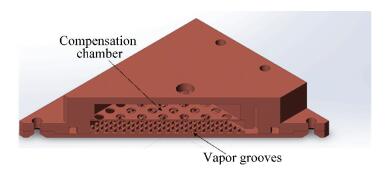
2 Modeling and Solving StrategyThere are a variety of evaporator forms in a loop heat pipe system. Flat and cylindrical evaporators are the most common ones. A typical flat evaporator of loop heat pipe consists of a compensation chamber and vapor grooves (as shown in Fig. 2). The porous wick was put between the compensation chamber and convex platforms. The convex platforms are capable of conducting heat from the heated wall to the porous wick. The working fluid absorbs heat and evaporates in the porous wick. Then the vaporized working fluid flows through the vapor grooves into the vapor line. According to previous studies, evaporators with grooves on the heated wall performed better in terms of heat transfer coefficient[18]. Therefore, the vapor grooves are graved on the heated wall in this study.
|
Figure 2 Schematic diagram of flat evaporator |
In this study, models of evaporators with different geometry shapes and sizes of convex platforms and ratios are built respectively. The convex platforms are of constant cross section. The maximum temperature and the homogeneity of temperature distribution are investigated.
The geometry size of the evaporator is 40 mm×36 mm×8.5 mm. The height of the convex platform is 1 mm. The thickness of the heated wall is 1.5 mm. The ratio between the convex platform and the heated surface is φ.
| $ \varphi = \frac{{{S_{{\rm{con}}}}}}{S} $ | (1) |
where, S is the surface area and Scon is the area of convex platforms.
The establishment of the mathematical model is built on the base of the following assumptions:
(1) The evaporation takes place at the surface of the porous wick facing to the vapor grooves.
(2) The heat influx is completely consumed by the evaporation of the working fluid. Heat leakage of the evaporator is neglected.
(3) To emphasize the impact of the three factors mentioned above, a material with thermal conductivity as low as 80 W/(m·K) is selected.
(4) The working fluid flows out of the evaporator from the lateral side. The area of the outlet is Sol.
| $ {S_{ol}} = 40 \times 1 = 40\;{\rm{m}}{{\rm{m}}^2} $ |
The temperature field and velocity field are described by energy, mass and momentum conservation equations.
In the fluid region, mass conservation equation is:
| $ \nabla \left( {{\rho _{vp}}V} \right) = 0 $ | (2) |
Momentum and energy conservation equations are expressed as:
| $ {\rho _{vp}}\left( {V \cdot \nabla V} \right) = - \nabla p + \nabla \left( {{\mu _{vp}}\nabla V} \right) $ | (3) |
| $ {\rho _{vp}}{c_p}\left( {V\nabla T} \right) - {\lambda _{vp}}{\nabla ^2}T = 0 $ | (4) |
where, ρvp(kg/m3) is the density of the vapor, μvp(N/(m2·s)) is the dynamic viscosity of the vapor, cp(kJ/(kg·K)) is the specific heat capacity of the vapor, and λvp(W/(m·K)) is the thermal conductivity of the vapor, T is temperature (K), p is pressure (Pa).
In the solid heated wall, a model of three-dimension steady heat conduction without heat source is built. The energy conservation equation, namely the heat conduction differential equation, is expressed as:
| $ \rho {\lambda _s}{\nabla ^2}T = 0 $ | (5) |
where λs(W/(m·K)) is the thermal conductivity of the solid material.
For the heat transfer process, a steady heat flux of 80 W inflows at the heated surface. The evaporating temperature is set at 343 K, and the corresponding evaporating pressure is 0.031 MPa. Correspondingly, the temperature at the interface between the vapor grooves and the porous wick is 343 K.
For the boundary condition of the velocity field, the upper surface of vapor grooves is taken as pressure reference, and the lateral side of the evaporator is taken as flow outlet.
The velocity of the working fluid v (m/s) is obtained from the following equation:
| $ v = \frac{Q}{{{\gamma _{fl}}{S_{ol}}{\rho _{fl}}}} $ | (6) |
where γfl(J/kg) and ρfl(kg/m3) are the latent heat and density of the fluid, and Sol is the area of the outlet surface.
To compare the flow friction to heat transfer resistance for the overall heat transfer performance of the evaporator, entropy generation is chosen as the evaluation index.
The total entropy generation of heat transfer resistance Sg, ht(W/K) is calculated[25] as:
| $ {S_{g,ht}} =\iiint_{\mathit{\Omega}1}{ \frac{{{\rho _s}{\lambda _s}}}{{{T^2}}}{\left| {\nabla T} \right|^2}}{\rm{d}}v $ | (7) |
The total entropy generation caused by flow friction Sg, ff(W/K) is calculated[26-28] as:
| $ {S_{g,ff}} = \iiint_{\mathit{\Omega}2}{ \frac{{2\left( {1 - {\rho _{vp}}} \right){\mu _{vp}}}}{T}{\left| {\nabla V} \right|^2}}{\rm{d}}v $ | (8) |
In Eqs.(7) and (8), Ω1 denotes the domain of convex platform and bottom matrix, and Ω2 denotes the domain of vapor grooves.
The conservation equations are solved numerically by COMSOL MULTIPHYSICS V4.2. Unstructured mesh is generated for the domain of the study. The number of elements varies from 759 837 to 2 514 719. The minimum element quality varies from 0.003 26 to 0.017 08. And the range of average element quality is 0.604 5-0.635 2. Mesh independence is checked out by simulating with finer meshes. When the number of elements was doubled, the average temperature of convex platforms was less than 0.1%.In the process of the numerical solution, velocity field and pressure field are solved independently with build-in PARDISO stationary solver. Segregated solver MUMPS is employed for solving the energy conservation equation to accelerate the convergence.
3 Numerical Results and Discussion 3.1 Comparison of Heat Transfer Resistance and Flow FrictionThe worst working condition for flow friction, namely the model of 1 mm×1 mm square platforms of which φ=0.25 is taken to investigate the significance of flow friction in the simulation. In the model, the distances between the platforms where the vapor has to flow through are the narrowest among all the models, which would cause the highest flow friction. According to the results of calculation presented by Eqs.(7) and (8), the total entropy generation of heat transfer resistance is 0.025 6 J, and the total entropy generation caused by flow friction is 2.99 E-11 J. The heat transfer resistance is far more significant than flow friction. Therefore, the flow friction is neglected in the subsequent simulations.
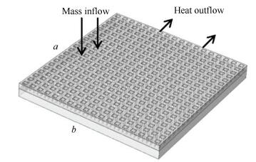
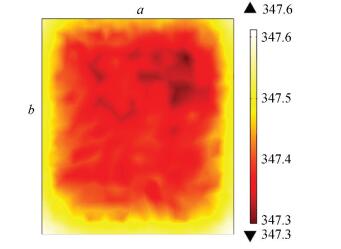
3.2 Impact of Geometry Shapes of the Convex PlatformsA model of 1 mm×1 mm square platforms is established, of which φ=0.25. The number of the platforms is 18×20. The structure of the model is shown in Fig. 3, and the temperature color map of the bottom surface is shown in Fig. 4.
|
Figure 3 Model structure diagram of square 1 mm×1 mm platform with φ=0.25 |
|
Figure 4 Temperature color map of square 1 mm×1 mm platform with φ=0.25 |
As the temperature color map shows, there is no obvious difference between the temperature of the platform and groove. The range of temperature of the bottom surface is 347.3-347.6 K. Moreover, the highest temperature area is on the side b due to the high flow resistance.
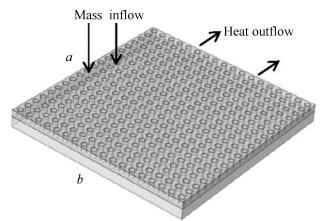
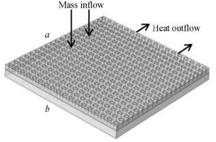
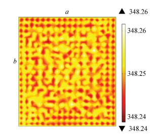
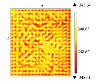
During shape comparison, circle, oval and square convex platforms are of the same area and position. The model structures of circle and oval platforms are shown in Fig. 5 and Fig. 6. With heat load and other conditions being exactly the same as square platforms model, temperature color maps of the bottom surface of circle and oval platforms are obtained and shown in Fig. 7 and Fig. 8. It is also found from the results that the temperature of the platform region is lower than the groove region, with a temperature difference of 1 K. There is no obvious difference of temperature distribution along the fluid flow direction.
|
Figure 5 Model structure diagram of circle platforms with φ=0.25 |
|
Figure 6 Model structure diagram of oval platforms with φ=0.25 |
|
Figure 7 Temperature color map of circle platforms with φ=0.25 |
|
Figure 8 Temperature color map of oval platforms with φ=0.25 |
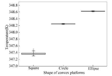
To visualize the temperature distribution of different models, a box-whisker plot of maximum, upper quartile, median, lower quartile and minimum temperature is drawn from the numerical results, which is exhibited in Fig. 9. According to Fig. 9, the median temperature of the model with square platforms is approximately 1 K lower than models with circle and oval platforms. But the temperature distribution of the model with square platforms is less homogeneous than the other two. This is because square convex platforms can significantly enhance the turbulence of fluid flow and intensify the heat convection.
|
Figure 9 Temperature distribution of different geometry shapes of convex platforms |
3.3 Impact of the Size of the Convex Platforms
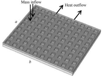
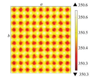
In order to investigate the impact of the size of convex platforms on the heat transfer performance of the evaporator, models of 1 mm×1 mm and 2 mm×2 mm square platforms are established. The ratio φ of both models is 2.5. The numbers of the platforms of 1 mm×1 mm and 2 mm×2 mm models are 18×20 and 9×10. The structure and simulated result of 1 mm×1 mm model are shown in Fig. 3 and Fig. 4. The structure of the 2 mm×2 mm model is shown in Fig. 10, and the temperature color map of the bottom surface is shown in Fig. 11.
|
Figure 10 Model structure diagram of square 2 mm×2 mm platform with φ=0.25 |
|
Figure 11 Temperature color map of square 2 mm×2 mm platform with φ=0.25 |
As the temperature color maps show, with the increase of size of convex platforms, the range of temperature distribution rose from 347.3-347.6 K to 350.3-350.6 K. It is also noticeable that the temperature difference between the platform region and the groove region of 2 mm×2 mm model is more profound than 1 mm×1 mm model. In the 2 mm×2 mm model, the temperature distribution along the fluid flow direction is nearly the same.
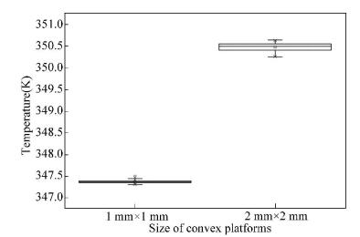
Similarly, a box-whisker plot of the two models is obtained and shown in Fig. 12. The average temperature of the 2 mm×2 mm model is approximately 3 K higher than 1 mm×1 mm, and its temperature distribution is less homogeneous.
|
Figure 12 Temperature distribution of different sizes of convex platforms |
Based on the theory of heat transfer, the heat load is conducted from the bottom surface through the convex platform to the porous wick. Subsequently, the energy is shared by the evaporation of the working fluid and flows out of the evaporator by convection. Smaller convex platforms increased the relative surface areas, which will enhance the heat transfer from the grooves to the solid convex platforms. However, with the same total area of convex platforms, the smaller the platforms, the narrower the distances between the platforms where the vapor has to flow through, which would cause a higher flow friction. According to the simulated results, the enhancement of heat transfer performance brought by the decrease of the size of convex platforms outweighs the negative effect caused by the increase of flow friction. This accords with the calculation result in Section 3.1.
3.4 Impact of φ on the Convex PlatformsTo investigate the influence of φ on the performance of the evaporator, three models of square 2 mm×2 mm convex platforms are established. The ratios of the three models are 0.1, 0.2, 0.25 and their structures are shown in Fig. 13, Fig. 14 and Fig. 10, respectively. The box-whisker plot shown in Fig. 15 is used to compare the results of the three models.
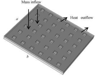
|
Figure 13 Model structure diagram of square 2 mm×2 mm platform with φ=0.1 |
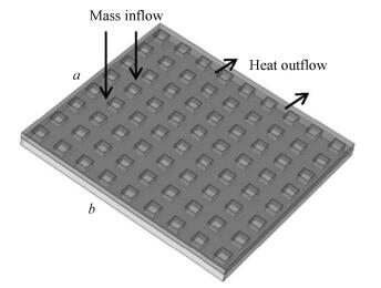
|
Figure 14 Model structure diagram of square 2 mm×2 mm platform with φ=0.2 |
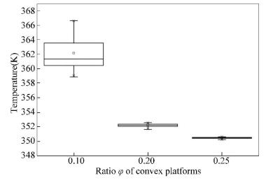
|
Figure 15 Temperature distribution of different ratio φ |
The temperature color maps are shown in Fig. 11, Fig. 16 and Fig. 17. The temperature color maps demonstrate that the temperature of the groove region is higher than that of the platform region. This is because wider grooves weaken the heat conduction process. Likewise, Fig. 16 shows that the temperature of the upper side and downside of the surface is higher than the central area due to the relatively far distance from convex platforms.
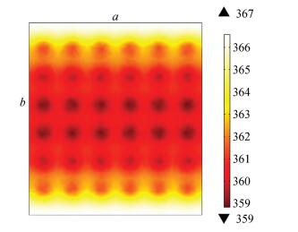
|
Figure 16 Temperature color map of square 2 mm×2 mm platform with φ=0.1 |
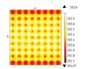
|
Figure 17 Temperature color map of square 2 mm×2 mm platform with φ=0.2 |
As is shown in Fig. 15, when φ=0.1, 0.2 and 0.25, the median temperatures are approximately 361 K, 352 K and 351 K respectively. Additionally, the range of temperature distribution of the model with φ=0.1 is 359-367 K, while the differences between the maximum and minimum temperature of models with φ=0.2 and 0.25 is less than 2 K and 1 K. Therefore, it may be concluded that the increase of φ will lead to lower maximum and median temperature, as well as more uniform temperature distribution.
4 ConclusionsTo investigate the impact of vapor groove structures on the performance of the evaporator of a loop heat pipe system, models with convex platforms of different shapes, sizes and ratios are established. The temperature fields and velocity fields are obtained by solving energy, mass and momentum conservation equations under steady conditions. The numerical results indicate that among the three investigated shapes of convex platforms, square platforms enhance the turbulence of the fluid flow most significantly, resulting in the lowest temperature. The decrease of the size of platforms and the increase of area ratio between the convex platforms and the heated bottom plate (φ) can lower temperature and improve temperature distribution homogeneity of the heated bottom plate. Among the three factors, φ exerts the greatest impact on the performance of the evaporator. Therefore, in the designing of flat evaporators of loop heat pipes, convex platform structures which enhance the turbulence of the fluid flow and have smaller geometry sizes as well as bigger ratio φ, will significantly improve the heat transfer performance.
| [1] |
Maydanik Y F, Chernysheva M A, Pastukhov V G. Review: Loop heat pipes with flat evaporators. Applied Thermal Engineering, 2014, 67: 294-307. DOI:10.1016/j.applthermaleng.2014.03.041 ( 0) 0)
|
| [2] |
Vlassov V V, Riehl R R. Modeling of a loop heat pipe for ground and space conditions. Proceedings of the 35th International Conference on Environmental Systems. Rome, 2005. 10-15. DOI: 10.4271/2005-01-2935.
10. 4271/2005-01-2935
( 0) 0)
|
| [3] |
Hamdan M, Elnajjar E. Thermodynamic analytical model of a loop heat pipe. Heat and Mass Transfer, 2009, 46(2): 167-173. DOI:10.1007/s00231-009-0555-0 ( 0) 0)
|
| [4] |
Özdemir M. An experimental study on an oscillating loop heat pipe consisting of three interconnected columns. Heat and Mass Transfer, 2007, 43(6): 527-534. DOI:10.1007/s00231-006-0128-4 ( 0) 0)
|
| [5] |
Liu Z C, Liu W, Nakayama A. Flow and heat transfer analysis in porous wick of CPL evaporator based on field synergy principle. Heat and Mass Transfer, 2007, 43(12): 1273-1281. DOI:10.1007/s00231-006-0213-8 ( 0) 0)
|
| [6] |
Zhang Weibao. Study on Heat Transfer Performance of LHP. Guang Zhou: South China University of Technology, 2010. 12-77.
( 0) 0)
|
| [7] |
Adoni A A, Ambirajan A, Jasvanth V S, et al. Theoretical and experimental studies on an ammonia-based loop heat pipe with a flat evaporator. IEEE Transactions on Components and Packaging Technologies, 2010, 33(2): 478-487. DOI:10.1109/TCAPT.2010.2042056 ( 0) 0)
|
| [8] |
Lu Xiangyou, Hua Zezhao, Liu Meijing, et al. Analysis of heat transfer of loop heat pipe used to cool high power LED. Science in China Series E: Technological Sciences, 2009, 52(12): 3527-3532. DOI:10.1007/s11431-009-0286-y ( 0) 0)
|
| [9] |
Huang X M, Liu W, Nakayama A, et al. Modeling for heat and mass transfer with phase change in porous wick of CPL evaporator. Heat and Mass Transfer, 2005, 41(7): 667-673. DOI:10.1007/s00231-004-0609-2 ( 0) 0)
|
| [10] |
Xin Gongming, Cui Kehang, Zou Yong, et al. Development of sintered Ni-Cu wicks for loop heat pipes. Science in China Series E: Technological Sciences, 2009, 52(6): 1607-1612. DOI:10.1007/s11431-009-0180-7 ( 0) 0)
|
| [11] |
Li Jinwang, Zou Yong, Zhao Liang, et al. Capillary pumping characteristics of porous wick for loop heat pipe. Journal of Engineering Thermophysics, 2010, 31(5): 839-841. ( 0) 0)
|
| [12] |
Kaya T, Hoang T T. Mathematical modeling of loop heat pipes and experimental validation. Journal of Thermophysics and Heat Transfer, 1999, 13(3): 314-320. DOI:10.2514/2.6461 ( 0) 0)
|
| [13] |
Riehl R R, Siqueira T C P A. Heat transport capability and compensation chamber influence in loop heat pipes performance. Applied Thermal Engineering, 2006, 26(11-12): 1158-1168. DOI:10.1016/j.applthermaleng.2005.10.037 ( 0) 0)
|
| [14] |
Riehl R R. Comparing the behavior of a loop heat pipe with different elevations of the capillary evaporator. Proceedings of the 34th International Conference on Environmental Systems. Colorado Springs, 2004. paper 2004-01-2510. DOI: 10.4271/2004-01-2510.
( 0) 0)
|
| [15] |
Duncan A B, Peterson G P. Charge optimization for a triangular-shaped etched micro heat pipe. Journal of Thermophysics and Heat Transfer, 1995, 9(2): 365-368. DOI:10.2514/3.670 ( 0) 0)
|
| [16] |
Riehl R R, dos Santos N. Loop heat pipe performance enhancement using primary wick with circumferential grooves. Applied Thermal Engineering, 2008, 28(14-15): 1745-1755. DOI:10.1016/j.applthermaleng.2007.11.005 ( 0) 0)
|
| [17] |
Kiseev V M, Vlassov V V, Muraoka I. Experimental optimization of capillary structures for loop heat pipes and heat switches. Applied Thermal Engineering, 2010, 30(11-12): 1312-1319. DOI:10.1016/j.applthermaleng.2010.02.010 ( 0) 0)
|
| [18] |
Zhang Xianfeng, Li Xuanyou, Wang Shuangfeng. Three-dimensional simulation on heat transfer in the flat evaporator of miniature loop heat pipe. International Journal of Thermal Sciences, 2012, 54: 188-198. DOI:10.1016/j.ijthermalsci.2011.12.002 ( 0) 0)
|
| [19] |
Wu Juhong. Study of a Novel Skew-Grooved Wick Structure for Micro Heat Pipes. Guang Zhou: South China University of Technology, 2012. 11-80.
http: //cdmd. cnki. com. cn/Article/CDMD-10561-1012451255. htm
( 0) 0)
|
| [20] |
Wu S C, Wang D, Gao J H, et al. Effect of the number of grooves on a wick's surface on the heat transfer performance of loop heat pipe. Applied Thermal Engineering, 2014, 71(1): 371-377. DOI:10.1016/j.applthermaleng.2014.06.042 ( 0) 0)
|
| [21] |
Ghajar M, Darabi J. Evaporative heat transfer analysis of a micro loop heat pipe with rectangular grooves. International Journal of Thermal Sciences, 2014, 79: 51-59. DOI:10.1016/j.ijthermalsci.2013.12.014 ( 0) 0)
|
| [22] |
Wang Dongdong, Liu Zhichun, Shen Jun, et al. Experimental study of the loop heat pipe with a flat disk-shaped evaporator. Experimental Thermal and Fluid Science, 2014, 57: 157-164. DOI:10.1016/j.expthermflusci.2014.04.017 ( 0) 0)
|
| [23] |
Wang Shuangfeng, Huo Jiepeng, Zhang Xianfeng, et al. Experimental study on operating parameters of miniature loop heat pipe with flat evaporator. Applied Thermal Engineering, 2012, 40: 318-325. DOI:10.1016/j.applthermaleng.2012.02.029 ( 0) 0)
|
| [24] |
Singh R, Akbarzadeh A, Mochizuki M. Operational characteristics of a miniature loop heat pipe with flat evaporator. International Journal of Thermal Sciences, 2008, 47(11): 1504-1515. DOI:10.1016/j.ijthermalsci.2007.12.013 ( 0) 0)
|
| [25] |
Bejan A. Entropy generation minimization:The new thermodynamics of finite-size devices and finite-time processes. Journal of Applied Physics, 1996, 79(3): 1191-1218. DOI:10.1063/1.362674 ( 0) 0)
|
| [26] |
Li Chunxi, Yin Pan, Ye Xuemin, et al. Effect of abnormal blade incidence on internal entropy generation in axial-flow fans. Journal of Chinese Society of Power Engineering, 2012, 32(12): 947-953. DOI:10.3969/j.issn.1674-7607.2012.12.007 ( 0) 0)
|
| [27] |
Wang Songling, Zhang Lei, Ye Xuemin, et al. Performance optimization of centrifugal fan based on entropy generation theory. Proceedings of the CSEE, 2011, 31(11): 86-91. ( 0) 0)
|
| [28] |
Yang Wei, Sun Yue, An Jing, et al. Study on flow field number of high pressure nozzle and entropy generation. Journal of Water Resources & Water Engineering, 2011, 22(2): 66-68. ( 0) 0)
|
 2017, Vol. 24


