2. School of Mechatronics Engineering, Harbin Institute of Technology, Harbin 150080, China
As an important electromechanical system, the precision centrifuge is commonly used to test and calibrate the model parameters of an accelerometer[1-3]. In order to maintain the orientation of the unit under test (UUT), a scheme of 2-DOF precision centrifuge is proposed, that is, the mainshaft system is used to produce a high overload environment and the countershaft system is used to counteract the rotation of the mainshaft by rotating in the opposite direction. High operation smoothness is the most significant performance index for the equipment and the essential condition to achieve synchronous control of the two shafts, however, the existence of dynamic unbalance brings obstacles for realizing the performance.
For continuous rotary machines, unbalance of the body always causes undesirable vibrations, which leads to nonsmooth motions, periodic disturbances as well as uncertain dynamics and even instability. In addition, unbalance existing in the countershaft may cause the problem of actuator saturation due to the uneven friction of the bearings in case of high overload environment. To overcome these drawbacks, the unbalance magnitude of the rotary shaft systems needs to be reduced to a low level. Actually, many identification algorithms and correction methods have been developed and introduced to solve the problem in the field of industry manufacture and high precision servo systems[4-15]. For the precision centrifuge with two degrees of freedom, the phenomena of unbalance exist in both mainshaft and countershaft system simultaneously. By utilizing space vector algorithm, the former is reduced to a great extent[16]. However, the latter is more difficult since it is impossible to install any sensors associated to the countershaft system, which is the main problem we focus on in this paper.
As the most famous and widely used multibody dynamics software, ADAMS improves engineering efficiency and reduces product development costs by enabling early system-level design validation[17-18]. By utilizing finite element analysis (FEA), it is convenient for engineers to investigate different loading conditions, study the dynamics of moving parts and also to integrate mechanical components, pneumatics, hydraulics, electronics, and control systems technologies to build and test virtual prototypes that accurately account for the interactions between these subsystems.
In this paper, the identification of unbalance is investigated, aiming at the countershaft system of the precision centrifuge with two degrees of freedom. According to the characteristics of the UUT installed in the countershaft system, the identification procedure breaks down into two stages: phase determination and amplitude calculation. The former is to provide the phase where the unbalance is existent by gradual subdivision design of experiment, and the latter focuses on calculating the amplitude of the unbalance. Inspired with the unbalance identification algorithm subject to the mainshaft system, the novel identification strategy is proposed by utilizing two displacement transducers which are installed associated to the mainshaft[16]. Due to the multi-source property and complexity of the problem, numerical simulation is by no means a reasonable and feasible choice. Therefore, the dynamical model of the arm-typed precision centrifuge with two degrees of freedom is established with ADAMS and the effectiveness of our work is illustrated by some numerical simulations in ADAMS environment, as well as experimental studies.
The rest of the paper is organized as follows. In Section 2, the structure of the arm-typed precision centrifuge with two degrees of freedom is introduced and the characteristic of the UUT is reviewed with respect to the configuration. The main results are developed in Section 3, where the concrete identification strategy of dynamic unbalance is proposed by using two axis-layout displacement transducers. In order to illustrate the validity of the strategy, some simulation and comparison cases are presented in Section 4. In Section 5, the strategy is applied to the real system and some experimental studies are developed. Section 6 concludes the whole paper.
2 Problem FormulationWe begin this section with the introduction of the arm-typed precision centrifuge with two degrees of freedom, and then the characteristic of the UUT is analyzed.
2.1 Description of 2-DOF Arm-Typed Precision CentrifugeThe configuration of the precision centrifuge with two degrees of freedom is shown in Fig. 1, which is mainly composed of the mainshaft system, load part (i.e., the countershaft system), arm, weight part, bearings, two motors and the base. The inertial component, or UUT, is mounted in the load part associated to the system of the countershaft system. The mainshaft is used to offer the high overload environment, and the weight part, fixed-installed, has the same structure and mass properties with the countershaft, which is used to correct the mainshaft system of the precision centrifuge by adding or reducing masses. Both of the mainshaft and countershaft are driven by permanent magnet synchronous motors (PMSMs), while the information of the angular position is measured by a photoelectric encoder and an inductosyn, respectively.

|
Figure 1 Structure of the 2-DOF arm-typed precision centrifuge |
For maintaining the orientation of the UUT in the inertial space, the countershaft is used to offset the rotation of the mainshaft, that is, the angular velocities of the mainshaft and the countershaft are ω and -ω. In the axial direction, two non-contact eddy-current displacement transducers S1 and S2 are mounted at two ends of the mainshaft, which are utilized to measure the distance variation between the mainshaft profile and the detectors of the transducers, i.e., the vibration of the mainshaft system can be obtained by calculation.
Some parameters of the physical dimension used throughout this paper are also given in Fig. 1, where the radius and width of the arm of the 2-DOF precision centrifuge are RM and L, and the radius of the load part is RC. The intersection point of the mainshaft and the neutral surface of the arm is denoted by OA, and the rotation center of the mainshaft system is denoted by OR. The distance between OA and OR, two transducers S1 and S2 in the axial direction are denoted by H and h, respectively.
2.2 Unbalance Analysis of Countershaft SystemAs a mass property, unbalance exists when the principal inertia axis does not coincide with the rotation axis. Based on the rotation axis motion characteristics, the dynamic unbalance can be classified to static unbalance, couple unbalance, quasi-static unbalance and dynamic unbalance, as shown in Fig. 2.

|
Figure 2 Four types of unbalance |
Static unbalance is known as force unbalance, and it has the additional condition that the axis of rotation be parallel to the central principal axis, as shown in Fig. 2(a). Couple unbalance is a specific condition that exists when the central principal axis of inertia is not parallel to the axis of rotation with an additional condition that the mass center lie on the axis of rotation, as shown in Fig. 2(b). As a combination of static and couple unbalance, dynamic unbalance is the most general case of unbalance, in which case the central principal axis is neither parallel nor intersectant to the axis of rotation, as shown in Fig. 2(d). Quasi-static unbalance is a special form of dynamic unbalance where static and couple unbalance vectors locate in the same plane, with the mass center being not on the axis of rotation and the central principal axis intersecting the axis of rotation.
Due to the imperfect factors in manufacturing and assembling, the uneven distribution of body mass in the countershaft system is unavoidable in real applications, which means that the principal inertia axis and the axis of rotation will not coincide. Due to the theory of unbalance, the inconsistence introduces extra force and/or couple inevitably act on the load part, leading to various unexpected vibrations and noises.
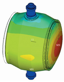
The countershaft system of the precision centrifuge with two degrees of freedom consists of two parts: the mechanical body and the unit under test, which is installed inside the body. The status of the mechanical body is relatively ideal, and the residual dynamic unbalance can be restricted to a low level by elaborate design and machining process, as shown in Fig. 3. However, the mass distribution of the UUT is uncontrollable and difficult to restrain in the process of production and assembly, which leads to the dynamic unbalance of the load part.
|
Figure 3 FEA of mechanical body without unit under test |
Obviously, there exists static unbalance as well as couple unbalance in the countershaft system. Fortunately, due to the design standard of the UUT, the unbalance of the countershaft system mainly appears as static unbalance, i.e., the mass with respect to the static unbalance is much larger than the one of couple unbalance in the practical case. Without loss of generality, the following assumption is satisfied that
| $ {{m}_{\rm{static}}}\ge 10{{m}_{\rm{couple}}} $ | (1) |
where the static and couple unbalance are denoted by mstatic and mdouble, respectively.
3 Strategy of Unbalance Identification and CorrectionUnbalance is a vector, which includes both phase and amplitude information, therefore the aim of unbalance identification is to find out the phase where the unbalance exists and to calculate its amplitude. In this section, the main contribution of this paper is proposed and the identification procedure is developed. With respect to the countershaft of the arm-typed centrifuge, the impact analysis of the unbalance is investigated firstly.
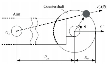
3.1 Impact Analysis of Unbalance in CountershaftDue to the configuration of the arm-typed centrifuge, the phase of the unbalance of the mainshaft system is located in the direction of 0°, or 180° (see Ref.[16]). Assume that the static unbalance existing in the countershaft system locates on the position of θ, as shown in Fig. 4. Thus, the centrifugal forces caused by unbalance mass of the centrifuge are shown in Fig. 5, where mM and mC denote the unbalance masses of the mainshaft and the countershaft system, respectively. The resultant force acting on mM and mC is F= FM+ FC, and the amplitude of F is obtained as:
| $ \begin{align} & \mathit{F}={{\omega }^{2}}\{2{{m}_{C}}\left( {{m}_{C}}+{{m}_{M}}{\rm{cos}}{{U}_{MP}} \right){{R}_{M}}{{R}_{C}}\rm{cos}\theta + \\ & \ \ \ \ \ \ \ \ \ \ \ {{\left( {{m}_{C}}+{{m}_{M}}{\rm{cos}}{{U}_{MP}} \right)}^{2}}R_{M}^{2}+m_{C}^{2}R_{C}^{2}{{\}}^{\frac{1}{2}}} \\ \end{align} $ | (2) |
|
Figure 4 Centrifugal force of the static unbalance case |

|
Figure 5 Two cases of centrifugal forces with mM and mC |
where UMP∈{0, π} denotes the unbalance phase of the mainshaft system.
Here, an illustrated example is considered, as shown in Fig. 5(a), where the unbalance phase of the mainshaft system is 0°. The curve of F with respect to θ is shown in Fig. 6(a), where a maximum value of F occurs when θ=0°. Analogously, a minimum value can be obtained at the same angular position in the case that UMP=180°, as shown in Fig. 5(b) and Fig. 6(b), where mM > mC, obviously.

|
Figure 6 Amplitude of F with respect to θ |
It should be noted that the tilt angle of the rotary mainshaft system with a high angular velocity is in direct proportion to the resultant of the centrifugal forces acting on itself, which in turn can be utilized to develop the identification strategy for the countershaft system of the precision centrifuge with two degrees of freedom in the sequel.
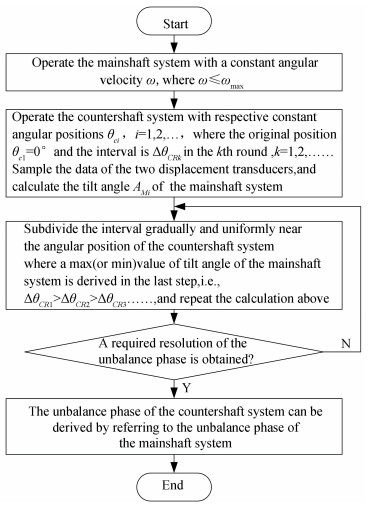
3.2 Determination of Unbalance PhaseThe unbalance phase can be determined by using a gradual subdivision method and the specific process is given in Fig. 7, where ωmax denotes the maximum angular velocity of the mainshaft system.
|
Figure 7 Flow chart of unbalance phase identification |
According to the unbalance status of the mainshaft system, the unbalance phase of the countershaft can be derived as:
| $ \left\{ \begin{align} & {{U}_{CP}}=\underset{~{{\theta }_{Ci}}, ~i=1, 2, \ldots }{\mathop{\rm{argmax}}}\, \ {{A}_{M}}, ~{\rm{if}}\ {{U}_{MP}}={{0}^{\circ }} \\ & {{U}_{CP}}=\underset{~{{\theta }_{Ci}}, ~i=1, 2, \ldots }{\mathop{\rm{argmin}}}\, ~{{A}_{M}}, ~{\rm{if}}\ ~{{U}_{MP}}={{180}^{\circ }} \\ \end{align} \right. $ | (3) |
where AM∈{AMi} is the set of tilt angles at sequential angular positions θCi, UCP denotes the unbalance phase of the countershaft system.
Remark 1 It should be noted that the unbalance identification for the countershaft system is independent from the unbalance amplitude of the mainshaft system, but its unbalance phase should be known. Actually, this assumption is reasonable as well.
Remark 2 A correlation filtering algorithm can be introduced to estimate the unbalance phase by using limited subdivisions, which reduces the workload effectively.
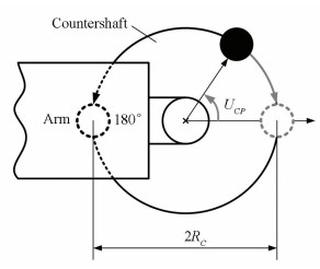
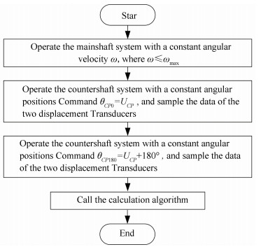
3.3 Calculation of Unbalance AmplitudeWithout loss of generality, assume the phase of unbalance UCP is derived in the first stage, Fig. 8 shows the sketch drawing of the next stage for calculating the amplitude of unbalance, and the flow chart is given in Fig. 9.
|
Figure 8 Sketch drawing of the calculation process |
|
Figure 9 Flow chart of unbalance amplitude calculation |
In the sequel, the calculation algorithm is presented concretely. The outputs of the transducers S1 and S2 are sampled with respect to θM denoted by r1(θM) and r2(θM), respectively, where θM denotes the angular position of the mainshaft system. By utilizing correlation filtering method, the fundamental components of r1(θM) and r2(θM) can be derived as r1f(θM) and r2f(θM), where the vector form is denoted by r1 and r2. Thus in the case where the countershaft system locates at θCP0, the vector of the rotating mainshaft system can be calculated by utilizing a spatial vector algorithm as:
| $ \mathit{\boldsymbol{r}}={{\mathit{\boldsymbol{r}}}_{1}}\rm{-}{{\mathit{\boldsymbol{r}}}_{2}} $ | (4) |
Analogously, the vector of the rotating mainshaft system in the case where the countershaft system locates at θCP180 can be calculated as:
| $ \mathit{\boldsymbol{t}}={{\mathit{\boldsymbol{t}}}_{1}}\rm{-}{{\mathit{\boldsymbol{t}}}_{2}} $ | (5) |
where t1 and t2 denote the vectors of fundamental components of the transducers S1 and S2 when the countershaft is controlled at position point θCP180. The corresponding variance of the mainshaft system between θCP0 and θCP180 can be obtained as:
| $ \mathit{\boldsymbol{u}}=\mathit{\boldsymbol{r-t}} $ | (6) |
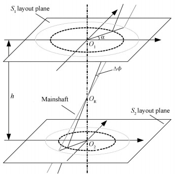
which is caused by the variance of the mass distribution of the countershaft rotating from θCP0 to θCP180. Denote the amplitude of the vector u by Au, measured in volts (V), the variance of the geometric tilt angle of the mainshaft system can be calculated according to Fig. 10 as follows:
| $ \Delta \phi =\frac{648\ 000C{{A}_{u}}}{{\rm{ }}\pi h} $ | (7) |
|
Figure 10 Variance of the geometric tilt angle of the mainshaft system |
where C denotes the proportionality coefficient of the eddy-current displacement transducer, with unit μm/V. Based on the moment equilibrium condition of the mainshaft system, we have:
| $ {{K}_{\phi }}\Delta \phi =2m{{R}_{C}}{{\omega }^{2}}H+2m{{g}_{0}}{{R}_{C}} $ | (8) |
where Kϕ is the angular stiffness of the mechanical bearings of the mainshaft system, with unit Nm/arcsec, and g0 denotes the local acceleration of gravity. Accordingly, the unbalance amplitude of the countershaft system can be calculated as:
| $ {{U}_{CA}}=m{{R}_{C}}=\frac{{{K}_{\phi }}\Delta \phi }{2\left( {{\omega }^{2}}H+{{g}_{0}} \right)} $ | (9) |
with unit kg·m.
Due to the sufficient angle stiffness of the mainshaft, it is sound to assume that H=(L+h)/2. Since the phase information is measured in the form of angular position of the mainshaft and the algorithm is also developed in spatial domain with a fixed angular position interval, the testing data are sampled and saved according to the angular position of the mainshaft system instead of the sampling time.
3.4 Single-plane CorrectionWhile unbalance has been identified and quantified, the correction is straightforward. The unbalance correction is a kind of mechanical operation associated to the rotating shafts, automatic or manual, by either adding or removing weights from the rotating elements. The ultimate aim is to reduce the uneven mass distribution so that the centrifugal forces and/or couples, the vibrations induced in the supporting structure and the noises are restrained to an acceptance level.
Dynamic unbalance is also referred to as two-plane unbalance, indicating that correction is always required in two planes to fully eliminate dynamic unbalance. However, due to the characteristics of the mass distribution of the UUT, which we discussed in Section 2, the unbalance of the countershaft system is mainly performed as static unbalance. Thus, according to the balance theory of mechanic rotor, a single plane is sufficient to shift the mass center onto the axis of rotation for the correction work[19-20].
In our case, automatic correction needs multi-actuator design, resulting in a more complex structure and low reliability, which has been proved to be obviously unrealistic, thus a manual-formed single-plane correction method is selected. A series of standard-size discs and small masses are produced, which can be installed directed on the load part or in the dovetail grooves designed on the load part. The corrective requests are as follows:
1) The operation of adding or removing trial weight is carried out in the plane of the mass center, i.e., the neutral plane of the countershaft system;
2) The size of trial weight is calculated based on the unbalance amplitude;
3) The position of trial weight is in the direction opposite the unbalance phase.
4 Numerical SimulationsIn this section, the dynamical model of the 2-DOF precision centrifuge is established with ADAMS, and the identification strategy proposed above is demonstrated by some numerical simulations and comparison cases.
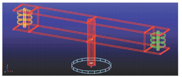
4.1 Modeling in ADAMSBy utilizing ADAMS, the dynamical model of arm-typed precision centrifuge with two degrees of freedom is established according to the structure and physical parameters as shown in Table 1. In this work, two rigid plank frames are built as a simplification of the arm, and three disks on each side of frames are the idealization of the load part and weight part in order to add unbalance mass to the countershaft system conveniently. Fig. 11 shows the three-dimensional graph of the model. Notice that the mainshaft system and the countershaft system are both supported by mechanical bearings.
| Table 1 Parameters list of the centrifuge |
|
Figure 11 Dynamical model in the framework of ADAMS |
In the framework of ADAMS, the displacement measurement of the non-contact transducer is accomplished by measuring the distance between a static point and a moving point, of which the static point is fixed to the base and the moving point is placed on the mainshaft system axis with the same height, moving synchronously with the axis.
Remark 3 In the practical situation, the distance between the displacement transducer and the bearing is small enough compared with the length of the mainshaft, thus it is reasonable to assume the distance between them in the axial direction is neglected.
4.2 Case Studies of Identification and CorrectionAccording to the analysis in Section 2, three different situations of unbalance are considered, i.e. static unbalance, quasi-static unbalance and dynamic unbalance, respectively. Without loss of generality, the mainshaft system angular velocity is chosen as ω=360 °/sec. In addition, according to the single-plane correction method described in subsection 3.4, a trial weight is added in the neutral plane of the countershaft, denoted by a cube in each case, to complete the correction.
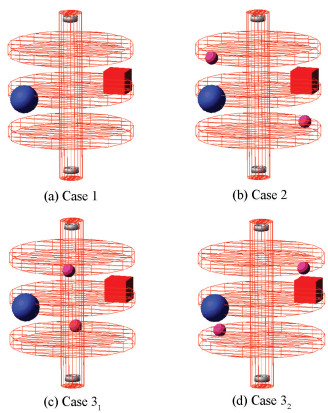
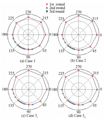
Case 1 Static Unbalance. As shown in Fig. 12(a), a ball Bs with the weight of 10 kg is placed at the edge of the middle disk on the load part at the angular position 120, which leads to a static unbalance of the countershaft system. The process of phase identification is shown in Fig. 13(a), and a cube weighing 9.959 3 kg is added to correct the mass distribution of the load part in the neutral surface.
|
Figure 12 Simulation cases |
|
Figure 13 Simulation process of phase determination |
Case 2 Quasi-Static Unbalance. Based on the configuration of static unbalance as in Case 1, two balls Bc1 and Bc2 both weighing 1 kg are added symmetrically on the same axial plane with Bs, which introduces a couple unbalance to the countershaft system, as shown in Fig. 12(b). According to the definition of unbalance, the formative status is quasi-static unbalance. Fig. 13(b) shows the result of phase determination and a cube weighing 10.554 3 kg is added to the neutral surface for balance correction.
Case 3 Dynamic Unbalance. Analogously, a dynamic unbalance case is considered, where the balls Bc1 and Bc2 are added symmetrically on a different axial plane with Bs, which leads to the status of dynamic unbalance, as shown in Fig. 12(c). The procedure of phase determination is illustrated in Fig. 13(c) and the correction mass is 10.461 6 kg. Notice that the phase error between static and couple unbalance in this case is set as 45°. By the same token, the case where the phase error is 90° is shown in Fig. 12(d) and Fig. 13(d), where the added cube is weighing 10.282 2 kg.
The comparison study of attenuation ratio with the strategy subject to different unbalance cases is demonstrated in Table 2, where ΔϕBC denotes the tilt angle before balance correction and ΔϕAC denotes the one after correction. Obviously, the unbalances of the countershaft system are all reduced to a great extent, and the algorithm proposed in this paper is verified by the simulations.
| Table 2 Comparison demonstrations |
5 Experimental Illustrations 5.1 Experiment Setup and Results
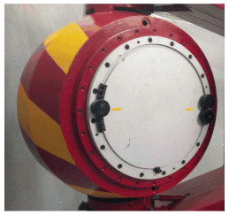
In this section, some experimental studies are implemented subject to the under-tuning precision centrifuge with two degrees of freedom and arm-typed structure, as shown in Fig. 14, and the strategy proposed in this paper is investigated.
|
Figure 14 A photograph of the countershaft system |
The unbalance phase of the mainshaft is 0°, which is verified before the unbalance identification of the countershaft system. According to the strategy proposed in section 3, UCP can be determined where the tilt angle of the mainshaft system reaches the maximum. We set the working angular velocity ω=180°/sec, and the angular intervals ΔθCR1=45°, ΔθCR2=15°, ΔθCR3=5° and ΔθCR4=1°, as shown in Fig. 15, where a partial enlarged drawing with an angular resolution of 1° is given, and the unbalance phase is educed as UCP=2°.

|
Figure 15 Experimental process of phase determination |
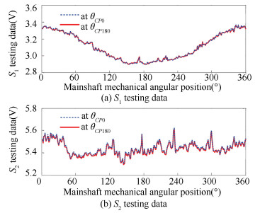
Based on the algorithm presented in Section 3, choose θCP0=2° and θCP180=182°. The signals of the eddy-current transducers with respect to the mechanical angular position of the mainshaft system are shown in Fig. 16, where UCA can be calculated as 10.847 kg.
|
Figure 16 The outputs of S1 and S2 at two positions |
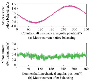
In order to illustrate the effectiveness of the method developed in this paper, a block of 10 kg is appended on the mechanical body of the countershaft at 180° and the drive current of the countershaft motor is measured and compared before and after the unbalance correction with the mechanical angular position of the countershaft system, as shown in Fig. 17. Obviously, the vibration of the countershaft system is reduced to a great extent which in turn demonstrates the validity of our work.
|
Figure 17 Comparison of current signal before and after unbalance correction |
5.2 Discussions
In the practical application, the tilt angle of the mainshaft system is calculated in the process of unbalance identification, which is a decisive parameter and depends largely on the accuracy of the displacement transducers and the signal to noise ratio since the outputs of the transducers always include measurement noise. The unbalance phase is determined mostly by the accuracy of the tilt angle calculation and the degree of subdivision. Besides, the result of the unbalance amplitude is influenced by concrete structural parameters H due to the uncertain rotation center OR and angular stiffness Kϕ of the mechanical bearings, in spite that the variations of these parameters are small amounts. In addition, the result of unbalance identification can be improved if the ratio of static unbalance to couple unbalance is greater associated to the countershaft system. Furthermore, all the trial weights are standard processing masses so that the effect of unbalance correction mainly depends on the size of the trial weights as well as the installation accuracy.
Due to the measuring error of the displacement transducers and the noisy environment, residual unbalance is ineluctable in real applications, in both phase and amplitude. The accuracy of unbalance identification, including the phase as well as the amplitude, can be improved with a higher balancing angular velocity of the mainshaft system. Also, in order to improve the accuracy and repeatability of the identification algorithm, multi-circle data should be sampled instead of one circle and an average or modified signal processing is recommended in the data collection process.
6 ConclusionsFor an under-tuning arm-typed precision centrifuge with two degrees of freedom, a new strategy for identifying and correcting the unbalance of the countershaft system is developed in this paper. Firstly, the unbalance phase is determined by a gradual subdivision design. Then, a novel algorithm is proposed, which utilizes two eddy-current displacement transducers to measure the tilt angle of the mainshaft system. Numerical simulations are implemented in ADAMS, where distinct unbalance cases are considered respectively. Experimental examples are given, and the results are consistent with the theoretical analysis and simulation results. Further research work should be taken into consideration in order to improve the accuracy as well as the efficiency of the identification process.
| [1] |
Wang S, Ren S. Relationship between calibration accuracy of error model coefficients of accelerometer and errors of precision centrifuge. Journal of Astronautics, 2012, 33(4): 520-526. ( 0) 0)
|
| [2] |
Wang S, Ren S. Calibration of cross quadratic term of gyro accelerometer on centrifuge and error analysis. Aerospace Science and Technology, 2015, 43(6): 30-36. DOI:10.1016/j.ast.2015.02.008 ( 0) 0)
|
| [3] |
Ren S, Wang S. Impacts of installation errors on the calibration accuracy of gyro accelerometer tested on centrifuge. Proceedings of the 2nd International Symposium on Instrumentation and Measurement, Sensor Network and Automation. Piscataway:IEEE, 2013, 914-918. DOI:10.1109/IMSNA.2013.6743426 ( 0) 0)
|
| [4] |
Tiwari R, Chougale A. Identification of bearing dynamic parameters and unbalance states in a flexible rotor system fully levitated on active magnetic bearings. Mechatronics, 2014, 24(3): 274-286. DOI:10.1016/j.mechatronics.2014.02.010 ( 0) 0)
|
| [5] |
Sudhakar G N D S, Sekhar A S. Identification of unbalance in a rotor bearing system. Journal of Sound and Vibration, 2011, 330(10): 2299-2313. DOI:10.1016/j.jsv.2010.11.028 ( 0) 0)
|
| [6] |
Castro H, Cavalca K, Camargo L, et al. Identification of unbalance forces by metaheuristic search algorithms. Mechanical Systems and Signal Processing, 2010, 24(6): 1785-1798. DOI:10.1016/j.ymssp.2009.11.012 ( 0) 0)
|
| [7] |
Castro H, Cavalca K, Bauer J, et al. Convergence on unbalance identification process based on genetic algorithm applied to rotating machinery. Proceedings of the 10th International Conference on Vibrations in Rotating Machinery. London:IMechE, 2012, 347-356. ( 0) 0)
|
| [8] |
Nagato K, Ide T, Ohno N, et al. Automatic unbalance correction of rotors by sympathetic phase inversion of ultravioletcuring resin. Precision Engineering, 2009, 33(3): 243-247. DOI:10.1016/j.precisioneng.2008.07.007 ( 0) 0)
|
| [9] |
Ding J, Lin J, Yu S. Dynamic unbalance detection of Cardan shaft in high-speed train applying double decomposition and double reconstruction method. Measurement, 2015, 73: 111-120. DOI:10.1016/j.measurement.2015.05.016 ( 0) 0)
|
| [10] |
Zhao J. Research on method of dynamic balance to different axis on dynamic balance machine. Journal of Harbin Institute of Technology, 2009, 41(9): 17-20. ( 0) 0)
|
| [11] |
Morais T, Hagopian J, Steffen V, et al. Optimization of unbalance distribution in rotating machinery with localized non linearity. Mechanism and Machine Theory, 2014, 72: 60-70. DOI:10.1016/j.mechmachtheory.2013.09.012 ( 0) 0)
|
| [12] |
Gnielka P. Modal balancing of flexible rotors without test runs: An experimental investigation. Journal of Sound and Vibration, 1983, 90(2): 157-172. DOI:10.1016/0022-460X(83)90526-6 ( 0) 0)
|
| [13] |
Naucler P, Soderstrom T. Unbalance estimation using linear and nonlinear regression. Automatica, 2010, 46(11): 1752-1761. DOI:10.1016/j.automatica.2010.06.053 ( 0) 0)
|
| [14] |
Jalan A, Mohanty A. Model based fault diagnosis of a rotor-bearing system for misalignment and unbalance under steady-state condition. Journal of Sound and Vibration, 2009, 327(3-5): 604-622. DOI:10.1016/j.jsv.2009.07.014 ( 0) 0)
|
| [15] |
Sharan A, Rao J. Unbalance response of rotor disks supported by fluid film bearings with a negative cross coupled stiffness using influence coefficient method. Mechanism and Machine Theory, 1985, 20(5): 415-426. DOI:10.1016/0094-114X(85)90046-1 ( 0) 0)
|
| [16] |
Huo X, Zheng S, Shao J, et al. Unbalance identification for mainshaft system of 2-DOF precision centrifuge: a displacement sensor-based approach. Proceedings of the 10th Asian Control Conference. Kota Kinabalu, 2015, 1-6. ( 0) 0)
|
| [17] |
Zhang X, Yang B, Yang C, et al. Research on ABS of multi-axle truck based on ADAMS/Car and Matlab/Simulink. Procedia Engineering, 2012, 37: 120-124. DOI:10.1016/j.proeng.2012.04.213 ( 0) 0)
|
| [18] |
Irvine G B, Wang L, Dickman P, et al. Variable-rate data sampling for low-power microsystems using modified Adams methods. IEEE Transactions on Signal Processing, 2003, 51(12): 3182-3190. DOI:10.1109/TSP.2003.819004 ( 0) 0)
|
| [19] |
Fox R. Dynamic balancing. Proceedings of the 9th Turbomachinery Symposium.Texas:Texas A & M University Pres, 1980, 151-183. ( 0) 0)
|
| [20] |
Parkinson A G. Balancing of rotating machinery. Proceedings of the Institution of Mechanical Engineers, Part C: Journal of Mechanical Engineering Science, 1991, 205(1): 53-66. DOI:10.1243/PIME_PROC_1991_205_091_02 ( 0) 0)
|
 2018, Vol. 25


