2. Dept of Civil Engineering, Tsinghua University, Beijing 100084, China
The first prestressed concrete composite box-girder bridge with corrugated steel webs in the world, the Coganc Bridge, was built in 1986 in France[1].After the Coganc Bridge was successfully finished, this type of bridge was widely constructed around the world.For example, in France, the Maupre Bridge and the Dole Bridge were built in 1987[2] and in 1993[3] respectively.In Japan, the Maetani Bridge was built in 2001[4].In German, the Altwipfergrund Bridge was built in 2001, which is first of this type of bridge in Germany[5].The Pohe Bridge, in China, was built in 2005[6].The Ilsun Bridge, 801m length and 30.9 m width, was constructed in South Korea, which was the world's longest prestressed concrete composite box girder bridge with corrugated steel webs in 2008[7].
The prestressed concrete composite box-girder bridge with corrugated steel web has some attractive advantages.First, because of the low axial stiffness of the corrugated webs, when prestressing is introduced to the girder, the efficiency of prestressing introduced into the top/bottom slabs will be improved [8-11].Secondly, because the corrugated steel webs replace concrete webs, dead weight is decreased, and this leads to reduced seismic forces.Furthermore, decreasing dead weight also leads to the smaller substructures, which will cut down on the cost of the bridge.Thirdly, the use of corrugated webs can also avoid some of the cracking of concrete webs [12-15].
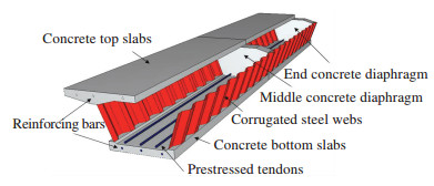
The diagrammatic sketch of theprestressed concrete box-girder with corrugated steel webs is shown in Fig. 1.
|
Figure 1 Diagrammatic sketch of the prestressed concrete compositebox-girder bridge with corrugated steel web |
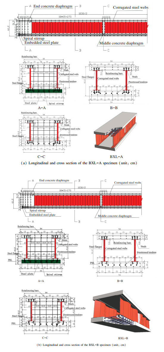
The shear connectors used to bond with the concrete top/ bottom slab and corrugated steel webs are one of the key factors that ensures the prestressed concrete composite box-girder with corrugated steel webs successfully works.At present, two types of shear connectors, PBL and studs (as shown in Fig. 2), are widely used in prestressed concrete composite box-girder bridges with corrugated steel webs.The two shear connectors may differently impact the structural performance of the prestressed concrete composite box-girder with corrugated steel, and so far the impacts are not yet clearly understood.So the two types of shear connectors, PBL and studs, were also studied by test methods in this paper.
|
Figure 2 Longitudinal and cross section of specimens BXL-A and BXL-B |
2 Test 2.1 Test Specimens
Table 1 is the summary of test specimens researched in this paper, among which were two prestressed concrete box-girders with corrugated webs, named BXL-A and BXL-B, which were tested to evaluate the impact of a different type of shear connector on structural performance.
| Table 1 Test specimens |
Fig. 2 shows the two specimens' profiles, dimen-sions, and sectional details, in which the BXL-A specimen uses studs shear connectors, and BXL-B specimen uses PBL shear connectors.
The two specimens were 10 300 mm long and 612 mm high.Both ends of the concrete diaphragms were 500 mm thick, and there were two middle concrete diaphragms of 100 mm thickness, which were 3 200 mm from each end of the specimen.The concrete top and bottom slab were 80 mm and 120 mm thick, respectively.
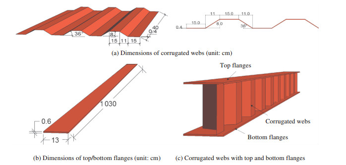
The corrugated webs of the specimens BXL-A and BXL-B were 400 mm high and 4 mm thick.Dimensions of the corrugated webs are as follows:wave height is 80 mm, and wave height angle is 36°.The top/ bottom flanges were 6 mm thick and 130 mm width. Fig. 3 shows the dimensions of corrugated webs and the top and bottom flanges.
|
Figure 3 Corrugated webs and top/bottom flanges |
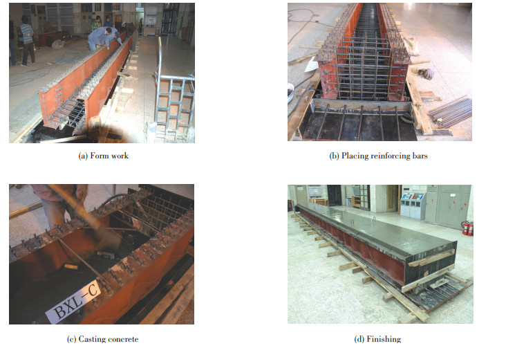
When the top and bottom flanges and the corrugated webs were finished, they were welded together (as shown in Fig. 4).The entire manufacturing process of test specimens is shown in Fig. 5(a) to (d).

|
Figure 4 Corrugated webs welded top and bottom flanges |
|
Figure 5 Fabrication of the specimen |
Shear studs which are 10 mm in diameter and have a 20 mm stud head diameter, were placed with a 100 mm spacing on the steel flanges.Their tensile strength is 440 MPa.
As shown in Fig. 2, the composite sections of the specimens BXL-A, and BXL-B are box-shaped, whose concrete top slab was 80 mm thick and 940 mm wide.The box-girder section was 612 mm high.In the box-girder top slabs, D16 longitudinal reinforcing bars, which were placed in double layers, were at 130 mm or 150 mm spacing.In D13 bars were placed in a perpendicular direction using 500 mm spacing.The tendons, 15.2 mm in diameter, were placed with 120 mm spacing in the bottom of the concrete slab.
Table 2 is the concrete mix proportion, and Table 3 is material test results.
| Table 2 Concrete mixture proportion |
| Table 3 Material test results |
2.2 Loading and Measurements
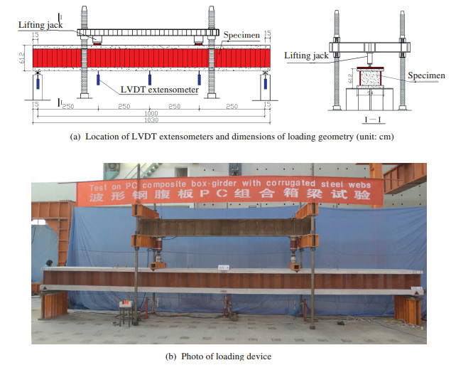
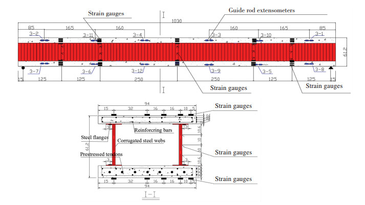
As shown in Fig. 6, the test beam which was simply supported is a 1 000 cm span length.Their deflections may be gained by five LVDT extensometers installed under the specimens, which were located at the two end supports, the two point concentrated load points, and at the center of the specimens.The relative slip, between the steel flange and the concrete top/bottom slabs, may be measured by the guide rod extensometers, which were placed at both ends of the test beam.The strains were monitored by the strain gauges which were installed on the surface of the top and bottom of the concrete slab, the top and bottom flanges and the corrugated webs, as shown in Fig. 7.
|
Figure 6 Loading device |
|
Figure 7 Location of the guide rod extensometers and strain gauges on specimens BXL-A and BXL-B (unit:cm) |
3 Test Process
The same design prestressing, which was 3.0 MPa, was introduced into the concrete bottom slab of the specimens BXL-A, and BXL-B.To ensure that the prestressing was evenly distributed along the tendon, the prestressing was introduced twice into specimens, and half of the prestressing (approximately 1.5 MPa) was introduced each time.After the first stage was finished, there was a five minute break, and then the second stage begun to introduce the design prestressing.The design prestressing was effective prestressing considering the instantaneous loss.
After the completion of the prestressing work, the composite girder was fixed onto an experimental bench.When all preparations for test were finished, the loading was initiated.
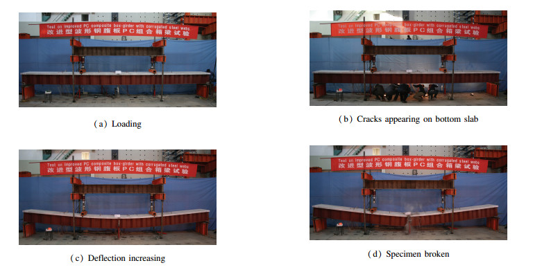
Fig. 8 shows the test process of the BXL-A specimen.
|
Figure 8 Test process of the BXL-A specimen |
4 Test Analyses
In order to research the impact of the different shear connectors onstructure performances, the two specimens were fabricated with the same dimensions, materials, and environmental conditions, and tests were conducted on the BXL-A specimen with shear studs and the BXL-B specimen with shear connectors PBL.
The specimens' end-slips, between the concrete top and bottom slabs and the steel flange, were monitored by the guide rod extensometers installed at both ends of the specimens.The end slips of the BXL-A and BXL-B were initiated when the loads were 584 and 690 kN, and when BXL-A and BXL-B failed, their end slips reached the biggest values, which were 0.8 and 0.3 mm, respectively.Therefore, the slip values were too small to impact the two test specimens' normal work.In addition, it was observed during the test that the reason for the two test specimens' failure was that the concrete top slabs were crushed rather than excessive slips between the concrete top and bottom slabs and the steel flange.So, it can be confirmed that both PBL and studs shear connectors have perfect anti-slip properties, the specimens cannot fail because of the two shear connectors' worse anti-slip performance, and both of them can ensure that a prestressed concrete composite box-girder with corrugated steel webs works normally.
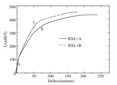
4.1 Load-Displacement ResponsesThe load-displacement curves of the two test beams are shown in the Fig. 9.
|
Figure 9 Load-deflection curves |
Their loads-displacement curves were continually increased with two obvious turning points A and B (or C).The turning points A indicated that the concrete bottom slab had cracked, and the turning points B (or C) indicated that the tension reinforcement in the concrete bottom slab had yielded.Therefore, the specimens BXL-A, and BXL-B showed perfect nonlinear behavior in their overall loading history.
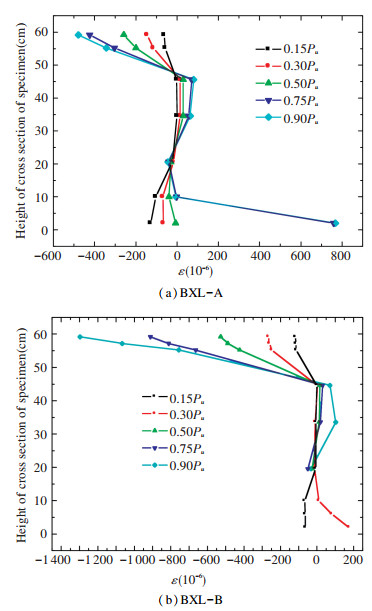
4.2 Strains Distribution on the Cross Section of the Corrugated Webs 4.2.1 Axial strains distributions on the cross section of the corrugated websFig. 10 shows the axial strains distributed on the cross section of the specimens BXL-A, and BXL-B, which were monitored by strain gauges attached on the mid-span section of specimens under the different loads, which were 0.15Pu, 0.30Pu, 0.50Pu, 0.75Pu and 0.90Pu.
|
Figure 10 Axial strain distributions |
The axial strains on the corrugated webs were minimally changed and almost zero, while the axial strains on the top/bottom slabs were larger and increased with the load increasing (The phenomenon which the strains on the corrugated webs were very small under the loads is described as the accordion effect[16-18]).Therefore, the conclusion can be drawn that the flexural stiffness of the concrete top and bottom slabs was much greater than that of the corrugated webs, which was almost zero.The bending moments were mainly borne by the concrete top and bottom slabs rather than by corrugated webs.
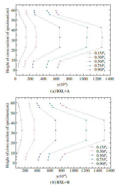
4.2.2 Shearing strain distributions on the corrugated websFig. 11 shows the shearing strains distributions on the cross section of the specimens, which were measured by strains gauges attached on the mid-span section of specimens during the different loads, which were 0.15Pu, 0.30Pu, 0.50Pu, 0.75Pu and 0.90Pu. The shearing strains on the top/bottom slabs were smaller, while the shearing strains on the corrugated webs were larger continued increasing as the load increased.It can be shown in Fig. 16 that the shearing stiffness on the corrugated webs was far greater than that on the top and bottom slabs.Therefore, the shear force were mainly borne by the corrugated webs more than by the top and bottom slabs.
|
Figure 11 Shearing strains distributions |
|
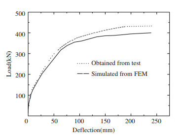
Figure 16 Comparison of the results simulated from FEM and obtained from test |
4.3 Impact of Shear Connectors on the Structure Performances 4.3.1 Impact of shear connectors on the ultimate bearing capacities
The ultimate load of the BXL-B specimen was 480 kN, and the BXL-A specimen was 412 kN.The value of BXL-B was 16.5% larger than one of the BXL-A.This illustrates that, compared to studs shear connectors, PBL shear connectors can improve the ultimate bearing capacities of prestressed concrete composite box-girders with corrugated steel webs.The reason is that the two steel flanges acted as tension reinforcements.
4.3.2 Impact of shear connectors on the flexural stiffnessFig. 9 showed that before the concrete bottom cracked, the curves of BXL-A and BXL-B almost coincided, but after the concrete bottom cracked, the deflection of BXL-A was greater than that of BXL-B.
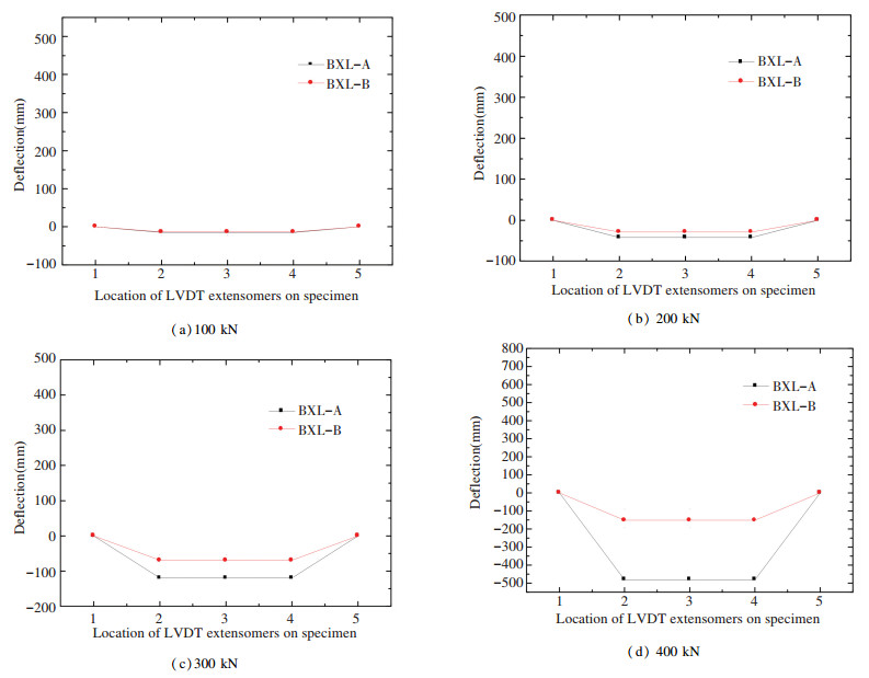
Fig. 12 showed the deflections in the specimens BXL-A, and BXL-B under the various loads 100, 200, 300, and 400 kN.When the loads were 100 and 200 kN, the deflections in specimens BXL-A, and BXL-B were similar.But when the load was 300 and 400 kN, the deflections of the BXL-A were far larger than that of the BXL-B.
|
Figure 12 Deflections in the specimens under the various loads |
In addition, the deflection values of specimens BXL-A, and BXL-B are shown in Table 4, where Py is yield load, Pu is ultimate load, δy is the deflection value caused by yield load, δu is the deflection value caused by ultimate load, δu/δy is ductility factor.
| Table 4 Deflection value of specimens |
Table 4 shows that the deflection values caused by the yield load, on the specimens BXL-A and BXL-B, were 58 mm and 60 mm, and the deflection values caused by the ultimate load were 248 and 160 mm, and their ductility factors were 4.28 and 2.67, respectively.These illustrate that, in the elastic phase, the flexural stiffness of the girder was negligibly impacted by adopting the PBL or studs shear connectors, but in the plastic phase, the flexural stiffness of the girder was improved by adopting the PBL shear connectors.
4.3.3 Impact of shear connectors on the crack resistance propertyIf the concrete slab had cracked and the cracks had been wide enough, the water vapor, carbon dioxide and oxygen, etc., in the air would have been prone to contact the tense reinforcement in the concrete slabs and would have caused the tense reinforcement to be corroded.In order to avoid tense reinforcement corrosion, it is important to improve the crack resistance property of the prestressed concrete composite box-girders with corrugated steel webs.
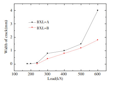
The crack load of the specimen BXL-A with studsshear connector was 119 kN, while the specimen BXL-B with PBL shear connector was 138 kN.Compare to BXL-A, the crack load of BXL-B was increased by 16%.
Fig. 13 showed the width of the major cracks on the concrete bottom of the specimens BXL-A, and BXL-B with the load history.The width of the major cracks in the BXL-A specimen was considerably increased with load history, but the major cracks in the BXL-B specimen were eventually increased.In addition, the wide value of major cracks of the BXL-A specimen was always bigger than that of the specimen BXL-B with this load history.
|
Figure 13 Width of the major cracks with the load history |
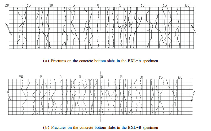
Fig. 14 shows that the cracks were distributed on the concrete bottom slabs in the specimens BXL-A, and BXL-B.
|
Figure 14 Fractures on the concrete bottom slabs |
All these are illustrated that the crack resistance property of the specimen with the PBL shear connectors is superior to that of specimen with the studs shear connectors.
4.3.4 Impact of the different shear connectors on the efficiency of prestressing introducedIn order to research the impact of the different shears connectors on the efficiency of prestressing introduced in the prestressed concrete composite box-girders with corrugated steel webs, the BXL-A specimen with studs shear connectors and the BXL-B specimen with PBL shear connectors were prestressed under the same conditions, including the same anchor system, the same strands and the same load time and speed, etc.In the course of experiment, the same effective prestressing, which was 3 MPa, was introduced into the concrete bottom slabs of the specimens BXL-A and BXL-B.
The tensioned control stress on the end of the specimens BXL-A and BXL-B may be measured by the load cells laid on the specimen ends.The values of tensioned control stress are showed in the Table 5.After the effective prestressing value and the tensioned control stress value were obtained, the efficiency of the prestressing introduced into the concrete bottom slabs was easily calculated by the formula(1).
| $ \zeta = \frac{{{\sigma _{\rm{y}}}}}{{{\sigma _{\rm{c}}}}} $ | (1) |
| Table 5 Efficiency of prestressing introduced into the specimens |
where ζ is the efficiency of the prestressing introduced into the concrete bottom slabs; σy is the effective prestressing; σc is the tensioned control stress.
Table 5 shows the efficiency of prestressing introduced into the specimens BXL-A and BXL-B were 93.75% and 88.24%, respectively.Compared to BXL-A, the efficiency of the prestressing introduced into the concrete bottom slab of BXL-B was decreased by 5.88%.Therefore, relative to the studs shear connector, the PBL shear connector reduced the efficiency of prestressing introduced in the prestressed concrete composite box-girders with corrugated steel webs.
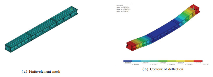
5 Finite Element Simulation AnalysisIn the study, the finite element analysis program ANSYS was adopted to simulate flexural behavior of the BXL-A specimen.
Elements were selected by the follows means:
SOLID65 element, which is the eight-node 3-D Reinforced Concrete Solid element, was used in order to simulate the concrete top and bottom slabs.To analyze the nonlinear flexural, the constitutive equation for concrete, which was proposed by Hongnestad, was adopted.The uniaxial stress-strain relationship of the nonlinear flexural is the Hongnestad model, which is incorporated into the finite-element (FE) model, which was finished by the Multilinear Isotropic Hardening (MISO) option.Before the concrete cracks, the tensile stress-strain is linear elastic.The William and Warnke criterion was uitilized as the concrete failure criterion for the nonlinear flexural analysis.
The SOLID45 element was adopted for simulating themiddle and end concrete diaphragms, and the concrete cracking or crushing of the middle and end diaphragms were not taken into consideration.
The SHELL181 element was applied for simulating the corrugated steel webs, steel flanges, and the bottom steel plate of BXL-D.
The LINK8 element, which is the 3D two-node spar element, was adopted for simulating the reinforcing bars and prestressed tendons.
Fig. 15 shows the finite-element mesh and the simulation result of the BXL-A specimen.Fig. 16 shows a comparison of the simulation results of the BXL-A specimen to the test results.The initial flexural stiffness obtained from the test is almost the same as the one estimated by the FE simulation, but after the concrete bottom slabs cracked, the flexural stiffness estimated by the FE simulation was greater than that of obtained from the test.However, their overall flexural responses were similar.Also, the FE results were very close to the test results.
|
Figure 15 Finite element mesh and the simulation result of the BXL-A specimen |
6 Conclusions
1) The ultimate bearing capacities of prestressed concrete composite box-girder with corrugated steel webs with the PBL shear connectors was greater than the one with the studs shear connectors.The ultimate bearing capacities of prestressed concrete composite box-girder with corrugated steel webs can be improved when the PBL shear connectors are adopted.
2) As for flexural stiffness, before the concrete bottom slab cracked, the flexural stiffness of the girder with the PBL shear connectors was similar to the girder with the studs shear connectors.But after the concrete bottom cracked, the flexural stiffness of the girder with the PBL shear connectors was observably larger than the girder with the studs shear connectors.
3) The girder with the PBL shear connectors, in the crack resistance property, was superior to the one with the studs shear connectors.
4) The efficiency of prestressing introduced into the girder with the PBL shear connector was lower than the one introduced into the girder with the studs shear connector.Compared to the studs shear connector, The PBL shear connectors reduced the efficiency of prestressing introduced into the prestressed concrete composite box-girders with corrugated steel webs.
| [1] |
Ding Yong, Jiang Kebin, Liu Yawen. Nonlinear analysis for PC box-girder with corrugated steel webs under pure torsion. Thin-Walled Structures, 2012, 51: 167-173. DOI:10.1016/j.tws.2011.10.013 ( 0) 0)
|
| [2] |
Elgaaly M, Hamilton R W, Seshadri A. Shear strength of beams with corrugated webs. Journal of Structural Engineering, ASCE, 1996, 122(4): 390-398. DOI:10.1061/(ASCE)0733-9445(1996)122:4(390) ( 0) 0)
|
| [3] |
Elgaaly M. Girders with corrugated webs under partial compressive edge loading. American Society of Civil Engineers, Structural Journal, 1997, 108(6): 270-298. ( 0) 0)
|
| [4] |
Huang Ling, Hikosaka H, Komine K. Simulation of accordion effect in corrugated steel web with concrete flanges. Computers and Structures, 2004, 82: 2061-2069. DOI:10.1016/j.compstruc.2003.07.010 ( 0) 0)
|
| [5] |
Yuan Aimin, Dai Hang, Dong Yuli. The latest study development in composite bridgewith corrugated steel webs. Journal of Qingdao Technological University, 2008, 29(4): 30-35. ( 0) 0)
|
| [6] |
Li Chao, Lu Xiaoru, Wan Shui, et al. Construction of the PC box-girder with the corrugated steel webs of Pohe Bridge. Journal of Heilongjiang Institute of Technology, 2006, 20(2): 19-22. ( 0) 0)
|
| [7] |
Jung K H, Kim K S, Sim C W, et al. Verification of incremental launching construction safety for the Ilsun Bridge, the world's longest and widest prestressed concrete box girder with corrugated steel web section. J Bridge Eng, 2011, 3(5): 453-460. ( 0) 0)
|
| [8] |
Lee D H, Jae O Y, Kang H, et al. Structural performance of prestressed composite girders with corrugated steel plate webs. Journal of Constructional Steel Research, 2015, 104: 9-21. DOI:10.1016/j.jcsr.2014.09.014 ( 0) 0)
|
| [9] |
Kim K S, Lee D H, Choi S M, et al. Flexural behavior of prestressed composite beams with corrugated webs:Part Ⅰ.Development and analysis. Comp Part B Eng, 2011, 42: 1603-1616. DOI:10.1016/j.compositesb.2011.04.020 ( 0) 0)
|
| [10] |
Kim K S, Lee D H. Flexural behavior of prestressed composite beams with corrugated webs:Part Ⅱ.Experiments and verification. Comp Part B Eng, 2011, 42: 1617-1629. DOI:10.1016/j.compositesb.2011.04.019 ( 0) 0)
|
| [11] |
Huang Qingwei, Chen Baochun. Trial design for concrete arch bridge with corrugated steel web. Journal of Harbin Institute of Technology (New Serials), 2016, 23(6): 16-24. ( 0) 0)
|
| [12] |
Wang Chunsheng, Nie Jianguo. State of the art of fatigue tests and fatigue performance of composite girders with corrugated steel webs. Journal of Harbin Institute of Technology (New Serials), 2005, 37(8): 222-225. ( 0) 0)
|
| [13] |
Anami K, Sause R, Abbss H H. Fatigue of web-flange weld of corrugated web girders:1.Influence of web corrugation geometry and flange geometry on web-flange weld toe stresses. International Journal of Fatigue, 2005, 27(3): 373-381. ( 0) 0)
|
| [14] |
Anami K, Sause R. Fatigue of web-flange weld of corrugated web girders:2.Analytical evolution of fatigue strength of corrugation web-flange wield. International Journal of Fatigue, 2005, 27(3): 383-393. ( 0) 0)
|
| [15] |
Ahn J H, Lee C G, Won J H, et al. Shear resistance of the perfobond-rib shear connector depending on concrete strength and rib arrangement. Journal of Constructional Steel Research, 2010, 66(10): 1295-1307. DOI:10.1016/j.jcsr.2010.04.008 ( 0) 0)
|
| [16] |
Lbrabim S A, EI-Dakhakhni W W, Elgaaly M. Fatigue of corrugated-web plate:Analytical study. Journal of Structural Engineering, ASCE, 2006, 132(9): 1381-1392. DOI:10.1061/(ASCE)0733-9445(2006)132:9(1381) ( 0) 0)
|
| [17] |
Robert G V, Hassan H A, Richard S. Shear behavior of corrugated web bridgegirders. Journal of Structural, 2006, 132(2): 195-203. DOI:10.1061/(ASCE)0733-9445(2006)132:2(195) ( 0) 0)
|
| [18] |
Basher M, Shanmugam N E, Khalim A. Horizontally curved composite plate girders with trapezoidally corrugated webs. Journal of Constructional Steel Research, 2011, 67(6): 947-956. DOI:10.1016/j.jcsr.2011.01.015 ( 0) 0)
|
 2018, Vol. 25


