2. Guangdong Province Research Center of Electronic Information Products Reliability and Environment Engineering Technology, Guangzhou 510610, China;
3. Guangdong Provincial Key Laboratory of Electronic Information Products Reliability Technology, Guangzhou 510610, China;
4. Guangzhou Province Key Laboratory of Electronic Information Products Reliability and Environment Engineering Technology, Guangzhou 510610, China
There are increasing requirements for precision pointing and high image resolution for current and future space optical payloads.However, vibration disturbances generated by mechanical equipment onboard spacecrafts (such as reaction/momentum wheel assemblies, cryo-coolers, thrusters, solar array drive mechanisms, and other motion devices) can seriously degrade the image quality of space optical payloads[1].To solve this problem, vibration isolators are usually inserted in the transmission path between the source of the disturbance and the payload[2].
Many vibration isolation systems have been proposed to help high-precision payloads avoid the impact of vibrations in onboard spacecraft.Typical examples are the Hubble Space Telescope[3] and X-Ray Astrophysics Facility[4], which apply passive isolators to achieve their science missions.As the next generation space telescope, the James Webb Space Telescope with a 6.5 m aperture requires that the stability of the image quality should change by no more than 2% between images taken over a 24 h period.To satisfy this requirement, an isolation system consisting of four beams with embedded viscoelastic damping layers was adopted[5].The Air Force Institute of Technology researchers designed a passive VIS for the Space Chromotomography Experiment, which was an imaging chromotomographic spectrometer designed for flight on the International Space Station and was sensitive to jitter caused by vibrations[6].To mitigate the vibration disturbances caused by the reaction wheel assembly, Kamesh et al.[7-8] developed a low-frequency flexible VIS to isolate a disturbance source from the precision payloads in a spacecraft.
With the development of smart sensors, actuators and microprocessors, active vibration suppression is becoming an another alternative for vibration isolation.For example, the vibration isolation and suppression system was designed to isolate a precision payload from vibrations onboard the spacecraft [9].The Air Force Research Laboratory Space Vehicle Directorate cooperated with Honeywell Defense and Space to develop the Miniature VIS Ⅱ[10].The Terrestrial Planet Finder Coronagraph (TPFC), which is a visible-light coronagraph to detect planets, must achieve a contrast ratio stability of 2e-11.A precision pointing and VIS for the TPFC was designed[11].Preumont and de Marneffe et al.[12-13] proposed a six-axis Stewart active isolator for space applications.Although active vibration isolation has received increased attention, passive vibration isolation is frequently the first step to be taken to remedy vibration issues onboard a spacecraft because of its reliability, low cost, and effectiveness[3-5, 8]. Moreover, the effect of active isolation is limited by the sensor characteristics[14].Therefore, many active vibration isolators for space applications combine passive and active isolation.In the event of a power failure in orbit, the VIS can gracefully degrade to its passive isolation performance.For example, Honeywell Inc.has designed a series of D-Struts®[15-19], which use a bellows system with a viscous damping fluid.Its effectiveness was sufficiently proved by the Hubble reaction wheel isolation system[3].This isolator has been redesigned to combine passive and active vibration isolation systems, such as the Isolation, Pointing and Suppression system[20].The details of these active/passive vibration isolation systems have been introduced in Refs.[9-10, 18, 21-23].
In this paper, a new passive vibration isolator for space optical payload in orbit is proposed.This proposed isolator consists of double-deck leaf springs with in-filling silicon rubber.This design can reduce the stress on the leaf springs and increase the damping, making it suitable for the vibration attenuation of sensitive instruments in orbit.The equivalent stiffness model of the isolator and the dynamic model of the VIS based on the bipod configuration were derived.The transmissibility of the VIS was calculated with the proposed analysis approach, which was applicable to analyzing viscoelastic material (VEM).An experimental setup consisting of a dummy payload floating on air-bearings was adopted to demonstrate the effectiveness of the isolator and the analysis approach.
This paper includes following aspects:in Section 2, the structure of the vibration isolator is described in detail, and its stiffness model and static load test are presented.Section 3 addresses the vibration attenuation test system.Section 4 presents the experimental apparatus and results.Concluding remarks on the vibration isolator are presented in Section 5.
2 Vibration Isolator 2.1 Structural DesignThe detailed structure of the vibration isolator is depicted in Fig. 1.It consists of a flexure, two elastic damping rings, connecting rods, and flanges.The elastic damping ring is composed of double-deck leaf springs and connecting elements.The double-deck leaf springs are fixed to the connecting elements with bolts and in-filled with silicon rubber.The flexure has a high axial and bending rigidity but a low torsional rigidity.When a loading force is applied to the vibration isolator, the leaf springs of the isolator deform to provide the stiffness, and the silicon rubber is compressed and sheared to provide the damping.The stiffness and damping of the isolator can be adjusted by changing its geometric parameters, such as the length, width, and thickness of the leaf spring and silicon rubber.Hence, it can be suitable for different payloads with different dimensions, masses and moments of inertial.Different arrangement styles consisting of multiple isolators can be adopted to achieve multi-axis vibration isolation.The material of the leaf springs is 65 Mn which is the spring steel, while the other component material of the isolator is titanium.Table 1 shows the detailed geometric properties of the isolator.
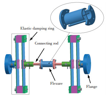
|
Figure 1 Structure of the vibration isolator |
| Table 1 Geometric properties of the vibration isolator |
2.2 Stiffness Model of the Vibration Isolator
This section focuses on the stiffness analysis of the vibration isolator.When an axial force (along the y-axis) is applied to the isolator, the leaf springs deform along the y-axis. The axial stiffness coefficient of the isolator may be calculated using Hooke's Law.However, for the test and calculation of stiffness of the isolator in other directions, it is not suitable to use Hooke's Law directly, because the leaf springs incur longitudinal extension and distortion when a transverse force (along the x-axis) or lateral force (along the z-axis) is applied to one end of the isolator, as shown in Fig. 2.
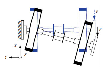
|
Figure 2 Deformation diagram of a single vibration isolator |
A solution to this problem is proposed, and is depicted in Fig. 3.As shown in Fig. 3, two identical isolators are connected to each other at one end and the other ends are fixed to a base.A transverse (lateral force) is loaded to the connection point, the displacement of the connection point along the direction of the force is then measured, and the transverse (lateral) stiffness coefficient can be calculated using Hooke's Law.

|
Figure 3 Deformation diagram of double vibration isolators |
According to the distortion of the leaf springs shown in Fig. 3, a stiffness model can be established, which describes the stiffness characteristic of the isolator using an axial stiffness Ky (along the y-axis), a rotational stiffness Kβ (around the z-axis), and a twisting stiffness Kα (around the x-axis). The center of the elastic damping ring is the rotation center point.The advantages of this stiffness model are that the transverse and lateral stiffness coefficients are only concerned with the elastic damping ring.
When a unit force F is applied to the connection of the two isolators, the displacement s can be calculated. The rotation angle β of the isolator around the center of the elastic damping ring can be described as:
| $ \beta = \arcsin \frac{s}{L} $ | (1) |
The moment M about the center of the elastic damping Ring 1 can be written as:
| $ M = F \cdot a $ | (2) |
Assuming a linear relationship between moment M and rotation angle β, the rotational stiffness Kβ of a single elastic damping ring can be described as:
| $ {K_\beta } = \frac{M}{\beta } = \frac{{F \cdot a}}{{\arcsin \left( {s/L} \right)}} $ | (3) |
Because the elastic damping Ring 2 is identical to Ring 1, the rotational stiffness of Ring 2 also has the value Kβ. Similarly, the twisting stiffness Kα of the isolator can be obtained.
2.3 Static Load Test of the Vibration IsolatorA static load deflection test was utilized to measure the axial, rotational, and twisting stiffness coefficients of this isolator.The measurement system consisted of the auxiliary device, cable, and the pull and pressure tester, as shown in Fig. 4.The auxiliary device was used to fix the vibration isolators.Because the isolators were very soft, a cable was used to suspend them.The pull and pressure tester was used to measure force and displacement.The experimental results are shown in Fig. 5.

|
Figure 4 Illustration of the stiffness measurement system |
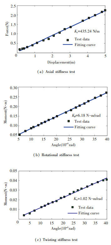
|
Figure 5 Experimental results and fitting curves of the static load test |
Table 2 shows the comparison of the stiffness coefficients of the isolator obtained using the finite element method (FEM) and experimental method.From Table 2, it can be observed that the FEM analysis results coincided well with the experimental data.The minimum relative error was 0.02%, while the maximum relative error was 4.21%.
| Table 2 Stiffness coefficients of the isolator |
3 Vibration Attenuation Test System
As outlined earlier, vibration isolators arranged in a suitable configuration can provide multi-axis vibration isolation, such as in the vibration isolation and suppression system[9] and Miniature VIS Ⅱ[10].They all used six hybrid isolation struts in a hexapod configuration to isolate a precision payload from spacecraft born disturbances.This hexapod contained three bipods, which consisted of two isolators.In this study, a simplified VIS in a bipod configuration was used to research the isolation characteristics of the isolator, which are depicted in Fig. 6.The optical payload was replaced by a dummy payload.As shown in Fig. 6, two air feet were placed under the dummy payload to offset the gravity on the payload.

|
Figure 6 Vibration isolators in bipod configuration |
3.1 Dynamic Model
The dynamic model diagrammatic drawin of the VIS is shown in Fig. 7 and consists of the vibration isolators arranged in a V-shape with the angle between them denoted by 2θ. The lines AE and BF denote the isolators, and intersect at G. The coordinate systems G-XYZ, A-X1′Y1′Z1′, and B-X2′Y2′Z2′ are fixed to points G, A, and B, respectively.As a planar system, the dummy payload has three degrees of freedom (DOFs), i.e., two translational DOFs and one rotational DOF.The motion of the dummy payload can be decomposed into two mutually orthogonal translational motions and one rotational motion.The translational component along the x-axis is denoted by x, the translational component along the y-axis is denoted by y, and the rotation angle component around the z-axis is denoted by β.
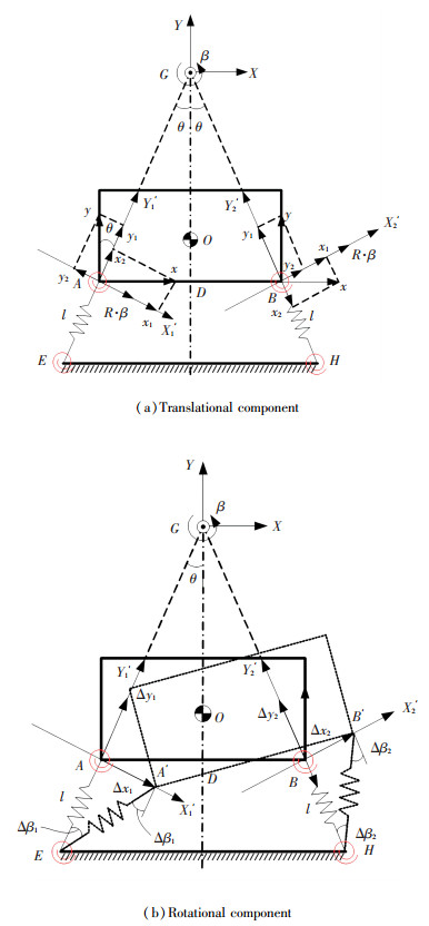
|
Figure 7 Diagrammatic drawin of the VIS |
Because the oscillation of the dummy payload is small, the orientations of coordinate systems A-X1′Y1′Z1′, B-X2′Y2′Z2′ may be considered to be unchanging.The translational component of point A along the X1′-axis under the coordinate system A-X1′Y1′Z1′ can be described as:
| $ \Delta {x_1} = {x_1} + R \cdot \beta - {y_2} = x\cos \theta - y\sin \theta + R \cdot \beta $ | (4) |
The translational component of point A along the Yj′-axis under the coordinate system A-X1′Y1′Z1′ can be described as:
| $ \Delta {y_1} = {y_1} + {x_2} = y\cos \theta + x\sin \theta $ | (5) |
Similarly, the translational component of point B along the X2′-axis under the coordinate system B-X2′Y2′Z2′ can be described as:
| $ \Delta {x_2} = {x_1} + {y_2} + R \cdot \beta = x\cos \theta + y\sin \theta + R \cdot \beta $ | (6) |
The translational component of point B along the Y2′-axis under the coordinate system B-X2′Y2′Z2′ can be described as:
| $ \Delta {y_2} = {y_1} - {x_2} = y\cos \theta - x\sin \theta $ | (7) |
The rotational component of line AE around the point E can be described as:
| $ \Delta {\beta _1} = \frac{{\Delta {x_1}}}{l} = \frac{1}{l}\left( {x\cos \theta - y\sin \theta + R \cdot \beta } \right) $ | (8) |
Similarly, the rotational component of line BF around the point F can be described as:
| $ \Delta {\beta _2} = \frac{{\Delta {x_2}}}{l} = \frac{1}{l}\left( {x\cos \theta + y\sin \theta + R \cdot \beta } \right) $ | (9) |
The Lagrange equation for the VIS can be written as:
| $ \frac{{\rm{d}}}{{{\rm{d}}t}}\left( {\frac{{\partial \left( {T - V} \right)}}{{\partial {{\dot q}_j}}}} \right) - \frac{{\partial \left( {T - V} \right)}}{{\partial {q_j}}} = 0, j = 1, 2, \cdots, N $ | (10) |
where qj is the generalized coordinate,
| $ T = \frac{1}{2}m{{\dot x}^2} + \frac{1}{2}m{{\dot y}^2} + m\rho \; \dot\beta \dot x + \frac{1}{2}J{{\dot \beta }^2} $ | (11) |
| $ \begin{array}{l} V = \frac{1}{2}{K_y}{\left( {\Delta {y_1}} \right)^2} + \frac{1}{2}{K_y}{\left( {\Delta {y_2}} \right)^2} + \\ \;\;2 \cdot \frac{1}{2}{K_\beta }{\left( {\Delta {\beta _1}} \right)^2} + 2 \cdot \frac{1}{2}{K_\beta }{\left( {\Delta {\beta _2}} \right)^2} = \\ \;\;\;\;\frac{1}{2}{K_y}\left[{{{\left( {y\cos \theta + x\sin \theta } \right)}^2} + } \right.\\ \;\;\;\;\left. {{{\left( {y\cos \theta-x\sin \theta } \right)}^2}} \right] + \\ \;\;\;\;\;{K_\beta }\left[{\frac{1}{{{l^2}}}{{\left( {x\cos \theta-y\sin \theta + R\beta } \right)}^2} + } \right.\\ \;\;\;\;\;\;\left. {\frac{1}{{{l^2}}}{{\left( {x\cos \theta + y\sin \theta + R\beta } \right)}^2}} \right] \end{array} $ | (12) |
where ρ is the length of line OG, m and J are the mass and moment inertia of the dummy payload, respectively.
Substituting Eqs.(11) and (12) into Eq.(10), the first term on the left-hand side of Eq.(10) can be written as:
| $ \frac{{\partial \left( {T - V} \right)}}{{\partial \dot x}} = \frac{1}{2}m \cdot 2\dot x + m\rho \dot \beta = m\dot x + m\rho \dot \beta $ | (13) |
| $ \frac{{\partial \left( {T - V} \right)}}{{\partial \dot y}} = \frac{1}{2}m \cdot 2\dot y = m\dot y $ | (14) |
| $ \frac{{\partial \left( {T - V} \right)}}{{\partial \dot \beta }} = \frac{1}{2}J \cdot 2\dot \beta + m\rho \dot x = J\dot \beta + m\rho \dot x $ | (15) |
Similarly, the second termon the right-hand side of Eq.(10) can be written as:
| $ \begin{array}{l} \frac{{\partial \left( {T - V} \right)}}{{\partial x}} = - \frac{1}{2}{K_y}\left[{2\left( {y\cos \theta + x\sin \theta } \right) \cdot \sin \theta + } \right.\\ \;\;\;\;\;\;\left. {2\left( {y\cos \theta-x\sin \theta } \right)\left( {-\sin \theta } \right)} \right] - \frac{{{K_\beta }}}{{{L^2}}}\left[{2\left( {x\cos \theta-} \right.} \right.\\ \;\;\;\;\;\;\left. {y\sin \theta + R \cdot \beta } \right)\cos \theta + 2\left( {x\cos \theta + y\sin \theta + } \right.\\ \;\;\;\;\;\;\left. {\left. {R \cdot \beta } \right)\cos \theta } \right] = - \left( {2{K_y}{{\sin }^2}\theta + \frac{4}{{{l^2}}}{K_\beta }{{\cos }^2}\theta } \right)x - \\ \;\;\;\;\;\;\frac{4}{{{l^2}}}{K_\beta } \cdot R \cdot \beta \cdot \cos \theta \end{array} $ | (16) |
| $ \begin{array}{l} \frac{{\partial \left( {T - V} \right)}}{{\partial y}} = - \frac{1}{2}{K_y}\left[{2\left( {y\cos \theta + x\sin \theta } \right)\cos \theta + } \right.\\ \;\;\;\;\;\;\left. {2\left( {y\cos \theta-x\sin \theta } \right)\cos \theta } \right] - \frac{1}{{{L^2}}}{K_\beta }\left[{2\left( {x\cos \theta-} \right.} \right.\\ \;\;\;\;\;\;\left. {y\sin \theta + R \cdot \beta } \right)\left( {-\sin \theta } \right) + 2\left( {x\cos \theta + y\sin \theta + } \right.\\ \;\;\;\;\;\;\left. {\left. {R \cdot \beta } \right)} \right]\sin \theta = - \left( {2{K_y}{{\cos }^2}\theta + \frac{4}{{{l^2}}}{K_\beta }{{\cos }^2}\theta } \right)y \end{array} $ | (17) |
| $ \begin{array}{l} \frac{{\partial \left( {T - V} \right)}}{{\partial \beta }} = - \frac{{{K_\beta }}}{{{L^2}}}\left[{2\left( {x\cos \theta-y\sin \theta + R \cdot \beta } \right)R + } \right.\\ \;\;\;\;\;\;\left. {2\left( {x\cos \theta + y\sin \theta + R \cdot \beta } \right)} \right] = - \frac{4}{{{l^2}}}{K_\beta } \cdot R \cdot x \cdot \\ \;\;\;\;\;\;\cos \theta - \frac{4}{{{l^2}}}{K_\beta } \cdot {R^2} \end{array} $ | (18) |
Substituting Eqs.(13)-(18) into Eq.(10) yields:
| $ \left\{ \begin{array}{l} m\ddot x + m\rho \ddot \beta + \left( {2{K_y}{{\sin }^2}\theta + \frac{4}{{{l^2}}}{K_\beta }{{\cos }^2}\theta } \right)x + \\ \;\;\;\;\;\;\;\frac{4}{{{l^2}}}{K_\beta } \cdot R \cdot \beta \cdot \cos \theta = 0\\ m\ddot y + \left( {2{K_y}{{\cos }^2}\theta + \frac{4}{{{l^2}}}{K_\beta }{{\cos }^2}\theta } \right)y = 0\\ J\ddot \varphi + m\rho \ddot x + \frac{4}{{{l^2}}}{K_\beta } \cdot R \cdot x \cdot \cos \theta + \\ \;\;\;\;\;\;\;\frac{4}{{{l^2}}}{K_\beta } \cdot {R^2} \cdot \beta = 0 \end{array} \right. $ | (19) |
This equation can be written in a matrix form as:
| $ {\mathit{\boldsymbol{M}}_p}\mathit{\boldsymbol{\ddot q}} + {\mathit{\boldsymbol{K}}_P}\mathit{\boldsymbol{q}} = 0 $ | (20) |
where Mp is the 3 × 3 mass matrix, Kp the 3 × 3 matrix of the generalized stiffness,
| $ {\mathit{\boldsymbol{M}}_p} = \left[{\begin{array}{*{20}{c}} m&0&{m\rho }\\ 0&m&0\\ {m\rho }&0&J \end{array}} \right], \;\;\;\;\mathit{\boldsymbol{\ddot q = }}\left[{\begin{array}{*{20}{c}} {\ddot x}\\ {\ddot y}\\ {\ddot \beta } \end{array}} \right], \mathit{\boldsymbol{q = }}\left[{\begin{array}{*{20}{c}} x\\ y\\ \beta \end{array}} \right] $ |
| $ {\mathit{\boldsymbol{K}}_P} = \left[{\begin{array}{*{20}{c}} {2{K_y}{{\sin }^2}\theta + \frac{4}{{{l^2}}}{K_\beta }\mathit{co}{\mathit{s}^2}\theta }&0&{\frac{4}{{{l^2}}}{K_\beta } \cdot R \cdot \cos \theta }\\ 0&{2{K_y}{{\cos }^2}\theta + \frac{4}{{{l^2}}}{K_\beta }{{\cos }^2}\theta }&0\\ {\frac{4}{{{l^2}}}{K_\beta } \cdot R \cdot \cos \theta }&0&{\frac{4}{{{l^2}}}{K_\beta } \cdot {R^2}} \end{array}} \right] $ |
The natural frequencies and mode shapes of the VIS can be obtained by solving the characteristic of Eq.(20) using numerical methods.The mass and moment of inertia of the dummy payload are 18.87 kg and 0.267 kg·m2, respectively.Table 3 shows the natural frequencies and mode shapes.It should be known that the fact that VEM's stiffness property varies with both temperature and frequency is ignored in the proposed dynamic model.The stiffness coefficients of isolators in this dynamic model are static stiffness values obtained by test.
| Table 3 Natural frequencies and mode shapes of thesystem |
3.2 Finite Element Analysis
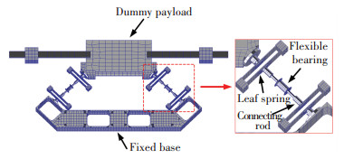
A finite element model of the VIS was developed, and was depicted in Fig. 8.The dummy payload and fixed base are modeled using Hex8 and Wedge6 elements.The connecting rod of the isolator is modeled using a Hex8 element, while a Quad4 element is used to model the flexure.The leaf spring of the elastic damping ring is modeled using a Quad4 element, and the VEM is modeled using a Hex8 element, whose material property is defined as MAT1 in MSC.Nastran®.
|
Figure 8 Finite element model of the VIS |
This model was subjected to normal mode and frequency response analyses to demonstrate the isolation effect of the isolators and arrive at a preliminary design.In general, the normal mode analysis of structures was easy to implement and the analysis results were usually consistent with the experimental results.However, it was difficult for the frequency response analysis to achieve the goal where the analysis results coincide exactly with the experimental results.The main reason for this was that the damping coefficients were hard to identify.In this study, the damping material of the isolator was the VEM.Its stiffness and damping properties vary greatly with both temperature and frequency.This makes the frequency response analysis of the VIS more difficult.
The complex VEM shear modulus G*, which affects the operational frequency ω and absolute temperature T, can be written as:
| $ {G^ * }\left( {\omega, T} \right) = G\left( {\omega, T} \right) + {\rm{i}}G'\left( {\omega, T} \right) $ | (21) |
where G(ω, T) is the shear storage modulus and G′(ω, T) is the shear loss modulus, which can be described by:
| $ G'\left( {\omega, T} \right) = \eta \left( {\omega, T} \right)G\left( {\omega, T} \right) $ | (22) |
where η(ω, T) is the loss factor, or the loss tangent.
According to classical elasticity theory, the relationship between G(ω, T) and E(ω, T) can be described as:
| $ G\left( {\omega, T} \right) = \frac{{E\left( {\omega, T} \right)}}{{2\left[{1 + \nu \left( {\omega, T} \right)} \right]}} $ | (23) |
where E(ω, T) is the real part of Young's modulus and ν(ω, T) is Poisson's ration.
Because the change in the operating temperature of the isolators in this study was very small, Eq.(21) can be rewritten as:
| $ {G^ * }\left( \omega \right) = G\left( \omega \right) + {\rm{i}}G'\left( \omega \right) = G\left( \omega \right)\left[{1 + {\rm{i}}\eta \left( \omega \right)} \right] $ | (24) |
Substituting Eq.(23) into Eq.(24), the shear modulus G* can be rewritten as:
| $ {G^ * }\left( \omega \right) = \frac{{E\left( \omega \right)}}{{2\left[{1 + \nu \left( \omega \right)} \right]}}\left[{1 + {\rm{i}}\eta \left( \omega \right)} \right] $ | (25) |
Considerable research has been undertaken to find the analysis formulae of E(ω, T), and some results from this previous work were adopted to address the modulus problems in this study.The expressions for the modulus and loss factor of the VEM can be described as:
| $ E\left( \omega \right) = \mathord{\buildrel{\lower3pt\hbox{$\scriptscriptstyle\smile$}} \over E} + \mathord{\buildrel{\lower3pt\hbox{$\scriptscriptstyle\frown$}} \over E} \left[{1-\frac{1}{{1 + {{\left( {\beta \omega } \right)}^n}}}} \right] $ | (26) |
| $ \eta \left( \omega \right) = \frac{{n{\rm{ \mathit{ π} }}\mathord{\buildrel{\lower3pt\hbox{$\scriptscriptstyle\frown$}} \over E} {{\left( {\beta \omega } \right)}^n}}}{{2E\left( \omega \right){{\left[{1 + {{\left( {\beta \omega } \right)}^n}} \right]}^2}}} $ | (27) |
where
Hence, the shear storage modulus and the shear loss modulus can respectively be described by:
| $ G\left( {\omega, T} \right) = \frac{1}{{2\left[{1 + \nu \left( \omega \right)} \right]}}\left\{ {\mathord{\buildrel{\lower3pt\hbox{$\scriptscriptstyle\smile$}} \over E} + \mathord{\buildrel{\lower3pt\hbox{$\scriptscriptstyle\frown$}} \over E} \left[{1-\frac{1}{{1 + {{\left( {\beta \omega } \right)}^n}}}} \right]} \right\} $ | (28) |
| $ G'\left( \omega \right) = G\left( \omega \right)\frac{{n{\rm{ \mathit{ π} }}\mathord{\buildrel{\lower3pt\hbox{$\scriptscriptstyle\frown$}} \over E} {{\left( {\beta \omega } \right)}^n}}}{{2E\left( \omega \right){{\left[{1 + {{\left( {\beta \omega } \right)}^n}} \right]}^2}}} $ | (29) |
The equations of motion in discrete displacement coordinates of the finite element modelu are:
| $ \left[{{{\left( {{\rm{i}}\omega } \right)}^2}\mathit{\boldsymbol{M}} + {\rm{i}}\omega \mathit{\boldsymbol{B}} + \mathit{\boldsymbol{\tilde K}}\left( \omega \right)} \right]\left\{ {\mathit{\boldsymbol{u}}\left( \omega \right)} \right\} = \left\{ {\mathit{\boldsymbol{F}}\left( \omega \right)} \right\} $ | (30) |
where
The complex stiffness matrix for the VEM elements may be written in the form:
| $ \mathit{\boldsymbol{\tilde K}}\left( f \right) = \left[{\frac{{G\left( f \right) + {\rm{i}}G'\left( f \right)}}{{{G_{{\rm{ref}}}}}}} \right]\mathit{\boldsymbol{K}} $ | (31) |
where Gref is a representative reference modulus and K is the stiffness matrix for structural elements.In Fig. 9(a) and (b) are plotted the experimentally measured values of shear modulus and loss factor of the VEM at 22 ℃.

|
Figure 9 Experimentally measured values of the VEM at 22 ℃ |
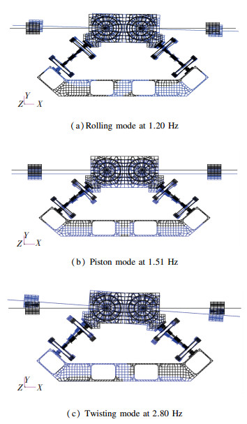
The first three natural frequencies of the system are 1.20 Hz, 1.51 Hz, and 2.8 Hz.The corresponding mode shapes are shown in Fig. 10.
|
Figure 10 The first three mode shapes of the VIS |
4 Experimental Test
This section mainly describes the experimental tests which were used to validate the validity and feasibility of the design and analysis method of this isolator.Two classes of experimental tests were carried out to investigate the properties of the vibration isolator.The first test was to measure the natural frequencies of the VIS using an impact test; the second was to measure the transmissibility of the VIS.
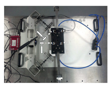
4.1 Normal Mode TestAn"impact test" was conducted to obtain the natural frequencies of the VIS.According to Fig. 10, the mode shapes of the system are the rolling, piston, and twisting modes.Accelerometers are attached to the dummy payload, whose positions are denoted by A and B as shown in Fig. 11.
|
Figure 11 Illustration of the impact test |
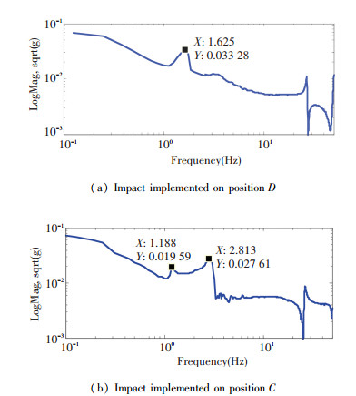
During the impact test, an"impact" was implemented at positions C and D in the directions of the arrows shown in Fig. 11.After the "impact", the dummy payload vibrated freely at the natural frequencies of the system, and the accelerometers measure the acceleration response at their corresponding positions.When an "impact" was implemented on position D, the axial natural frequency of the system was obtained.Similarly, the natural frequencies corresponding to the rolling and twisting modes were obtained.
Fig. 12 shows the frequency response for acceleration.Fig. 12(a) and (b) depicts the frequency response of acceleration when an "impact" was implemented on positions D and C, respectively.It can be seen that one peak occurred in the frequency range of 0-20 Hz in the frequency response curve of Fig. 12(a), because the motion of the system in this test was mainly along the axial direction, while the rolling and twisting modes were barely excited.There were two peaks in the frequency range of 0-20 Hz in Fig. 12(b), which was attributed to the translational motion and rotational vibration being excited in this test.
|
Figure 12 Frequency response of acceleration |
The comparison of the natural frequencies of the system obtained using the theoretical model, the FEM, and the "impact test", is shown in Table 4.It can be clearly noted that the natural frequencies obtained by the theoretical model coincided well with those obtained by the FEM and the "impact test", verifying the validity of the theoretical model and finite element simulations.
| Table 4 Natural frequencies of the VIS |
4.2 Transmissibility Test
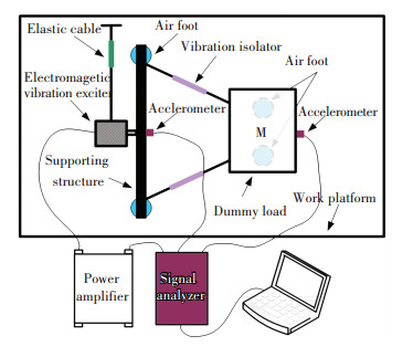
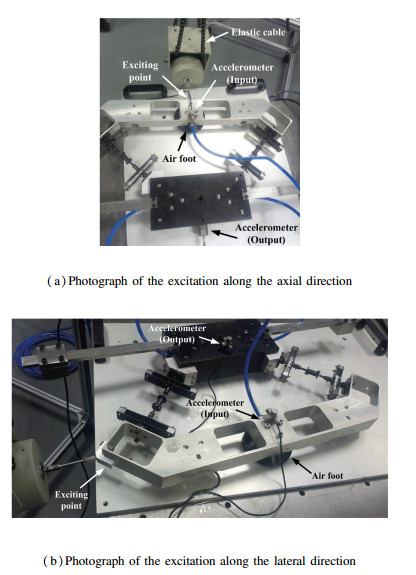
Transmissibility of the VIS was tested to evaluate the isolation effect of the isolator.Fig. 13 shows the diagrammatic drawin of the experimental setup for testing the transmissibility of the VIS.An electromagnetic vibration exciter suspended by an elastic cable was used as the excitation source.The signal analyzer provided an excitation signal to drive the electromagnetic vibration exciter via a power amplifier.Two accelerometers were placed on the support and dummy payload to measure their responses, respectively.The acceleration signals of the support and dummy payload were sent to the signal analyzer as the input signal and output signal, respectively.With the input signal and output signal, the transmissibility, relating the acceleration of the support to the acceleration of the dummy payload, can be obtained using fast Fourier transform analysis.The photographs of the excitation along different directions are as shown in Fig. 14.
|
Figure 13 Diagrammatic drawin of experimental setup |
|
Figure 14 Experimental setup for testing thetransmissibility |
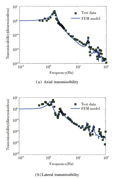
Fig. 15 depicts the transmissibility comparison of the system between the FEM model and test data.Fig. 14(a) and (b) shows the axial transmissibility and lateral transmissibility of the VIS, respectively.
|
Figure 15 Transmissibility comparison between the FEM model and test data |
From Fig. 15(a) and (b), it can be seen that the vibration attenuation effect was greater than 90% at frequencies above 5 Hz.The high-frequency resonances were well damped, so that in no case was the high-frequency vibration attenuation less than 90%.A peak occurred at the frequency of 24 Hz, which was attributed to the elastic resonance of the isolator.The local bending mode near 24 Hz was in good agreement with the frequency and amplitude.The second and higher local bending modes deviate from the prediction.Overall, the analytical results were in good correspondence with the experimental data, which indicated that the proposed analysis method used for the VEM structure was very useful in the analysis of practical engineering problems.
5 ConclusionsThis study addressed the design, theoretical modeling, analysis, and experiments of a novel compact vibration isolator for space optical payloads.A set of double-deck leaf springs was adopted in this isolator, and had the advantages of reducing the stress on the leaf springs and increasing the damping.This isolator can be adjusted to different precision payloads by changing its geometric parameters.The stiffness model of the isolator and the dynamic equation of the VIS were derived, and had been proved to be valid.An experimental setup consisting of a dummy payload floating on air-bearings was adopted to demonstrate the effectiveness of the isolator.An analysis approach is presented, which considers the characteristics of the viscoelastic material whose stiffness and damping properties vary greatly with frequency.The transmissibility test shows that the proposed analysis approach is valid, and moreover, this isolator can efficiently attenuate spacecraft born disturbances.
| [1] |
Masterson R A, Miller D W, Grogan R L. Development and validation of reaction wheel disturbance models:Empirical model. Journal of Sound and Vibration, 2002, 249(3): 575-598. DOI:10.1006/jsvi.2001.3868 ( 0) 0)
|
| [2] |
Liu C C, Jing X J, Danley S, et al. Recent advances in micro-vibration isolation. Mechanical Systems and Signal Processing, 2015, 56-57: 55-80. DOI:10.1016/j.ymssp.2014.10.007 ( 0) 0)
|
| [3] |
Davis L P, Wilson J F. Hubble space telescope reaction wheel assembly vibration isolation system.NASA Report N87-22702. Washingtong, DC: NASA, 1986, 669-690.
( 0) 0)
|
| [4] |
Pendergas K J, Schauwecker C J. Use of a passive reaction wheel jitter isolation system to meet the advanced x-ray astrophysics facility imaging performance requirements. Astronomical Telescope and Instrumentation Conference. Kona, HI, 1998. Report Number: NASA/CR-1998-207926.
( 0) 0)
|
| [5] |
Bronowicki A J. Vibration isolator for large space telescopes. Journal of Spacecraft and Rockets, 2006, 43(1): 45-53. DOI:10.2514/1.12036 ( 0) 0)
|
| [6] |
Miller S D. Investigation of a novel compact vibration isolation system for space applications. Ohio: Air Force Institute of Technology, 2010.
( 0) 0)
|
| [7] |
Kamesh D, Pandiyan R, Ghosal A. Modeling design and analysis of low frequency platform for attenuating micro-vibration in spacecraft. Journal of Sound and Vibration, 2010, 329(17): 3431-3450. DOI:10.1016/j.jsv.2010.03.008 ( 0) 0)
|
| [8] |
Kamesh D, Pandiyan R, Ghosal A. Passive vibration isolation of reaction wheel disturbances using a low frequency flexible space platform. Journal of Sound and Vibration, 2012, 331(6): 1310-1330. DOI:10.1016/j.jsv.2011.10.033 ( 0) 0)
|
| [9] |
Cobb R G, Sullivan J M, Das A, et al. Vibration isolation and suppression system for precision system for precision payloads in space. Smart Materials and Structures, 1998, 8(6): 798-812. ( 0) 0)
|
| [10] |
McMickell M B, Kreider T, Hansen E, et al. Optical payload isolation using the miniature vibration isolation system (mvis-Ⅱ).Proceedings of the SPIE, Industrial and Commercial Applications of Smart Structures Technologies. Washington: SPIE, 2007. DOI:10.1117/12.715446
( 0) 0)
|
| [11] |
Dewell L, Pedreiro N, Blaurock C, et al. Precision telescope pointing and spacecraft vibration isolation for the terrestrial planet finder coronagraph. Proceedings of the SPIE, UV/Optical/IR Space Telescopes: Innovative Technologies and Concepts Ⅱ, 2005. DOI:10.1117/12.618939
( 0) 0)
|
| [12] |
Preumont A, Horodinca M, Romanescu I, et al. A six-axis single-stage active vibration isolator based on stewart platform. Journal of Sound and Vibration, 2007, 300(3-5): 644-661. DOI:10.1016/j.jsv.2006.07.050 ( 0) 0)
|
| [13] |
de Marneffe B, Avraam M, Deraemaeker A, et al. Vibration isolation of precision payloads:A six-axis electromagnetic relaxation isolator. Journal of Guidance, Control, and Dynamics, 2009, 32(2): 395-401. DOI:10.2514/1.39414 ( 0) 0)
|
| [14] |
Pedreiro N. Spacecraft architecture for disturbance-free payload. Journal of Guidance, Control, and Dynamics, 2003, 26(5): 794-804. DOI:10.2514/2.5114 ( 0) 0)
|
| [15] |
Anderson E M, Fanson J, Davis P. Testing and application of a viscous passive damper for use in precision truss structures.Proceedings of the 32nd Structures, Structural Dynamics, and Materials Conference. Reston, VA: AIAA, 1991, 2796-2808.
( 0) 0)
|
| [16] |
Davis P, Cunningham D, Harrell J, Advanced 1. 5 Hz passive viscous isolation system.Proceedings of the 35th AIAA/ASME/ASCE/AHS/ASC Structures, Structural Dynamics, and Materials Conference. Reston, VA: AIAA, 1994, 2655-2665.
( 0) 0)
|
| [17] |
Davis P L, Cunningham D, Bicos A S, et al. Adaptable passive viscous damper:an adaptable D-StrutTM. Proceedings of the SPIE, Smart Structures and Materials 1994: Passive Damping, 1994, 47-58. DOI:10.1117/12.174114
( 0) 0)
|
| [18] |
Porter Davis L, Carter D R, Hyde T T. Second generation hybrid D-strut.Proceedings of the SPIE, Smart Structures and Materials 1995:Passive Damping. Washington: SPIE, 1995, 161-175. DOI:10.1117/12.208885
( 0) 0)
|
| [19] |
Ruebsamen D T, Boyd J, Vecera J, et al. Development of a dual mode D-strut vibration isolator for a laser communication terminal. Proceedings of the 38th Aerospace Mechanisms Symposium, Langley Research Center, Washington: SPIE, 2006, 141-148.
( 0) 0)
|
| [20] |
Hindel T, Davis T, Fischer J. Isolation, pointing, and suppression (IPS) system for high performance spacecraft.Proceedings of the SPIE, Industrial and Commercial Applications of Smart Structures Technologies. Washington: SPIE, 2007. DOI:10.1117/12.720663
( 0) 0)
|
| [21] |
Brennan S, Bronowicki A, Ryan P, et al. Control structure interaction testbed:passive isolation, simulation and test.Proceedings of the 47th AIAA/ASME/ASCE/AHS/ASC Structures, Structural Dynamics, and Materials Conference 14th AIAA/ASME/AHS Adaptive Structures Conference 7th. Reston, VA: AIAA, 2006, 1-17. DOI:10.2514/6.2006-1834
( 0) 0)
|
| [22] |
Camelo V, Bronowicki A, Simonian S, et al. Damping and isolation concepts for vibration suppression and pointing performance.Proceedings of the 50th AIAA/ASME/ASCE/AHS/ASC Structures, Structural Dynamics, and Materials Conference. Reston, VA: AIAA, 2009, 2009-2637.
( 0) 0)
|
| [23] |
Sullivan J M, Gooding J C, Idle M K, et al. Performance testing for an active/passive vibration isolation and steering system. AIAA Dynamics Specialists Conference.Reston VA: AIAA, 1996, 87-97.
( 0) 0)
|
 2018, Vol. 25


