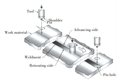
Friction stir based technologies have been attracting global attention because of their favourable features with respect to the process and the resultant products[1]. In particular, friction stir welding (FSW) process is often used for the welding and processing of softer structural materials such as Al, Mg and few Cu alloys[2-4]. An FSW setup constitutes two parts, the welding machine and the FSW tool. The available welding machines are either position control or pressure control type. The FSW tool comprises a shoulder and a pin. The principle of FSW can be narrowed down as a tool-workpiece interaction which results in several complex thermomechanical phenomena[5]. The FSW process involves four stages namely plunge stage, dwell stage, welding stage and tool retraction stage. A schematic of the FSW process is shown in Fig. 1. In the plunge stage, the pin of a rotating tool is slowly driven through the workpieces[6] until the shoulder comes into contact with the top surface of the workpiece. In the dwell stage, the plunged tool is continued to rotate for a while. Heat is generated due to friction between the tool and the workpiece, and due to plastic deformation of the workpiece[7], causing a softening of the workpiece around the tool[8]. The next is the welding stage where the rotating tool is traversed through the workpieces along the intended weld line. The tool rotation and translation drive the softened material in front of the tool (leading side) to behind the tool (trailing side) and cause intermixing of materials[7]. This produces a welded joint. After covering the desired weld distance, the tool is immediately pulled out of the workpiece.
|
Figure 1 Schematic of FSW process[6] |
The integrity of the FSW joints depends upon several factors. The material and design of the FSW tool, the material and thickness of the backing plate and the welding parameters (i.e., the rotation speed, welding speed, shoulder plunge depth, tool tilt angle) affect the heat generation and material flow in the welding process and ultimately, influence the microstructure and mechanical properties of welded joint of a given material[2, 7, 9-16]. Therefore, appropriate selection of FSW tool and optimization of welding parameters are of utmost importance to achieve a sound FSW joint. An improper choice of welding parameters can result in excessive heat input, temperature gradient, strain and strain rate can cause defects formation[16-19]. A pool of investigations on the effect of welding parameters on the FSW process and its welded joints further reveals the importance of optimization of welding parameters[20-23].
The FSW process has been successfully employed to perform the welding of square butt, T-butt, lap and edge butt configurations [2, 24-25] of softer Al and Mg alloys and few Cu alloys and their dissimilar combinations in various manufacturing applications[2, 5, 8, 26-28]. Recently, the technology has been introduced to the welding of conical interfaces such as pipes. Being a solid state process, FSW enjoys multiple advantages over the fusion welding processes. For example, FSW does not use filler material which reduces the weight of welded components and helps in cutting down the energy consumption when the component is employed in service[2, 29-30]. No fume or harmful emission is produced[2, 12] which makes FSW a green technology. Additionally, the detrimental fusion weld defects such as solidification cracking, porosity and shrinkage, commonly occurred in fusion welding processes, are prevented in FSW because the material joining takes place in an almost solid state and low heat input[5, 13]. Apart from the above advantages, a reasonable compromise between sustainability (i.e., energy-efficiency, eco-friendliness and cost-effectiveness) of the process and soundness of the welded joint entices a variety of manufacturing sectors[2, 5, 29-32] which include automotive, maritime, aerospace[30-31], railways[30], electronic packaging etc. to adopt FSW over the fusion welding processes. In the above applications, an FSW tool made of steel seems to serve adequately.
Despite such astounding success and large attention, the FSW process is still associated with limitations. For instance, inadequate heat generation and workpiece softening in FSW reduce the material flow which produces defective welded joints[33-38]. Besides, the massive downward axial force, welding force applied to accomplish the welding and the corresponding tool torque pose the risk of rapid tool wear, reduced tool life and performance and even tool failure[15, 38-39]. Also, the size of the FSW equipment requires being large enough to supply and withstand such massive loads[40]. FSW has not been as robust for harder materials[41-45] (e.g. mild steels, stainless steels, titanium alloys[2, 5, 26, 28, 46-47], nickel alloys[15], lead alloys, and few metal matrix composites[48]) as for the Al alloys although some dissimilar combinations comprising of one softer material and one harder material are tested. In such dissimilar FSW, the harder material is frequently positioned at the advancing side (AS) and the tool offset is set on the softer material[49-51]. Laboratory scale tests showed that FSW is feasible to harder and high melting point materials. However, industrial implementation of FSW to the harder materials appears a distant possibility. The reason is that the steel tools, commonly used in the welding of softer alloys, are unsuitable for the welding of harder materials[15, 45, 47, 52-53]. This is primarily due to the risk of tool wear and failure and secondarily due to inadequate amounts of heat generation and plastic deformation. The issue of tool can still be resolved by replacing the steel tool with tools made of extremely durable materials[15, 54-56] such as polycrystalline cubic boron nitride pcBN[57-58], WC-based alloy[59-61], Ni alloy[62], Co alloy[63], Si3N4[64-67], and lr alloy[68-70]. However, such a replacement would cause a multifold increase in the cost of production. These issues distract the implementation of FSW to harder materials. Another issue of FSW is the low productivity because the permissible welding speeds in FSW are low and fall within a narrow window.
However, commitment to improving the technological feasibility and sustainability of FSW has driven the research fraternity to conduct numerous investigations and amendments on various aspects of the process over time. These studies have resulted in a rapid progress in process design, experimental investigation and numerical modelling and a smooth emergence of FSW. From a concrete viewpoint, the aim of modern researches on FSW can be broken down into the following components[2, 5, 24, 29-32, 41-44, 71-76]: a) improving the sustainability of the very FSW technology; b) understanding the science behind the various physical phenomena of the FSW process and c) expanding the existing FSW technology to harder alloys and dissimilar material combinations of ferrous and non-ferrous metals, composites and plastics[76]. To architect the FSW process into a next generation prospect of welding, a complete understanding and development of a universally robust FSW technology are of paramount importance. Within years of inception of FSW, it has been understood that sufficient plasticization of the workpiece is the basic criteria to be looked into in order to expand the application of FSW to a wide variety of harder materials. While the development of durable tools appears to be an immediate option for the expansion, the associated high production cost restricts its commercial application. An alternate option is assistant softening of the workpieces participating in the FSW process by applying an external secondary energy. From a theoretical standpoint, the assistant softening would add to the actual plasticization of the workpieces achieved by tool-workpiece interaction. This would enhance the overall plasticization of the workpiece during the FSW. Based on this principle, energy from several thermal and ultrasonic sources has been added to the FSW process. As a result, a number of secondary energy assisted FSW variants are developed, most of which are presented in a recent review by Padhy et al.[77] However, they had pointed out that the investigations on microstructure aspects and process modelling were too few. In the view of the growing interest, the research in this direction is making a rapid progress. This paper presents a quick look at secondary energy assisted FSW processes. Also, it provides a detailed account of the state-of-the-art of ultrasonic vibration assisted FSW process (UVAFSW) and the influence of ultrasonic vibrations on various aspects of the process and the microstructure and mechanical properties of the welded joints.
2 Secondary Energy Assisted FSW ProcessesAccording to the current understanding, the main aim of integrating a secondary energy with the FSW process is to achieve an enhanced overall softening of the workpiece. Such integration may be associated with certain advantages and limitations with respect to the process and the quality of the welded joint. Within just over a decade, much secondary energy assisted FSW processes have emerged [77]. The secondary energy applied in FSW is either in the form of thermal energy or ultrasonic vibrations. A variety of sources such as electricity, laser, plasma, induction coil, TIG arc etc. have been employed to supply the thermal energy to the FSW process while ultrasonic vibrations are the only form of mechanical energy used for the assistant softening in FSW. Kohn et al.[39] employed a laser to assist the FSW of AZ91D Mg alloy. In their study, the workpieces were preheated using a laser source leading the FSW tool. The precursor laser preheating reduced the large loads in the process. Merklein et al.[78] preheated the steel workpiece using a diode laser spot in the dissimilar FSW of steel to Al alloy. The laser preheating increased the welding speed, improved the weldability while it reduced the tool wear. Casalino et al.[79] combined a Yb fibre laser source with FSW to preheat wrought AA 5754H111 workpieces.
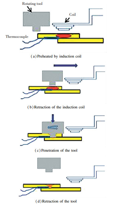
Induction heating is another assistant thermal energy used to improve the FSW process.In the spot FSW of 1.6 mm thick plates of S12C low carbon steel, Sun et al.[80] integrated high-frequency induction heating with FSW to preheat the workpiece material in front of the tool. Schematic of the above induction heating assisted FSW in Fig. 2 and Fig. 3 shows various stages of the process. The assistant induction preheating produced welded joints of better quality as compared to those without the preheating. Álvarez et al.[81] evaluated the role of assistant induction preheating in FSW by analyzing microstructure and mechanical properties of the welded joints of 5 mm thick cast super duplex stainless steel (GX2CrNiMoN26-7-4) plates. The presence of induction preheating caused a reduction in the welding force, a substantial decrease in grain size in the weld nugget zone and an increase in the tensile strength and hardness of the welded joint.
|
Figure 2 Schematic of the various stages of preheat-assisted spot FSW process[80] |

|
Figure 3 Process assembly during the spot FSW process[80] |
Some researchers employed resistance heating by electric current as the secondary energyin FSW. Luo et al.[82] employed the resistance heating assisted FSW process to weld 5 mm thick plates of AZ31B Mg and 7075 alloys. They investigated the influence of electric current intensity on the weld seam by flowing the electric current through the FSW tool via the contact interface into the workpieces. The weld nugget zone (WNZ) of AZ31B joint attained higher refinement and hardness with increasing current density. This was attributed to the resistance preheating based augmented plastic deformation. However, the increase in current density has resulted in a slight grain coarsening both in the WNZ and in the HAZ. The electric current assisted FSW successfully joined the high-strength steel alloys such as 2Cr13Mn9Ni4 and Q235B[82]. In order to localize the resistance preheating to the weld zone, Liu et al.[83] developed an electrically assisted FSW set up where the electric current was supplied by two copper brushes, working as anode and cathode, pressed against the workpiece surface. This set up was used in the welding of dissimilar alloys Al 6061 to TRIP 780. The observed smooth plunge stage and reduction in downward axial force was attributed to the combined influence of electro-plastic effect and Joule heating. Besides, the assistant electric current has strengthened the weld joint by creating micro-interlock features at the Al-Fe weld interface.
Apart from the above, tungsten inert gas (TIG) arc and plasma arc are the two arc based secondary energy sources employed to assist the FSW process. Bang et al.[84] preheated the harder alloy using a TIG arc in the dissimilar FSW of AA 6061-T6 alloy to Ti-6Al-4V alloy plates of thickness 3.5 mm. A significant increase in the tensile strength and elongation of the arc assisted FSW joints was observed. Besides, the fracture pattern of the welded joint changed from brittle to the dominant ductile mode in the presence of the TIG arc preheating. In a separate study, Bang et al.[85] had observed similar improvement in the weld mechanical properties when they employed TIG arc to assist the dissimilar FSW of STS304 stainless steel to AA6061. The improved weld mechanical properties were attributed to an enhanced material flow due to the arc preheating induced assistant softening. Yaduwanshi et al.[86] employed plasma arc as a secondary heat source in the FSW of AA1100. The observed reduction in the downward force was ascribed to an enhanced material plasticization in the presence of the plasma arc based preheating of the workpiece. In the presence of the plasma arc, WNZ of the welded joint was found to be more refined than that without the arc. Yaduwanshi et al.[87] had also conducted numerical modelling of the plasma arc assisted FSW process to understand the effect of the plasma preheating on the process and on the welded joint.
To sum up, the straightforward role of the assistant thermal energy in FSW is preheating of the workpiece. The preheating usually results in a substantial reduction in the applied downward force, improvement in the material flow, increase in tensile strength, elongation and hardness of the welded joint, and makes the FSW process feasible to harder ferrous and non-ferrous alloys. The positive effects can be attributed to an additional plasticization of the workpiece due to the preheating. Ultimately, application of the assistant thermal energy in FSW reduces the tool wear, increased the tool life and hence, may reduce the production cost. However, the thermally assisted FSW processes are still in their infancy. They must be studied in great details to understand the fundamentals of various physical phenomena involved in the processes and the microstructure evolution and mechanical properties of the welded joints. Also, progress must be made towards the development of numerical process models and upgradation of technology to make these processes compatible and robust to industry culture. A comprehensive review of the progress of thermal energy assisted FSW processes can be found elsewhere[77].
Although beneficial, the thermal energy as an assistant in FSW attaches certain disadvantages, both to the process and the welded joint, which were listed down by Padhy et al.[77] Some striking examples are, the laser is associated with the issue of energy loss by reflection, induction heating can be used only to electrically conducting workpieces, preheating by TIG or plasma arc is associated with global heating and consequent microstructural damage of the entire workpiece, constriction of resistance heating to the weld zone requires heavy modifications in the equipment etc.[39, 77-91] The above issues and many other disadvantages associated with the application of thermal energy as an assistant in FSW encourage researchers to embrace ultrasonic vibrations, known for causing acoustic softening in metals, as the secondary energy in FSW to achieve the necessary assistant softening and process effectiveness.
3 Acoustic Softening EffectIt is long known that ultrasonic vibrations of frequency 20 kHz and/or above, when superimposed on applied the static loads of a process, can reduce the yield stress of metals via a well-studied low-stress deformation phenomenon known as acoustic softening[92-96]. The acoustic softening also adds some favourable properties to the metal, sometimes without causing significant heating or microstructure modification[93, 95-96]. Investigations on the effect of ultrasonic vibrations on the metal plasticity revealed that ultrasonic vibrations induce a low-level internal heating in the realms close to the dislocations in the metal. This weakens the dislocation vicinity and causes the release of arrested dislocations. It appears that the increase in dislocation density decreases the mean free path of dislocation which allows them to remain as free dislocations. Subsequent application of an external load raises the dislocation mobility which decreases the yield stress of the metal[93] and increases its overall degree of deformation. The acoustic softening is analogous to thermal softening. Nevertheless, it is shown that the ultrasonic energy producing a given degree of softening is 107 times less than the thermal energy needed to produce an equivalent degree of softening[92-93]. This is because the thermal energy or heat is absorbed almost uniformly across the metal plate based on upon its anisotropy whereas the ultrasonic vibrations are absorbed preferably at the metal inconsistencies such as the dislocations and grain boundaries while their effect on the defect-free zones of the metal remains negligible[93, 97-99]. Following the beneficial effects, ultrasonic vibrations have been employed in several welding and metal processing engineering and technologies such as metal forming, hot-press joining, ultrasonic machining or cutting, ultrasonic consolidation etc.[100-103], which has been aptly compiled in a recent review by Kumar et al.[104] In these manufacturing processes, the coupling of ultrasonic vibrations caused a reduction in the applied loads and process time[102, 105] and minimized the percentage of process failure[106]. Also, the presence of ultrasonic vibrations improved the quality and performance of the welded or processed product by preventing the formation of crack and wrinkle[107]. In the view of the above advantages, ultrasonic vibration has been employed as a potential secondary energy to assist the FSW process. The following section presents a comprehensive review on the state-of-the-art of ultrasonic vibration assisted FSW processes and the implications of ultrasonic vibrations on the FSW process variables (welding loads, heat generation, weld temperature, material flow, material viscosity, flow velocity etc.) and on the microstructure and mechanical properties of the welded joint.
4 Ultrasonic Vibration Assisted FSW(UVAFSW) ProcessThe UVAFSW process has established ground in recent years. The objective of supplying ultrasonic vibrations into the FSW process is to achieve higher process effectiveness and weld performance. Various types of ultrasonic assisted FSW setups are reported in the literature. These setups comprise of two major parts: ultrasonic system and FSW machine. These two parts are coupled together in the ultrasonic vibration assisted FSW (UVAFSW) process.
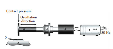
4.1 Ultrasonic SystemIn UVAFSW, the purpose of the ultrasonic system is to assist the FSW process by transmitting sufficient vibrational energy into the workpiece during the welding stage. Schematic of an ultrasonic system used by Strass et al.[108] is shown in Fig. 4. In general, the ultrasonic systems employed in the various types of UVAFSW processes consist of four basic components: ultrasonic generator, piezoelectric converter/transducer, booster and sonotrode, connected in a series. Each of the above components is briefly discussed below[77, 109-111].
|
1-Ultrasonic generator; 2-Piezoelectrical converter; 3-Booster; 4-Sonotrode; 5-Joining partner; 6-Anvil Figure 4 Schematic of ultrasonic power system[108] |
1) The ultrasonic generator is connected to a power source. It transforms electrical power into high-frequency sinusoidal waves of frequency 20 kHz or above. These waves are processed further by the other components in the series.
2) The transducer(also known as a piezoelectric converter) converts the high-frequency waves into mechanical vibrations of identical frequency. However the amplitude of these vibrations remains too small to use in practice.
3) The booster amplifies the low amplitudes vibrations into vibrations of amplitude as high as 50 μ m. This is an important step because some material properties are highly controlled by the vibration amplitude.
4) The sonotrode (also known as an ultrasonic horn) exerts the amplified ultrasonic vibrations into the desired area.
The UVAFSW process, the ultrasonic system is arranged with respect to the FSW machine to facilitate the application of ultrasonic vibrations on the intended target. Several modes of ultrasonic supply have been reported although none has been standardized so far.
4.2 Modes of Ultrasonic Exertion in FSW ProcessThe reported studies on UVAFSW processes show that ultrasonic vibrations have been supplied into the FSW process via various modes or routes. Overall, five modes of ultrasonic exertion in FSW can be found in the literature. These modes of ultrasonic supply, their advantages and disadvantages are discussed below.
4.2.1 Mode 1: Ultrasonic vibrations exerted horizontally on FSW toolPark et al.[112] were the first to report the UVAFSW process. Schematic of their UVAFSW setup is shown in Fig. 5. In this setup, the sonotrode of the ultrasonic system consists of bearings which remain in contact with the FSW tool. In order to maintain the contact, arrangements are made to traverse the sonotrode at the same speed as the FSW tool. Using this ultrasonic system, the ultrasonic vibrations are exerted horizontally on the FSW tool which subsequently is transmitted into the weld zone of the workpieces during the welding process. Hereinafter, this mode of ultrasonic exertion in FSW will be referred to as Mode 1. Park et al.[112] pointed out that the sonotrode/horn design is of significant importance in the view of process effectiveness and weld performance. Hence, the horn should be designed and manufactured with great caution.

|
Figure 5 Schematic of the UVAFSW set up using the mode 1 exertion (horizontally on tool)[112] |
The Mode 1 ultrasonic exertion attached positive effects on the FSW process and weld quality. However, Lai et al.[113] pointed that the above mode of ultrasonic transfer has certain inherent disadvantages. The transfer of ultrasonic vibrations via the bearings and the FSW tool to the workpiece requires multiple links. These links are the points of huge energy loss. Therefore, the horizontal transfer of ultrasonic vibrations would involve poor transfer efficiency. Further, maintenance of the tool-sonotrode contact involves a horizontal load. This load may cause breakdown and damage of the tool or the sonotrode.
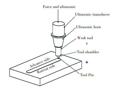
4.2.2 Mode 2: Ultrasonic vibrations exerted vertically on FSW toolIn order to prevent the energy loss due to the multiple links, Lai et al.[113] developed an alternate ultrasonic system where the vibrations are exerted vertically on the FSW tool. Schematic of their ultrasonic system is shown in Fig. 6. In this system, a partial segment of the ultrasonic system (i.e., the transducer, booster and horn in series) is mounted on the top of the tool. The tool along with the partial segment is placed in the slot for the tool in the FSW machine. The partial segment receives input power from a remote ultrasonic generator. The input power is converted into high-frequency mechanical vibrations and exerted on the tool. With this arrangement, it is possible to apply ultrasonic vibrations to the tool from the point of application of downward force. Also, the ultrasonic vibrations are exerted perpendicularly into the workpieces during welding. Hereinafter, this mode of ultrasonic exertion in FSW will be referred to as Mode 2. This system provides means of transferring the assistant ultrasonic energy through the tool vertically onto the workpiece. This involves no bearings and hence eliminates the risk of energy loss due to the linkage points[112]. However, accommodation of this ultrasonic system requires heavy modification of the FSW machine.
|
Figure 6 Schematic of the UVAFSW set up using the mode 2 exertion (vertically on tool)[113] |
4.2.3 Mode 3: Ultrasonic vibrations exerted angularly on workpiece
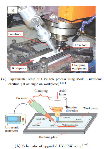
Wu et al.[114-117] had developed the so called ultrasonic vibration enhanced friction stir welding (UVeFSW), an FSW variant where ultrasonic vibrations assisted the FSW process. A photograph of the UVeFSW setup is shown in Fig. 7(a). In this setup, however, the approach adopted for application of ultrasonic energy in the FSW process is entirely different from those used by Park et al.[112] and Lai et al.[113] From Fig. 7(a), it is clear that the ultrasonic system in UVeFSW is isolated from the FSW tool. This system is built by connecting the four components (i.e., the generator, transducer, booster and horn) in series and is fixed to the main spindle of the FSW machine using a simple fixture. During the welding, the sonotrode is lowered to contact with the workpiece near and ahead of the FSW tool. When in contact, the sonotrode makes an angle of 40° with the surface of the workpiece. The distance between the axis of the tool and the point of sonotrode contact is 20 mm. In this state, the tool traverse to accomplish the welding makes the sonotrode move automatically in front of the tool and exert ultrasonic vibrations along the desired weld seam. Generally, a small force (300 N) is applied on the sonotrode to maintain its contact with the workpiece during the welding. Hereinafter, this mode of ultrasonic exertion in FSW will be referred to as Mode 3. The UVeFSW setup has been used in the welding of aluminium alloys[118-119] and in the dissimilar FSW of Al alloy to Mg alloy[120].
|
Figure 7 Experimental setup of UVeFSW process using Mode 3 ultrasonic exertion and schematic of upgraded UVeFSW setup |
The main advantage of this ultrasonic system is that it is simple and isolated. Thus, it requires no permanent modification in the FSW machine. It transfers ultrasonic vibrations directly onto the workpiece. Therefore, the uncertainties and limitations associated with the energy loss due to integrations or links are eliminated. Also, since the application of ultrasonic vibrations does not involve the FSW tool, this method presents no risk towards the tool life and performance. Although useful, Tarasov et al.[122] pointed out that the above angular mode of ultrasonic exertion was similar to ultrasonic impact treatment (UIT). They predicted that the Mode 3 arrangement may lack a firm sonotrode-workpiece contact which may lead to energy loss and inefficient energy transfer. However, Liu et al.[123] had calculated that the energy transfer efficiency using this angular mode is 83%, which indicated that the energy transfer is reasonably efficient. Further, this is the most developed and progressed method among all the modes. The studies include the experimental investigations on the process variables, thermal cycles, welding loads, material flow, morphology, microstructure and mechanical properties of welded joints and numerical simulations of the UVeFSW process. Further, the effects of ultrasonic vibrations on the above aspects have also been aptly studied by comparing the results from welded joints with and without ultrasonic vibrations. Recently, Zhong et al.[114] had developed an upgraded UVeFSW setup where a pneumatic control adjusted the contact force between the sonotrode and the workpiece. A schematic of the upgraded system is shown in Fig. 7(b). The pneumatic control ensures a stable contact force and thus, makes the results of this process more reliable.
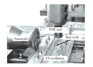
4.2.4 Mode 4: Ultrasonic vibrations exerted laterally on workpieceThis mode of ultrasonic exertion in FSW was conducted by Strass et al.[111] Their objective was to achieve broken and shattered intermetallic compounds in the dissimilar joining of Al alloy to Mg alloy. A photograph of their ultrasound supported FSW (US-FSW) setup has been shown in Fig. 8. In this setup, the ultrasonic system is exactly same as that shown in Fig. 4. The sonotrode of the ultrasonic system is arranged in such a manner that it transmits ultrasonic vibrations on one side of the workpieces during welding. Hereinafter, this mode of ultrasonic exertion in FSW will be referred to as Mode 4. Using the US-FSW, a reduction in intermetallic compounds and increase in mechanical properties of the welded joints have been reported[108, 110, 124]. Nevertheless, Padhy et al.[77] pointed out that the region of ultrasonic exertion in Mode 4 is far from the virtual weld zone. This would cause an insufficient transfer of ultrasonic energy to the weld zone.
|
Figure 8 Experimental setup of US-FSW using mode 4 ultrasonic exertions (laterally on the workpiece)[111] |
4.2.5 Mode 5: Ultrasonic vibrations exerted on backing plate
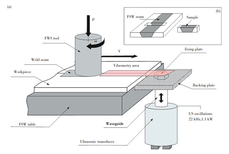
Tarasov et al.[122, 125] devised a UVAFSW system where the mode of ultrasonic exertion was completely different from those discussed above. A schematic of their UVAFSW system is shown in Fig. 9. In this system, an immovable stiff sonotrode is bolted at the bottom of the backing plate. During welding, ultrasonic vibrations are exerted by the sonotrode on the backing plate. Subsequently, the vibrations are transmitted to the workpieces across the coloured area in Fig. 9. This is a relatively new system which is yet to be investigated extensively. Hereinafter, this mode of ultrasonic exertion in FSW will be referred to as Mode 5. Using this arrangement, the contact between the sonotrode and backing plate appears to be intact and the ultrasonic transfer efficiency seems good during the welding process. However, the energy transfer to the localized area of the weld zone may differ from location to location in the weld zone because the sonotrode is fixed and exerts energy at a fixed location of the backing plate. Therefore, the overall thermomechanical effect on the weld zone may not be uniform throughout the workpiece because the propagation of ultrasonic vibrations in the metals may be annihilated with increasing distance. This would cause the ultrasonic energy to vary from one point to another along the weld line. The points near the sonotrode would receive higher energy while those far from the sonotrode would receive lower energy.
|
Figure 9 (a) Schematic of ultrasonic exertion via the backing plate (Mode 5 ultrasonic exertion) and (b) workpiece view[122] |
With the above knowledge about the types of ultrasonic exertion modes, the next section of this review will focus on the reported results on the process variables and quality of welded joint in FSW with ultrasonic vibrations.
5 Influences of Ultrasonic in FSW on Process Variables and Joint Quality 5.1 Welding LoadsIn FSW, the tool is an important component which determines the feasibility of the process, quality of welded joint and cost of production. However, it is subjected to different forces or loads i.e., downward axial force, welding force and spindle torque during the welding process. These loads often cause tool wear and reduce the tool life and performance. Therefore, it is essential to design and manufacture compatible tools to achieve extended life and better performance of the tool and sound welded joints at lower production cost. The design and engineering of FSW tool are of paramount importance and a great deal of research is in progress to improve the tool technology.
Basically, the lower are the applied loads on the tool, the lesser would be the tool wear rate. The loads on the tool would be lower if the workpiece offers a lower resistance to plastic deformation during the FSW process. It is known that ultrasonic vibrations in FSW cause assistant softening of the workpieces. Therefore, the workpiece with ultrasonic vibrations would offer a lower resistance to plastic deformation and material transport than that without the vibrations. Based on the above, examination of the welding loads in the presence of ultrasonic vibrations in FSW is essential. Measurement of the welding loads is conducted using a load cell available in the FSW machine. The loads are measured during all the four stages of FSW, namely the plunge, dwell, weld and retract stages.
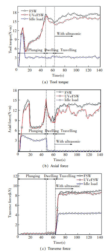
Fig. 10, reported by Zhong et al.[114], shows the comparisons of various welding loads in FSW without ultrasonic vibrations and with Mode 3 vibrations in FSW (i.e., UVeFSW). The variations in each of these loads during the FSW and UVeFSW processes are not the same although they follow similar trends. The trends of variations are based on a number of these forces necessary at various stages of each process and are described elsewhere[114]. Fig. 10(a) shows the variations in tool torque during the various stages of FSW and UVeFSW. The tool torques during the plunge and dwell stages of FSW are similar to their counterparts in UVeFSW. This is because, in Mode 3, the ultrasonic vibrations are exerted only during the welding stage. In Fig. 10(a), the reduction in tool torque during the welding stage is apparent in the presence of ultrasonic vibrations in FSW. Similar reductions in the downward axial force and traverse force/welding force in the welding stage of UVeFSW can be observed from Fig. 9(b) and (c). The reduction in welding loads may be attributed to an improved tendency of the material in the weld zone for plastic deformation due to the assistant ultrasonic softening.
|
Figure 10 Welding loads in FSW and UAFSW systems at (ω = 800 r/min and ν =110 mm/min) [114] |
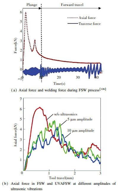
Fig. 11(a) shows the variation in axial force and welding force as a function of welding time using the Mode 1 ultrasonic exertion in FSW. It is evident that the welding force is considerably lower than the axial force. Both these forces depend upon the welding parameters.
|
Figure 11 Axial force and welding force during FSW process[126] and axial force in FSW and UVAFSW at different amplitudes of ultrasonic vibrations (ω =1 500 r/min and ν = 25 mm/min)[127] |
In Fig. 11(a), the first peak of axial force in the plunge stage represents the load exerted when the tool just contacts the workpiece while the second peak shows the load when the shoulder contacts the workpiece surface[126]. From Fig. 11(b), it is evident that the axial force decreases with increasing amplitude of ultrasonic vibration[127]. Also, the axial force is reduced by 25% with the application of ultrasonic vibrations[126-127]. This reduction can be attributed to an increased heat generation and higher plasticization of material by the additional ultrasonic energy on the tool[112]. Finite element simulation of the UVAFSW process by Park et al.[126] had further predicted a significant decrease in the axial force due to the ultrasonic vibrations in FSW process.
Amini et al.[128] found that the influence of ultrasonic vibrations on the axial force and welding force vary with a welding speed of the process. The axial force decreased with increasing rotational speed in UVAFSW. The maximum reduction in the axial force with ultrasonic vibrations in FSW was 25%. Such reduction in the process forces was also observed in friction stir processing (FSP) applications. Kumar attributed these reductions to the ultrasonic induced softening of the workpieces[129] Montazerolghaem et al.[130] conducted an experimental investigation and numerical simulation of FSW and vibration assisted FSW processes to study the influence of ultrasonic vibrations on welding loads. A 17% decrease in axial force was achieved in the presence of vibrations in FSW. In summary, application of ultrasonic vibrations in FSW caused a reduction in the axial force, welding force and tool torque irrespective of the mode of ultrasonic exertion.
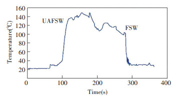
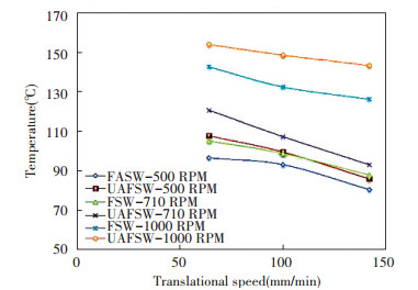
5.2 Thermal HistoryHeat generation and thermal history are two important aspects of any welding process.In FSW, heat is generated initially due to the friction between tool and workpiece and later due to the plastic deformation of the workpiece[26]. The heat generation and thermal history of FSW process depend upon the process parameters. When ultrasonic vibrations are applied in the FSW process, the heat generation is complemented by two more factors, the sonotrode-workpiece interaction and heating due to ultrasonic vibrations. Amini et al.[128] observed that the reduction in axial force due to increasing rotation speed was due to increase in process temperature and subsequent material deformation. Their study revealed that for a given set of welding speed and rotational speed, the process temperature in UVAFSW was higher than that in FSW, as shown in Fig. 12. The increase in temperature was attributed to the higher stirring of material. When ultrasonic vibrations were present in FSW, increase in rotational speed at a constant welding speed caused a higher rise in tool temperature while the increase in welding speed at a constant rotational speed caused a lower drop in tool temperature, as shown in Fig. 13. The decrease in tool temperature with increasing welding speed was attributed to a lesser number of tool rotations and thus, material stirring.
|
Figure 12 Variation in tool temperature in UVAFSW and FSW at 1 000 r/min and 100 mm/min[128] |
|
Figure 13 Influence of feed speed on tool temperature[128] |
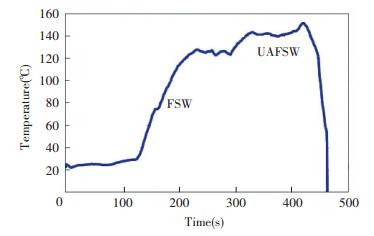
In a separate work, Amini et al.[131] used a bending vibration tool for efficient transfer of ultrasonic vibrations into the FSW process. The tool shoulder temperature profile of the FSW process using the bending vibration tool is shown in Fig. 14. An increase in tool shoulder temperature and consequently, a reduction in the axial force and welding force was observed when ultrasonic vibrations were applied into the FSW process using the bending vibration tool. Correlating the variations in shoulder temperature to that of the weld zone, the reduction in process load was attributed to the increase in process temperature[126].
|
Figure 14 Temperature of tool shoulder with and without bending vibrations[131] |
From the above, it is evident that ultrasonic vibrations cause an increase in the FSW process temperature. Lai et al.[113] elaborated the above assertion using experiments and numerical simulations. In their study, ultrasonic vibrations were exerted in Mode 2, i.e., vertically on the FSW tool. They observed that, the influence of ultrasonic vibrations on temperature field is relatively less obvious at lower welding speeds than at higher welding speeds. At lower welding speeds, the temperature fields of FSW and UVAFSW were identical while the increase in welding speed induced a higher temperature decrease in the FSW process than in the UVAFSW process. Thus, the maximum temperature was always higher in UVAFSW. This was attributed to the additional heat input due to the ultrasonic vibrations. The numerical simulations also predicted that the process parameter window of UVAFSW process is wider than that of FSW process. Using Mode 3 ultrasonic exertion, it was observed that the heating of workpiece in UVeFSW is relatively faster than that in FSW although the peak temperatures of both the processes are similar. Also, the temperature generated by the isolated angular ultrasonic exertion on the workpiece depends upon the welding speed of process[114]. Using Mode 3, the actual temperature generated by the isolated sonotrode was not reflected completely in the UVeFSW process, as shown in Fig. 15, because of the 2-3 s time delay between the sonotrode and the workpiece. This lower temperature rise may be beneficial towards the microstructure of the welded joint. On the other hand, the temperature field in FSW was asymmetric[132].

|
Figure 15 Thermal cycles of FSW, UVeFSW and isolated ultrasonic exertion processes at ω =400 r/min, ν =65 mm/min[114] |
5.3 Material Flow
The weld formation in FSW involves several complex stages such as heat generation, material flow and material mixing, microstructure evolution etc. The material and dimensions of the workpiece, the material and design of the FSW tool and the welding parameters play key roles in producing the welded joint. Ultrasonic vibrations in the FSW process alter the process variables and influence the joint formation. Material flow is one such variable which can be affected by the exerted vibrations. Therefore it is important to understand the effect of ultrasonic vibrations on material flow to understand and control the process and the properties of the welded joint. In general, material flow in FSW joints is investigated by adopting marker insert technique, stop action technique and welding of dissimilar materials. It is known that the material flow in FSW is complex while the addition of ultrasonic vibrations to the FSW process causes assistant softening of the workpiece. This softening makes the deformation and flow of workpiece easier during the welding process[133]. Recently, Liu et al.[123, 134-135] using Mode 3 ultrasonic exertion, compared material flow in the FSW and UVeFSW of aluminium alloys using pure aluminium foil as marker insert and sudden stop action technique. Fig. 16(a) and (b) show the macrographs of exit-holes in FSW and UVeFSW, respectively. These figures reveal that the trajectory of the marker insert is increased in UVeFSW. This was due to an increased degree of plasticization, and stirring of material in the presence of ultrasonic vibrations, indicating improved material flow and mixing. The strain/strain rate of the weld in UVeFSW was found to be higher than that in FSW[123]. These observations are supported by the numerical simulations of FSW and UVeFSW process, conducted by Shi et al.[121, 136-137]. The numerical simulations predicted a higher heat generation, decrease in material viscosity and increase in material flow velocity around the pin. These cause an expansion of the window of safe process parameters for FSW process. The higher volume of deformed material near the pin, increase flow velocity, sufficient material flow in the pin affected zone and enlarged flow region causes a reduction in the time delay between material flows of various zones within the weld nugget[121, 135]. This ultimately prevents the formation of tunnel defect and improves the quality of weld joint.

|
Figure 16 Macrograph showing material flow in FSW and UVeFSW[134] |
Zhong et al.[114] employing Mode 3 ultrasonic exertion, had studied the material flow in the FSW and UVeFSW of dissimilar aluminium alloys, AA2024-T3 to AA6061-T6. The macrographs of the dissimilar joints at different sets of welding parameters are shown in Fig. 17. The penetration of material from the retreating side (RS) to the advancing side (AS) in the bottom of the weld is relatively high in the presence of ultrasonic vibrations at all the welding parameters. This indicated an apparent improvement of material flow. At lower rotational and welding speeds, the higher material flow has introduced deeper mechanical locking features, as shown in Fig. 17(a), which would increase the joint strength. Focusing on the red dashed line, the higher flow and penetration of material from RS to AS is also noticeable in the upper and middle regions of the weld with ultrasonic vibration application. Further, the welding parameters affect the degree of improvement of material flow induced by the ultrasonic vibrations[114]. Ma et al.[138] observed smoothened stir zone boundary in the transverse cross section of welded joints which also indicated improved material flow in the presence of ultrasonic vibrations.

|
Figure 17 Cross-section of dissimilar weld macrographs (RS: AA6061-T6, AS: AA2024-T3) at different welding parameters[114] |
5.4 Weld Formation
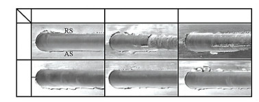
In this review, the weld formation is determined by the surface appearance and defects of the welded joint. The assistant softening effect of ultrasonic vibrations in FSW influences the weld formation[112, 114-118, 135, 139]. Using Mode 1 exertion, Park et al.[112] reported elimination of the weld defects. Ahmadnia et al.[139] observed that a higher vibration power substantially reduced the surface roughness of weld. Liu et al.[118] observed that the groove on the surface of FSW joint was eliminated over a range of welding parameters by using Mode 3 ultrasonic exertion. This improved the surface finish of the joint in UVeFSW, as shown in Fig. 18. Also, the tunnel defect of the FSW joint has disappeared in the UVeFSW joint, as shown in Fig. 19. The transverse weld micrographs in Fig. 20 show that presence of the leading ultrasonic vibrations in FSW increase the deformed area of the joint and inhibit the formation of the tunnel defect[118] irrespective of the examined welding parameters. To sum up, ultrasonic vibrations in FSW prevents the formation of the groove, void, tunnel[118, 121] and root flaw defect in the weld nugget[133]. This is attributed to an improved plastic region and material flow due to ultrasonic induced heating[139]. From the above, it is clear that ultrasonic vibrations improve the weld formation. These high-frequency vibrations also influence the thermal history and plastic deformation of the material, i.e., the thermomechanical history of the process. The improved weld formation is a result of the ultrasonically induced variations in thermomechanical action.
|
Figure 18 Welds appearance comparison in FSW and UVeFSW[118] |

|
Figure 19 Weld X-ray films comparison in FSW and UVeFSW[118] |

|
Figure 20 Traverse cross sections of weld profiles comparison in FSW and UVeFSW[118] |
5.5 Microstructure of Welded Joints
The thermomechanical action of the FSW tool varies from location to location in the workpiece. This induces a microstructure inhomogeneity in the welded joint. Based on the microstructure, FSW joint can be classified into four different zones, namely weld nugget zone (WNZ) or stir zone (SZ), thermo-mechanically affected zone (TMAZ), heat affected zone (HAZ) and base material zone (BMZ). Since the assisting ultrasonic vibrations exert a considerable effect on the temperature and deformation history[128], they can also influence the weld microstructure.
Padhy et al. [119] carried out a comparative study of microstructure evolution in the FSW nugget of AA 6061-T6 with and without the Mode 3 ultrasonic exertion. Fig. 21 shows orientation maps of different locations of weld nugget centre and weld nugget boundary of the AA 6061-T6 in FSW and UVeFSW. The maps in Fig. 21(a) to (d) are associated with depths 0.5, 2.5, 4.0 and 5.5 mm of the weld nugget at the centre line. With ultrasonic vibrations, the continuous recrystallization was improved, the grain orientation was varied from (111) to (101) and grain refinement was increased. The effect of ultrasonic vibrations on grain refinement was found to be maximum in the middle of the weld and decreased gradually towards the boundaries. Further, the ultrasonic vibrations caused an increase in the complete recrystallization (grains with misorientation >45°), strain field and subgrain formation[140-142]. Interestingly, the maxima of complete recrystallization[140], ultrasonic induced subgrain formation[141] and strain field[142] were found at those locations which experienced the maximum ultrasonic effect. The higher strain field also contributed to the grain refinement[142]. The increase in the above crystallographic features of weld nugget with ultrasonic vibrations is directly related to the increase in plastic deformation which is a result of the release of blocked dislocations and their increased mobility at the higher strain rate[119, 136].

|
Figure 21 Orientation maps of weld nugget centre of at different depth |
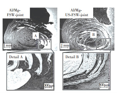
Tarasov et al.[122], using Mode 5 ultrasonic exertion in FSW, studied the microstructure evolution of welded joint of Al-Cu-Li-Mg alloy. With the ultrasonic vibration, grain refinement and dissolution of strain induced soluble and insoluble intermetallic precipitates were facilitated. This improved the precipitation of coherent metastable phases and recrystallization of a solid solution. Using the same method, Eliseev et al.[125] investigated the microstructure and properties of AA2024 joint. An increased tool stirring due to decreasing cross-sectional area of macropores in the stir zone was reported. Besides, recrystallized grains were generated in the TMAZ due to the acoustoplastic effect which improved the zone structurally. Using Mode 4 ultrasonic exertion, Strass et al.[108] studied the microstructure of dissimilar Al/Mg joint. It was observed that the presence of the lateral ultrasonic vibrations generates an intense stir zone and eliminates an intermetallic compound layer, as shown in Fig. 22[108, 111, 124].
|
Figure 22 Al/Mg joint cross-section with/without ultrasonic vibration[108] |
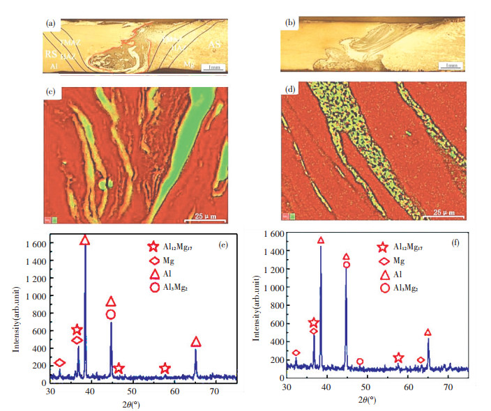
Recently, Ji et al. [143] conducted ultrasonic assisted FSW of Al alloy to Mg alloy using Mode 5 exertion. With the vibrations in FSW, the material intermixing in the nugget zone was increased. The intermetallic compounds (IMCs) distribution in the Al/Mg interface was improved due to the breakage of partial IMCs into pieces. The vibrations also enhanced mechanical interlocking at the joint interface. Ultimately, the above changes caused improvement in joint strength, as shown in Fig. 23. Further, Lv et al.[120] found that the IMC bi-layer (Al12Mg17 +Al3Mg2) formed at the Al/Mg interface diminishes into monolayers using Mode 3 vibrations and proper tool offset, thus, decreasing the overall thickness of the IMC layer. A tool offset on Mg side generated the Mg-rich Al12Mg17 monolayer and that on Al side created the Al-rich Al3Mg2 monolayer. The intermetallic layer was completely removed using a higher ultrasonic power[120]. In summary, the assisting ultrasonic vibrations improved the microstructure of welded joints in FSW. The microstructure is closely related to the mechanical properties. Therefore, it is interesting to review the effects of ultrasonic vibrations on the mechanical properties of FSW joints.
|
Figure 23 Macrostructures (a) with ultrasonic (b) without ultrasonic; distribution map of Al/Mg elements (c) with ultrasonic (d) without ultrasonic; XRD patterns (e) with ultrasonic (f) without ultrasonic[143] |
5.6 Mechanical Properties of the Joints
Using Mode 1 exertion, Park et al.[112, 127] observed that the yield strength and elongation of welded joints of AA 6061-T6 increase by 10% and 15%, as shown in the stress-strain curve in Fig. 24. In a separate study, similar observations in AA 6061-T6 joints are reported by Amini et al[128]. Using ultrasonic vibrations, they reported 10%, 10% and 15% increase in tensile strength, elongation and hardness, respectively.

|
Figure 24 Welded joint tensile test stress-strain relationship at different welding parameters[127] |
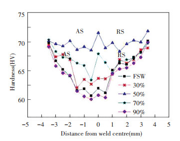
Rostamiyan et al.[144] studied the effect of ultrasonic vibration on lap shear force and hardness of friction stir spot welded AA6061. With ultrasonic vibrations, the spot welded joints achieved higher lap shear force and hardness. Using the Mode 1 ultrasonic exertion, Ahmadinia et al.[139] studied the effect of ultrasonic power on the welded joints of AA6061. It was found that ultrasonic power exerts a significant influence on the mechanical and tribological properties. With vibrations, the welds exhibited higher tensile strength and Erichsen number. Increasing ultrasonic power caused a reduction in surface roughness and tool wear rate[139]. In other words, the exerted vibrations enhanced the mechanical and tribological properties of the welded joint. This study also revealed that the hardness and tensile strength of the spot welded AA 6061 joint increase up to an ultrasonic power output 50%, as depicted in Figs. 25 and 26[138]. Beyond this, a reduction in hardness was observed. In contrast, the elongation reduced with increasing ultrasonic power.
|
Figure 25 Influence of ultrasonic vibration powers on Hardness[138] |
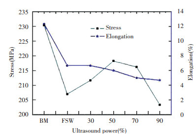
|
Figure 26 Influence of ultrasonic vibration power on tensile strength and elongations[138] |
The microhardness of friction stir welded AA 2024-T4 joint using Mode 3 exertion was higher than that without the vibrations, as shown in Fig. 27. Also, the presence of vibrations caused microhardness minima on the AS and RS to move further away from the weld nugget[118]. In the same study, tensile strength and elongations of the welded joints were improved with ultrasonic vibration, as shown in Fig. 28(a). At welding speed 100 mm/min, the tensile strength of FSW joint dropped suddenly while that of UVeFSW joint remained constant. This is because of a small tunnel defect in FSW joint which was absent in the UVeFSW joint. At welding speed 120 mm/min, the FSW joint failed instantaneously due to a larger defect while the UVeFSW joint showed a lower strength because of a much smaller defect. Similarly, the elongation of the welded joint also improved in the presence of ultrasonic vibrations, as shown in Fig. 28(b). Therefore, ultrasonic vibrations in FSW improve the hardness, tensile strength, and elongation of welded joints. It is known that the main strengthening factors in the welded joints of aluminium alloys are the precipitates or second-phase particles in the stir zone. Also, the higher grain refinement caused by ultrasonic vibrations would also contribute towards the improvement of mechanical properties[139].

|
Figure 27 Microhardness distribution in FSW and UVeFSW joints (800 r/min, 80 mm/min, ΔZ = 0.05 mm)[118] |
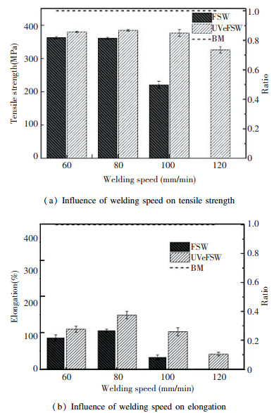
|
Figure 28 Influence of welding speed on tensile strength and elongation (800 r /min, ΔZ = 0.05 mm)[118] |
A recent investigation on dispersion hardened AA2024 alloy[145] found that nano-sized Al2MgCu (S-phase) platelets were the dominant precipitate phase in the stir zone of UVAFSW while fine spherical AlMgCu precipitates were abundant in the FSW joint. The predominance of nano-sized coherent S-phase in the joint with ultrasonic vibrations caused the improvement in weld mechanical properties. In a similar study on dispersion hardened AA7475 alloy, the higher microhardness and joint strength of welded joint in the presence of ultrasonic vibrations[146] is ascribed to the coherent T- and S-phase particles which are thought to be formed by ultrasonic induced modification of precipitation kinetics of tertiary phase[147]. Ultrasonic vibrations also improved the mechanical properties of dissimilar joints. In the presence of ultrasonic vibrations, the weld tensile strength was enhanced by up to 30% in the dissimilar FSW of AA5454 to AZ91D[111], AA 6061-T4 to AZ31B-H24 Mg[124] and AA6061-T6 to AZ31B[143].The improvement in mechanical properties of the dissimilar joints in the presence of ultrasonic vibrations can be attributed to the increased degree of intermixing, mechanical interlocking[143] and reduction in IMC layer of the joints[138].
5.7 Fracture Surface of the FSW JointMa et al. [138] studied the fracture pattern and its origin in the friction stir welded joints with and without ultrasonic vibrations. The fracture surfaces at various depths of the weld were different and they varied further in the presence of ultrasonic vibrations. The fracture mode appeared to be predominantly ductile dimple pattern in the presence of ultrasonics while it was less ductile in the absence of vibrations. The above study suggested that the fracture was initiated at a slip band at the top and propagated to the bottom[138]. Applying the Mode 4 ultrasonic exertion, Liu et al.[118] found that the fracture in the welded joint of AA 2024-T4 was located within the weld nugget in FSW and at the TMAZ-HAZ interface in UVeFSW. The fracture locations of the welded joints with and without the vibrations are shown in Fig. 29 and the fracture surfaces are shown in Fig. 30. The fracture surface of FSW joint exhibited an intergranular failure characterized by dimples (Fig. 30(a)) while that in the UVeFSW showed a brittle ductile mixed transgranular fracture (Fig. 30(b)). The bottom of the dimples in the ultrasonically enhanced joint constituted ruptured second phase particles, indicating a strong bond between the precipitate and the matrix which improved weld mechanical properties[134]. Rostamiyan et al.[144] investigated the fracture surface of an ultrasonically assisted friction stir spot welded Al 6061 joint. They reported that a finer and uniform distribution of grains with more grain boundaries increased the lap shear strength of the joint with ultrasonic vibrations.
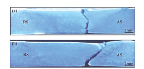
|
Figure 29 Fracture position of FSW and UVeFSW joints at welding parameters (800-80-0.05)[118] |
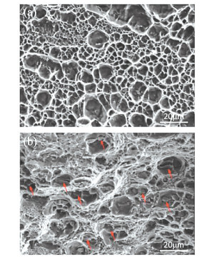
|
Figure 30 SEM microstructure of fracture surface of the alloy at welding parameters (800-80-0.05)[118] |
Table 1 provides a quick checklist of the materials and process parameters used in the reported studies on ultrasonic vibration assisted FSW process.
| Table 1 Checklist of materials and process parameters used in the reported studies on ultrasonic assisted FSW |
6 Conclusions
1) This paper provides a compiled review on the progress of ultrasonic vibration assisted FSW processes. The influence of ultrasonic vibrations on the process effectiveness and quality of the welded joint reported in various studies have been presented and analyzed.
2) Ultrasonic vibration as an assistant energy source in FSW preserves the very sustainability of the original process and presents multiple advantages over the other assistant energy sources. Application of ultrasonic vibrations in FSW reduce the welding loads, improve the thermal history, enhance the plasticization, flow and intermixing of material. These ultrasonic induced effects are reciprocated into the welded joint, producing improved results in terms of weld formation, microstructure, mechanical and tribological properties.
3) The above ultrasonic effects improve the life and performance of tool and widen the window of safe process parameters which would reduce the number of experiments and thus, save both time and money.
4) To model this process into a candidate for industrial application, a complete understanding of the underlying physics of the process is mandatory. This can be achieved by conducting studies on the mode of ultrasonic exertion, experimental investigations with high strength structural materials and modelling and simulation of the process.
5) Although there exist some documented reports on the numerical modelling of some aspects of the ultrasonically assisted FSW process, they are not adequate to formulate generalization. Therefore, progresses must be made towards the development of numerical process models and upgradation of technology to make these processes compatible and robust to industry culture. More studies on design, modelling and application of this process are expected in subsequent years.
| [1] |
Padhy G K, Wu C S, Gao S. Friction stir based welding and processing technologies processes, parameters, microstructures and applications: A review. Journal of Materials Science and Technology, 2018, 34: 1-38. DOI:10.1016/j.jmst.2017.11.029 ( 0) 0)
|
| [2] |
Mishra R S, Ma Z Y. Friction stir welding and processing. Materials Science and Engineering R: Reports. 2005, 50(1-2) : 1-78. DOI: 10.1016/j.mser.2005.07.001.
( 0) 0)
|
| [3] |
Thomas W M, Norris I M, Nicholas E D, et al. Friction stir welding process developments and variant techniques. 1991. http://www.google.com/patents/US5460317%5Cn.
( 0) 0)
|
| [4] |
Dawes C, Thomas W. Friction Stir Joining of Aluminium Alloys, TWI Bulletin 6. 1995. 124-127.
( 0) 0)
|
| [5] |
Nandan R, DebRoy T, Bhadeshia H K D H. Recent advances in friction-stir welding-Process, weldment structure and properties. Progress in Materials Science, 2008, 53(6): 980-1023. DOI:10.1016/j.pmatsci.2008.05.001 ( 0) 0)
|
| [6] |
Khairuddin J T, Abdullah J, Hussain Z, et al. Principles and Thermo-Mechanical Model of Friction Stir Welding. Crotia: INTECH Open Access Publisher, 2012. DOI:10.5772/50156
( 0) 0)
|
| [7] |
Groover M P. Modern Manufacturing, 2011. DOI: 10.1007/978-3-319-20152-8.
( 0) 0)
|
| [8] |
Guo J. Solid State Welding Processes in Manufacturing, HandBook of Manufacturing Engineering and Technology. 2015. 3405-3435. doi: 10.1007/978-1-4471-4670-4.
( 0) 0)
|
| [9] |
Mishra R S, Mahoney M W. Friction Stir Welding and Processing. Ohio: ASM International, 2007, 368.
( 0) 0)
|
| [10] |
Mishra R S, Mahoney M W. Friction Stir Welding and Processing. Russel: ASM Internation, 2007, 7-35.
( 0) 0)
|
| [11] |
Rowe C E D, Thomas W M. Advances in tooling materials for friction stir welding. http://www.innovaltec.com/downloads/rowe_matcong.pdf.
( 0) 0)
|
| [12] |
Neto D M, Neto P. Numerical modeling of friction stir welding process: A literature review. The International Journal of Advanced Manufacturing Technology, 2013, 65(1-4): 115-126. DOI:10.1007/s00170-012-4154-8 ( 0) 0)
|
| [13] |
Liu H J, Fujii H, Maeda M, et al. Tensile fracture location characterizations of friction stir welded joints of different aluminum alloys. Strain, 2004, 20: 103-105. ( 0) 0)
|
| [14] |
Khaled T. An outsider looks at friction stir welding. Fed Aviat Admin, 2005, 90712: 1-71. ( 0) 0)
|
| [15] |
Rai R, De A, Bhadeshia H K D H, et al. Review: Friction stir welding tools. Science and Technology of Welding and Joining, 2011, 16(4): 325-342. DOI:10.1179/1362171811Y.0000000023 ( 0) 0)
|
| [16] |
Elangovan K, Balasubramanian V, Babu S. Developing an empirical relationship to predict tensile strength of friction stir welded AA2219 aluminum alloy. Journal of Materials Engineering and Performance, 2008, 17(6): 820-830. DOI:10.1007/s11665-008-9240-6 ( 0) 0)
|
| [17] |
He X C, Gu F S, Ball A. A review of numerical analysis of friction stir welding. Progress in Materials Science, 2014, 65: 1-66. DOI:10.1016/j.pmatsci.2014.03.003 ( 0) 0)
|
| [18] |
Elangovan K, Balasubramanian V, Babu S. Predicting tensile strength of friction stir welded AA6061 aluminium alloy joints by a mathematical model. Materials and Design, 2009, 30(1): 188-193. DOI:10.1016/j.matdes.2008.04.037 ( 0) 0)
|
| [19] |
Silva A C F, Braga D F O, de Figueiredo M A V, et al. Ultimate tensile strength optimization of different FSW aluminium alloy joints. International Journal of Advanced Manufacturing Technology, 2015, 79(5-8): 805-814. DOI:10.1007/s00170-015-6871-2 ( 0) 0)
|
| [20] |
Dursun T, Soutis C. Recent developments in advanced aircraft aluminium alloys. Materials and Design, 2014, 56: 862-871. DOI:10.1016/j.matdes.2013.12.002 ( 0) 0)
|
| [21] |
Lertora E, Gambaro C. AA8090 Al-Li Alloy FSW parameters to minimize defects and increase fatigue life. International Journal of Material Forming, 2010, 3: 1003-1006. DOI:10.1007/s12289-010-0939-1 ( 0) 0)
|
| [22] |
Liu H J, Zhang H J, Pan Q, et al. Effect of friction stir welding parameters on microstructural characteristics and mechanical properties of 2219-T6 aluminum alloy joints. International Journal of Material Forming, 2012, 5(3): 235-241. DOI:10.1007/s12289-011-1048-5 ( 0) 0)
|
| [23] |
Buffa G, Campanile G, Fratini L, et al. Friction stir welding of lap joints: Influence of process parameters on the metallurgical and mechanical properties. Materials Science and Engineering A, 2009, 519(1-2): 19-26. DOI:10.1016/j.msea.2009.04.046 ( 0) 0)
|
| [24] |
Threadgill P L, Leonard A J, Shercliff H R, et al. Friction stir welding of aluminium alloys. International Materials Reviews, 2009, 54(2): 49-93. DOI:10.1179/174328009X411136 ( 0) 0)
|
| [25] |
Uyyuru R K, Kailas S V. Numerical analysis of friction stir welding process. Journal of Materials Engineering and Performance, 2013, 22(10): 2921-2934. DOI:10.1007/s11665-013-0729-2 ( 0) 0)
|
| [26] |
Mishra R S, De P S, Kumar N. Friction Stir Welding and Processing:Science and Engineering. Berlin: Springer, 2014. DOI:10.1007/978-3-319-07043-8
( 0) 0)
|
| [27] |
Thomas W M, Nicholas E D. Friction stir welding for the transportation industries. Materials & Design, 1997, 18(4-6): 269-273. DOI:10.1016/S0261-3069(97)00062-9 ( 0) 0)
|
| [28] |
Kallee S W. Friction Stir Welding, 2010. 118-163. DOI: 10.1533/9781845697716.1.118.
( 0) 0)
|
| [29] |
Çam G, Mistikoglu S. Recent developments in friction stir welding of AL-alloys. Journal of Materials Engineering and Performance, 2014, 23(6): 1936-1953. DOI:10.1007/s11665-014-0968-x ( 0) 0)
|
| [30] |
TWI Ltd. Friction stir welding the next generation of lightweight vehicles. http://www.twi-global.com/news-events/case-studies/friction-stir-welding-the-next-generation-of-lightweight-vehicle-646. (Accessed 15 April 2017).
( 0) 0)
|
| [31] |
Ding J, Carter R, Lawless K, et al. Friction stir welding flies high at NASA. Welding Journal, 2006, 85(3): 54-59. ( 0) 0)
|
| [32] |
Gibson B T, Lammlein D H, Prater T J, et al. Friction stir welding: Process, automation, and control. Journal of Manufacturing Processes, 2014, 16(1): 56-73. DOI:10.1016/j.jmapro.2013.04.002 ( 0) 0)
|
| [33] |
Li W Y, Fu T, Hütsch L, et al. Effects of tool rotational and welding speed on microstructure and mechanical properties of bobbin-tool friction-stir welded Mg AZ31. Materials and Design, 2014, 64: 714-720. DOI:10.1016/j.matdes.2014.07.023 ( 0) 0)
|
| [34] |
Kumar B A, Murugan N. Optimization of friction stir welding process parameters to maximize tensile strength of stir cast AA6061-T6/AlNp composite. Materials & Design, 2014, 57: 383-393. DOI:10.1016/j.matdes.2013.12.065 ( 0) 0)
|
| [35] |
Kumar K, Kailas S V. The role of friction stir welding tool on material flow and weld formation. Materials Science and Engineering A-Structural Materials Properties Microstructure and Processing, 2008, 485(1-2): 367-374. DOI:10.1016/j.msea.2007.08.013 ( 0) 0)
|
| [36] |
Kim Y G, Fujii H, Tsumura T, et al. Three defect types in friction stir welding of aluminum die casting alloy. Materials Science and Engineering A-Structural Materials Properties Microstructure and Processing, 2006, 415(1-2): 250-254. DOI:10.1016/j.msea.2005.09.072 ( 0) 0)
|
| [37] |
Chen H B, Yan K, Lin T, et al. The investigation of typical welding defects for 5456 aluminum alloy friction stir welds. Materials Science and Engineering A -Structural Materials Properties Microstructure and Processing, 2006, 433(1-2): 64-69. DOI:10.1016/j.msea.2006.06.056 ( 0) 0)
|
| [38] |
Tutum C C, Hattel J H. Numerical optimisation of friction stir welding: Review of future challenges. Science and Technology of Welding and Joining, 2011, 16(4): 318-324. DOI:10.1179/1362171811Y.0000000011 ( 0) 0)
|
| [39] |
Kohn G, Greenberg Y, Makover I, et al. Laser-assisted friction stir welding. Welding Journal, 2002, 81(2): 46-48. ( 0) 0)
|
| [40] |
Arora A, Mehta M, De A, et al. Load bearing capacity of tool pin during friction stir welding. International Journal of Advanced Manufacturing Technology, 2012, 61(9-12): 911-920. DOI:10.1007/s00170-011-3759-7 ( 0) 0)
|
| [41] |
Lutjering G, Williams J C. Titanium: Engineering Materials and Processes. (2nd ed. ) Berlin: Springer. 2007. 1-442. DOI: 10.1007/978-3-540-73036-1.
( 0) 0)
|
| [42] |
Sanders D G, Ramulu M, Edwards P D. Superplastic forming of friction stir welds in titanium alloy 6Al-4V: Preliminary results. Materialwissenschaft Und Werkstofftechnik, 2008, 39(4-5): 353-357. DOI:10.1002/mawe.200800305 ( 0) 0)
|
| [43] |
Meran C, Kovan V, Alptekin A. Friction stir welding of AISI 304 austenitic stainless steel. Materialwissenschaft Und Werkstofftechnik, 2007, 38(10): 829-835. DOI:10.1002/mawe.200700214 ( 0) 0)
|
| [44] |
Russell M J, Blignault C, Horrex N L, et al. Recent developments in the friction stir welding of titanium alloys. Welding in the World, 2008, 52: 12-15. DOI:10.1007/BF03266662 ( 0) 0)
|
| [45] |
Cam G. Friction stir welded structural materials: Beyond Al-alloys. International Materials Reviews, 2011, 56(1): 1-48. DOI:10.1179/095066010X12777205875750 ( 0) 0)
|
| [46] |
Thomas W M, Threadgill P L, Nicholas E D. Feasibility of friction stir welding steel. Science and Technology of Welding and Joining, 1999, 4(6): 365-372. DOI:10.1179/136217199101538012 ( 0) 0)
|
| [47] |
Russell M J, Blignault C, Horrex N L, et al. Recent Developments in the Friction Stir Welding of Titanium Alloys. Welding in the World, 2013, 52(9-10): 12-15. DOI:10.1007/BF03266662 ( 0) 0)
|
| [48] |
Salih O S, Ou H G, Sun W, et al. A review of friction stir welding of aluminium matrix composites. Materials & Design, 2015, 86: 61-71. DOI:10.1016/j.matdes.2015.07.071 ( 0) 0)
|
| [49] |
Chen T. Process parameters study on FSW joint of dissimilar metals for aluminum-steel. Journal of Materials Science, 2009, 44(10): 2573-2580. DOI:10.1007/s10853-009-3336-8 ( 0) 0)
|
| [50] |
Chen X G, da Silva M, Gougeon P, et al. Microstructure and mechanical properties of friction stir welded AA6063-B4C metal matrix composites. Materials Science and Engineering A-Structural Materials Properties Microstructure and Processing, 2009, 518(1-2): 174-184. DOI:10.1016/j.msea.2009.04.052 ( 0) 0)
|
| [51] |
DebRoy T, Bhadeshia H K D H. Friction stir welding of dissimilar alloys-a perspective. Science and Technology of Welding & Joining, 2010, 15: 266-270. DOI:10.1179/174329310X12726496072400 ( 0) 0)
|
| [52] |
Thomas W M. Friction stir welding - Recent developments. Materials Science Forum, 2003, 426-432: 229-236. DOI:10.4028/www.scientific.net/MSF.426-432 ( 0) 0)
|
| [53] |
Bhadeshia H K D H, DebRoy T. Critical assessment: Friction stir welding of steels. Science and Technology of Welding and Joining, 2009, 14(3): 193-196. DOI:10.1179/136217109X421300 ( 0) 0)
|
| [54] |
Thomas W M, Staines D G, Norris I M, et al. Friction stir welding tools and developments. Welding in the World, 2003, 47: 10-17. DOI:10.1007/BF03266403 ( 0) 0)
|
| [55] |
Zhang Y N, Cao X, Larose S, et al. Review of tools for friction stir welding and processing. Canadian Metallurgical Quarterly, 2012, 51(3): 250-261. DOI:10.1179/1879139512Y.0000000015 ( 0) 0)
|
| [56] |
Mehta M, Arora A, De A, et al. Tool geometry for friction stir welding-Optimum shoulder diameter. Metallurgical and Materials Transactions A: Physical Metallurgy and Materials Science, 2011, 42A(9): 2716-2722. DOI:10.1007/s11661-011-0672-5 ( 0) 0)
|
| [57] |
Collier M, Steel R, Nelson T W, et al. Grade development of polycrystalline cubic boron nitride for friction stir processing of ferrous alloys. Materials Science Forum, 2003, 426-432: 3011-3016. DOI:10.4028/www.scientific.net/MSF.426-432.3011 ( 0) 0)
|
| [58] |
Zhang Y, Sato Y S, Kokawa H, et al. Stir zone microstructure of commercial purity titanium friction stir welded using pcBN tool. Materials Science and Engineering A -Structural Materials Properties Microstructure and Processing, 2008, 488(1-2): 25-30. DOI:10.1016/j.msea.2007.10.062 ( 0) 0)
|
| [59] |
Fujii H, Cui L, Tsuji N, et al. Friction stir welding of carbon steels. Materials Science and Engineering A, 2006, 429: 50-57. DOI:10.1016/j.msea.2006.04.118 ( 0) 0)
|
| [60] |
Cui L, Fujii H, Tsuji N, et al. Friction stir welding of a high carbon steel. Scripta Materialia, 2007, 56(7): 637-640. DOI:10.1016/j.scriptamat.2006.12.004 ( 0) 0)
|
| [61] |
Saeid T, Abdollah-zadeh A, Assadi H, et al. Effect of friction stir welding speed on the microstructure and mechanical properties of a duplex stainless steel. Materials Science and Engineering A-Structural Materials Properties Microstructure and Processing, 2008, 496(1-2): 262-268. DOI:10.1016/j.msea.2008.05.025 ( 0) 0)
|
| [62] |
Azuma Y, Kameno Y, Takasugi T. Friction stir welding in stainless steel sheet of type 430 using Ni-based dual two-phase intermetallic alloy tool. Welding International, 2013, 27: 929-935. DOI:10.1080/09507116.2012.715878 ( 0) 0)
|
| [63] |
Sato Y S, Nagahama Y, Mironov S, et al. Microstructural studies of friction stir welded zircaloy-4. Scripta Materialia, 2012, 67(3): 241-244. DOI:10.1016/j.scriptamat.2012.04.029 ( 0) 0)
|
| [64] |
Ohashi R, Fujimoto M, Mironov S, et al. Effect of contamination on microstructure in friction stir spot welded DP590 steel. Science and Technology of Welding and Joining, 2009, 14(3): 221-227. DOI:10.1179/136217108X388642 ( 0) 0)
|
| [65] |
Ishikawa T, Fujii H, Genchi K, et al. High Speed - High Quality Friction Stir Welding of Austenitic. 2009, 49 (6) : 897-901. DOI: 10.2355/isijinternational.49.897.
( 0) 0)
|
| [66] |
Sun Y F, Fujii H, Takaki N, et al. Microstructure and mechanical properties of mild steel joints prepared by a flat friction stir spot welding technique. Materials and Design, 2012, 37: 384-392. DOI:10.1016/j.matdes.2012.01.027 ( 0) 0)
|
| [67] |
Martinho R P, Silva F J G, Baptista A P M. Wear behaviour of uncoated and diamond coated Si3N4 tools under severe turning conditions. Wear, 2007, 263: 1417-1422. DOI:10.1016/j.wear.2007.01.048 ( 0) 0)
|
| [68] |
Miyazawa T, Iwamoto Y, Maruko T, et al. Development of Ir based tool for friction stir welding of high temperature materials. Science and Technology of Welding and Joining, 2011, 16(2): 188-192. DOI:10.1179/1362171810Y.0000000025 ( 0) 0)
|
| [69] |
Miyazawa T, Iwamoto Y, Maruko T, et al. Development of high strength Ir based alloy tool for friction stir welding. Science and Technology of Welding and Joining, 2012, 17(3): 213-218. DOI:10.1179/1362171811Y.0000000097 ( 0) 0)
|
| [70] |
Fujii H, Sun Y F, Kato H. Microstructure and mechanical properties of friction stir welded pure Mo joints. Scripta Materialia, 2011, 64(7): 657-660. DOI:10.1016/j.scriptamat.2010.12.014 ( 0) 0)
|
| [71] |
Arora A, De A, Debroy T. Toward optimum friction stir welding tool shoulder diameter. Scripta Materialia, 2011, 64(1): 9-12. DOI:10.1016/j.scriptamat.2010.08.052 ( 0) 0)
|
| [72] |
De P S, Mishra R S. Friction stir welding of precipitation strengthened aluminium alloys: Scope and challenges. Science and Technology of Welding and Joining, 2011, 16(4): 343-347. DOI:10.1179/1362171811Y.0000000020 ( 0) 0)
|
| [73] |
Dawes C J, Thomas W M. Friction stir process welds aluminum alloys. Welding Journal, 1996, 75(3): 41-45. ( 0) 0)
|
| [74] |
Uday M B, Fauzi M N A, Zuhailawati H, et al. Advances in friction welding process: A review. Science and Technology of Welding and Joining, 2010, 15(7): 534-558. DOI:10.1179/136217110X12785889550064 ( 0) 0)
|
| [75] |
Millers M P, Decker B J, Nelson T W. Formability and strength of friction-stir-welded aluminum sheets. Metallurgical and Materials Transactions A, 2004, 35: 3461-3468. DOI:10.1007/s11661-004-0183-8 ( 0) 0)
|
| [76] |
Murr L E. A review of FSW research on dissimilar metal and alloy systems. Journal of Materials Engineering and Performance, 2010, 19(8): 1071-1089. DOI:10.1007/s11665-010-9598-0 ( 0) 0)
|
| [77] |
Padhy G K, Wu C S, Gao S. Auxiliary energy assisted friction stir welding-status review. Science and Technology of Welding and Joining, 2015, 20: 1362171815Y. DOI:10.1179/1362171815Y.0000000048 ( 0) 0)
|
| [78] |
Merklein M, Giera A. Laser assisted Friction Stir Welding of drawable steel-aluminium tailored hybrids. International Journal of Material Forming, 2008, 1: 1299-1302. DOI:10.1007/s12289-008-0141-x ( 0) 0)
|
| [79] |
Casalino G, Campanelli S L, Contuzzi N, et al. Laser-assisted friction stir welding of aluminum alloy lap joints: Microstructural and microhardness characterizations. Proceedings of SPIE - The International Society for Optical Engineering. San Francisco:SPIE Lase, 2014. DOI:10.1117/12.2042215 ( 0) 0)
|
| [80] |
Sun Y F, Shen J M, Morisada Y, et al. Spot friction stir welding of low carbon steel plates preheated by high frequency induction. Materials and Design, 2014(54): 450-457. DOI:10.1016/j.matdes.2013.08.071 ( 0) 0)
|
| [81] |
Álvarez A I, García M, Pena G, et al. Evaluation of an induction-assisted friction stir welding technique for super duplex stainless steels. Surface and Interface Analysis, 2014, 46: 892-896. DOI:10.1002/sia.5442 ( 0) 0)
|
| [82] |
Luo J, Chen W, Fu G. Hybrid-heat effects on electrical-current aided friction stir welding of steel, and Al and Mg alloys. Journal of Materials Processing Technology, 2014, 214(12): 3002-3012. DOI:10.1016/j.jmatprotec.2014.07.005 ( 0) 0)
|
| [83] |
Liu X, Lan S H, Ni J. Electrically assisted friction stir welding for joining Al 6061 to TRIP 780 steel. Journal of Materials Processing Technology, 2015, 219: 112-123. DOI:10.1016/j.jmatprotec.2014.12.002 ( 0) 0)
|
| [84] |
Bang H S, Bang H S, Song H J, et al. Joint properties of dissimilar Al6061-T6 aluminum alloy/Ti-6%Al-4%V titanium alloy by gas tungsten arc welding assisted hybrid friction stir welding. Materials and Design, 2013, 51: 544-551. DOI:10.1016/j.matdes.2013.04.057 ( 0) 0)
|
| [85] |
Bang H, Bang H, Jeon G, et al. Gas tungsten arc welding assisted hybrid friction stir welding of dissimilar materials Al6061-T6 aluminum alloy and STS304 stainless steel. Materials and Design, 2012, 37: 48-55. DOI:10.1016/j.matdes.2011.12.018 ( 0) 0)
|
| [86] |
Yaduwanshi D K, Bag S, Pal S. Effect of preheating in hybrid friction stir welding of aluminum alloy. Journal of Materials Engineering and Performance, 2014, 23(10): 3794-3803. DOI:10.1007/s11665-014-1170-x ( 0) 0)
|
| [87] |
Yaduwanshi D K, Bag S, Pal S. Numerical modeling and experimental investigation on plasma-assisted hybrid friction stir welding of dissimilar materials. Materials & Design, 2016, 92: 166-183. DOI:10.1016/j.matdes.2015.12.039 ( 0) 0)
|
| [88] |
Song K H, Tsumura T, Nakata K. Development of microstructure and mechanical properties in laser-FSW hybrid welded inconel 600. Materials Transactions, 2009, 50(7): 1832-1837. DOI:10.2320/matertrans.M2009058 ( 0) 0)
|
| [89] |
Sun Y F, Konishi Y, Kamai M, et al. Microstructure and mechanical properties of S45C steel prepared by laser-assisted friction stir welding. Materials and Design, 2013, 47: 842-849. DOI:10.1016/j.matdes.2012.12.078 ( 0) 0)
|
| [90] |
Long X, Khanna S K. Modelling of electrically enhanced friction stir welding process using finite element method. Science and Technology of Welding and Joining, 2005, 10(4): 482-487. DOI:10.1179/174329305x46664 ( 0) 0)
|
| [91] |
Santos T G, Miranda R M, Vilaca P. Friction Stir Welding assisted by electrical Joule effect. Journal of Materials Processing Technology, 2014, 214: 2127-2133. DOI:10.1016/j.jmatprotec.2014.03.012 ( 0) 0)
|
| [92] |
Blaha F, Langenecker B. Tensile deformation of zinc crystal under ultrasonic vibration. Naturwissenchaften, 1955, 42: 556. ( 0) 0)
|
| [93] |
Langenecker B. Effects of ultrasound on deformation characteristics of metals. IEEE Transonics on Sonics and Ultrasonics, 1966, SU-13(1): 1-8. ( 0) 0)
|
| [94] |
Balle F. Ultrasonic welding. JOM, 2012, 64(3): 400-400. DOI:10.1007/s11837-012-0261-0 ( 0) 0)
|
| [95] |
Siddiq A, El Sayed T. Acoustic softening in metals during ultrasonic assisted deformation via CP-FEM. Materials Letters, 2011, 65(2): 356-359. DOI:10.1016/j.matlet.2010.10.031 ( 0) 0)
|
| [96] |
Yao Z H, Kim G Y, Faidley L, et al. Effects of superimposed high-frequency vibration on deformation of aluminum in micro/meso-scale upsetting. Journal of Materials Processing Technology, 2012, 212(3): 640-646. DOI:10.1016/j.jmatprotec.2011.10.017 ( 0) 0)
|
| [97] |
Siddiq A, El Sayed T. Ultrasonic-assisted manufacturing processes: Variational model and numerical simulations. Ultrasonics, 2012, 52(4): 521-529. DOI:10.1016/j.ultras.2011.11.004 ( 0) 0)
|
| [98] |
Lum I, Huang H, Chang B H, et al. Effects of superimposed ultrasound on deformation of gold. Journal of Applied Physics, 2009, 105(2). DOI:10.1063/1.3068352 ( 0) 0)
|
| [99] |
Mason W P. Physical acoustics and the properties of solids. The Journal of the Acoustical Society of America, 1956, 28: 1197-1206. DOI:10.1121/1.1908593 ( 0) 0)
|
| [100] |
Siddiq A, El Sayed T. A thermomechanical crystal plasticity constitutive model for ultrasonic consolidation. Computational Materials Science, 2012, 51(1): 241-251. DOI:10.1016/j.commatsci.2011.07.023 ( 0) 0)
|
| [101] |
Kong C Y, Soar R C, Dickens P M. A model for weld strength in ultrasonically consolidated components. Proceedings of the Institution of Mechanical Engineers, Part C: Journal of Mechanical Engineering Science, 2005, 219(1): 83-91. DOI:10.1243/09540605X8315 ( 0) 0)
|
| [102] |
Kong C Y, Soar R C, Dickens P M. Optimum process parameters for ultrasonic consolidation of 3003 aluminium. Journal of Materials Processing Technology, 2004, 146(2): 181-187. DOI:10.1016/j.matprotec.2003.10.016 ( 0) 0)
|
| [103] |
Murakawa M, Jin M. The utility of radially and ultrasonically vibrated dies in the wire drawing process. Journal of Materials Processing Technology, 2001, 113(1-3): 81-86. DOI:10.1016/S0924-0136(01)00635-5 ( 0) 0)
|
| [104] |
Kumar S, Wu C S, Padhy G K, et al. Application of ultrasonic vibrations in welding and metal processing: A status review. Journal of Manufacturing Processes, 2017, 26: 295-322. DOI:10.1016/j.jmapro.2017.02.027 ( 0) 0)
|
| [105] |
Kong C Y, Soar R C, Dickens P M. Characterisation of aluminium alloy 6061 for the ultrasonic consolidation process. Materials Science and Engineering A-Structural Materials Properties Microstructure and Processing, 2003, 363(1-2): 99-106. DOI:10.1016/S0921-5093(03)00590-2 ( 0) 0)
|
| [106] |
Rozenberg L D. Physical Principles of Utrasonic Technology. New York: Springer Science Business Media, LLC, 1973. DOI:10.1007/978-1-4684-82171
( 0) 0)
|
| [107] |
Ashida Y, Aoyama H. Press forming using ultrasonic vibration. Journal of Materials Processing Technology, 2007, 187-188: 118-122. DOI:10.1016/j.jmatprotec.2006.11.174 ( 0) 0)
|
| [108] |
Strass B, Wagner G, Conrad C, et al. Realization of Al/Mg-hybrid-joints by ultrasound supported friction stir welding-nechanical properties, microstructure and corrosion behavior. Advanced Materials Research, 2014, 966-967: 521-535. DOI:10.4028/www.scientific.net/AMR.966-967.521 ( 0) 0)
|
| [109] |
ASM Handbook Committee. Welding Brazing and Soldering. ASM Handbook, 1993, 2873. DOI:10.1017/CBO9781107415324.004 ( 0) 0)
|
| [110] |
Wagner G, Balle F, Eifler D. Ultrasonic welding of hybrid joints. Jom, 2012, 64: 401-406. DOI:10.1007/s11837-012-0269-5 ( 0) 0)
|
| [111] |
Strass B, Wagner G, Conrad C, et al. Realization of Al/Mg-hybrid-joints by ultrasound supported friction stir welding. Advanced Materials Research, 2014, 783-786: 1814-1819. DOI: 10.4028/www.scientific.net/AMR.966-967.521.
( 0) 0)
|
| [112] |
Park K, Kim G, Ni J. Design and analysis of ultrasonic assisted friction stir welding. Proceedings of IMECE2007 2007 ASME International Mechanical Engineering Congress and Exposition. 2007. 1-7.
( 0) 0)
|
| [113] |
Lai R L, He D Q, Liu L C, et al. A study of the temperature field during ultrasonic-assisted friction-stir welding. International Journal of Advanced Manufacturing Technology, 2014, 73(1-4): 321-327. DOI:10.1007/s00170-014-5813-8 ( 0) 0)
|
| [114] |
Zhong Y B, Wu C S, Padhy G K. Effect of ultrasonic vibration on welding load, temperature and material flow in friction stir welding. Journal of Materials Processing Technology, 2017, 239: 279-283. DOI:10.1016/j.jmatprotec.2016.08.025 ( 0) 0)
|
| [115] |
Liu X C, Wu C S, Rethmeier M, et al. Mechanical properties of 2024-T4 aluminium alloy joints in ultrasonic vibration enhanced friction stir welding. China Welding, 2013, 22: 8-13. ( 0) 0)
|
| [116] |
Liu X C, Wu C S. Experimental study on ultrasonic vibration enhanced friction stir welding. Proceedings of the 1st International Joint Symposium on Joining and Welding (Ed. H. Fuji). Oxford: Woodhead Publishing, 2013, 151-154.
( 0) 0)
|
| [117] |
Wu C S, Liu X C. Experimental investigation on the mechanism of ultrasonic vibration enhanced friction stir welding. Proc. 10th Int. Friction Stir Welding Symp, Combridge UK: The Welding Institute, 2014. paper 9A-4.
( 0) 0)
|
| [118] |
Liu X C, Wu C S, Padhy G K. Improved weld macrosection, microstructure and mechanical properties of 2024Al-T4 butt joints in ultrasonic vibration enhanced friction stir welding. Science and Technology of Welding and Joining, 2015, 20(4): 345-352. DOI:10.1179/1362171815Y.0000000021 ( 0) 0)
|
| [119] |
Padhy G K, Wu C S, Gao S, et al. Local microstructure evolution in Al 6061-T6 friction stir weld nugget enhanced by ultrasonic vibration. Materials and Design, 2016, 92: 710-723. DOI:10.1016/j.matdes.2015.12.094 ( 0) 0)
|
| [120] |
Lv X Q, Wu C S, Padhy G K. Diminishing intermetallic compound layer in ultrasonic vibration enhanced friction stir welding of aluminum alloy to magnesium alloy. Materials Letters, 2017, 203: 81-84. DOI:10.1016/j.matlet.2017.05.090 ( 0) 0)
|
| [121] |
Shi L, Wu C S, Liu X C. Modeling the effects of ultrasonic vibration on friction stir welding. Journal of Materials Processing Technology, 2015, 222: 91-102. DOI:10.1016/j.jmatprotec.2015.03.002 ( 0) 0)
|
| [122] |
Tarasov K E, Yu S, Rubtsov V E, et al. The ultrasonic-assisted aging in friction stir welding on Al-Cu-Li-Mg aluminum alloy. Weld World, 2017. DOI:10.1007/s40194-017-0447-8 ( 0) 0)
|
| [123] |
Liu X C, Wu C S, Padhy G K. Characterization of plastic deformation and material flow in ultrasonic vibration enhanced friction stir welding. Scripta Materialia, 2015, 102: 95-98. DOI:10.1016/j.scriptamat.2015.02.022 ( 0) 0)
|
| [124] |
Thomä M, Wagner G, Straß B, et al. Recent developments for ultrasonic-assisted friction stir welding: Joining, testing, corrosion-an overview. IOP Conf erence Series: Materials Science and Engineering, 2016, 118: 8. DOI: 10.1088/1757-899X/118/1/012014.
( 0) 0)
|
| [125] |
Eliseev A, Tarasov S, Fortuna S, et al. Effect of ultrasonic application during friction stir welding on microstructure and properties of AA2024 fixed joints. Key Engineering Materials, 2016, 683: 227-231. DOI:10.4028/www.scientific.net/KEM.683.227 ( 0) 0)
|
| [126] |
Park K, Kim B, Ni J. Numerical simulation of plunge force during the plunge phase of- imece2008-6 7002. Proceedings of IMECE2008 2008 ASME International Mechanical Engineering Congress and Exposition. 2008. 1-6.
( 0) 0)
|
| [127] |
Park K. Development and Analysis of Ultrasonic Assisted Friction Stir Welding Process. Ann Arbor, MI: The University of Michigan, 2009.
( 0) 0)
|
| [128] |
Amini S, Amiri M R. Study of ultrasonic vibrations' effect on friction stir welding. The International Journal of Advanced Manufacturing Technology, 2014, 73(1-4): 127-135. DOI:10.1007/s00170-014-5806-7 ( 0) 0)
|
| [129] |
Kumar S. Ultrasonic assisted friction stir processing of 6063 aluminum alloy. Archives of Civil and Mechanical Engineering, 2016, 16(3): 473-484. DOI:10.1016/j.acme.2016.03.002 ( 0) 0)
|
| [130] |
Montazerolghaem H, Badrossamay M, Tehrani A F. Investigation of vibration assisted friction stir welding. Key Engineering Materials, 2012, 504-506: 741-746. DOI:10.4028/www.scientific.net/KEM.504-506.741 ( 0) 0)
|
| [131] |
Amini S, Nazari M M, Rezaei A. Bending vibrational tool for friction stir welding process. International Journal of Advanced Manufacturing Technology, 2016, 84(9-12): 1889-1896. DOI:10.1007/s00170-015-7834-3 ( 0) 0)
|
| [132] |
Aval H J, Serajzadeh S, Kokabi A H. Theoretical and experimental investigation into friction stir welding of AA 5086. International Journal of Advanced Manufacturing Technology, 2011, 52(5-8): 531-544. DOI:10.1007/s00170-010-2752-x ( 0) 0)
|
| [133] |
Tarasov S Y, Rubtsov V Y, Kolubaev E A, et al. Ultrasonic-assisted friction stir welding on V95AT1 (7075) aluminum alloy. International Conference on Advanced Materials with Hierarchical Structure for New Technologies and Reliable Structures 2015. 2015, 1683: 20231. DOI: 10.1063/1.4932921.
( 0) 0)
|
| [134] |
Liu X C, Wu C S. Material flow in ultrasonic vibration enhanced friction stir welding. Journal of Materials Processing Technology, 2015, 225: 32-44. DOI:10.1016/j.jmatprotec.2015.05.020 ( 0) 0)
|
| [135] |
Liu X C, Wu C S. Elimination of tunnel defect in ultrasonic vibration enhanced friction stir welding. Materials and Design, 2016, 90: 350-358. DOI:10.1016/j.matdes.2015.10.131 ( 0) 0)
|
| [136] |
Shi L, Wu C S, Gao S, et al. Modified constitutive equation for use in modeling the ultrasonic vibration enhanced friction stir welding process. Scripta Materialia, 2016, 119: 21-26. DOI:10.1016/j.scriptamat.2016.03.023 ( 0) 0)
|
| [137] |
Shi L, Wu C S, Padhy G K, et al. Numerical simulation of ultrasonic field and its acoustoplastic influence on friction stir welding. Materials and Design, 2016, 104: 102-115. DOI:10.1016/j.matdes.2016.05.001 ( 0) 0)
|
| [138] |
Ma H K, He D Q, Liu J S. Ultrasonically assisted friction stir welding of aluminium alloy 6061. Science and Technology of Welding and Joining, 2015, 20(3): 216-221. DOI:10.1179/1362171814Y.0000000275 ( 0) 0)
|
| [139] |
Ahmadnia M, Seidanloo A, Teimouri R, et al. Determining influence of ultrasonic-assisted friction stir welding parameters on mechanical and tribological properties of AA6061 joints. The International Journal of Advanced Manufacturing Technology, 2015, 78(9-12): 2009-2024. DOI:10.1007/s00170-015-6784-0 ( 0) 0)
|
| [140] |
Padhy G K, Wu C S, Gao S. Precursor ultrasonic effect on grain structure development of AA6061-T6 friction stir weld. Materials & Design, 2017, 116: 207-218. DOI:10.1016/j.matdes.2016.11.108 ( 0) 0)
|
| [141] |
Padhy G K, Wu C S, Gao S. Subgrain formation in ultrasonic enhanced friction stir welding of aluminium alloy. Materials Letters, 2016, 183: 34-39. DOI:10.1016/j.matlet.2016.07.033 ( 0) 0)
|
| [142] |
Gao S, Wu C S, Padhy G K, et al. Evaluation of local strain distribution in ultrasonic enhanced Al 6061-T6 friction stir weld nugget by EBSD analysis. Materials and Design, 2016, 99: 135-144. DOI:10.1016/j.matdes.2016.03.055 ( 0) 0)
|
| [143] |
Ji S D, Meng X C, Liu Z L, et al. Dissimilar friction stir welding of 6061 aluminum alloy and AZ31 magnesium alloy assisted with ultrasonic. Materials Letters, 2017, 201: 173-176. DOI:10.1016/j.matlet.2017.05.011 ( 0) 0)
|
| [144] |
Rostamiyan Y, Seidanloo A, Sohrabpoor H, et al. Experimental studies on ultrasonically assisted friction stir spot welding of AA6061. Archives of Civil and Mechanical Engineering, 2015, 15(2): 335-346. DOI:10.1016/j.acme.2014.06.005 ( 0) 0)
|
| [145] |
Fortuna S V, Eliseev A, Kalashnikova T A. Towards the problem of forming full strength welded joints on aluminum alloy sheets. Part Ⅰ: AA2024. AIP Conference Proceedings, 2016, 1783: 020058. DOI: 10.1063/1.4966351.
( 0) 0)
|
| [146] |
Kalashnikova T, Tarasov S, Eliseev A, et al. Towards the problem of forming full strength welded joints on aluminum alloy sheets. Part Ⅱ: AA7475. AIP Conference Proceedings. American Institute of Physics Inc. 2016, 1783: 020080. DOI: 10.1063/1.4966373.
( 0) 0)
|
| [147] |
Fortuna S V, Ivanov K V, Tarasov S Y, et al. Structure and properties of fixed joints formed by ultrasonic-assisted friction-stir welding. International Conference on Advanced Materials with Hierarchical Structure for New Technologies and Reliable Structures 2015. 2015. 1683. DOI: 10.1063/1.4932745.
( 0) 0)
|
 2018, Vol. 25


