Power systems are electrical energy productions and consumption systems composed of power generations, substations, transmissions, and the users. It has an indispensable position in the national economy, defense construction and other fields[1]. Two basic conditions must be met in the safe operation of the power system: first, all electrical equipment are in the normal state and meet the variety of operating condition; second, system voltage and frequency should be kept within the scope of the provisions, which requires all generators to maintain synchronous operation[2]. The operation state of power system directly affects the actual safety level of system. Therefore, it is necessary to pay attention to the control problem of safe operation, in order to enhance the reliability of power supply system. The safe control for power system is that all kinds of control measures and methods are taken to make the power system operate in the normal state. In Ref.[3], a large scale power blackout in the domestic and foreign is taken as an example, the security and stability control of power system is proposed based on system response, and the key technology and new research is discussed[4-8].
After years of research and development, a variety of control methods, such as robust control, adaptive control, fuzzy control, neural network and genetic algorithm have been applied to the power system[9-11]. In Ref.[12], based on the robust nonlinear control theory, the stability of ship power system containing the propulsion load is analyzed, and the nonlinear control of the ship power system is discussed, in order to enhance the dynamic quality of ship power system. Considered the variable coupling relationship of ship power system, the controller can effectively restrain the influence of the disturbance on the power-angle and the frequency of generator. For the large load of ship electric power system, taking into account the nonlinear impact of the load to the grid some limitations are brought into the design of controller. In Ref.[13], a nonlinear robust adaptive controller is designed to reduce the influence of the interference on the power-angle and the frequency of multi machine power system considered the parameter uncertainty of reactance. In Ref.[14], a robust adaptive excitation controller is designed based on L2 interference suppression theory of the multi machine power system containing uncertain parameters. In Ref.[15], a kind of intelligent power system stabilizer based on fuzzy control is proposed, it has the advantages that the control can be selected according to the actual operation conditions of power systems, but the fuzzy control rule is needed to be determined by the operation experience, so that in order to carry out fuzzy reasoning and decision, designers need have a certain operation experience of power system. In Ref.[16], a design method based on maximum entropy principle to optimize fuzzy neural network is put forward to realize stable control of power system. However the demand to choose the center parameters of the membership function is high in the scheme, if the center parameters of the membership function are not selected properly, it will affect the learning effect. A fuzzy power system controller adopted genetic algorithm is proposed in Refs.[17-18]. Genetic algorithm is introduced into the design of fuzzy logic controller, which enhances the dynamic performance of system significantly, and it has a good robustness under small disturbance signal. However the overshoot of the system is a little larger, and the transition time is a little longer.
Hamilton system is a kind of conservative nonlinear system derived from classical mechanics, which is one of the important research fields in nonlinear science, and has certain advantages in engineering application. Lyapunov function based on Energy is selected from the Hamilton function of the generalized Hamilton system, so the key problem to solve the nonlinear system with the energy function is that the nonlinear system is translated into a dissipative Hamilton function. The research on generalized Hamilton system in the nonlinear control field of power system is developing rapidly. The Ref.[19] based on the transient energy function of power system, presents a new Lyapunov function. The function is used to stabilize the power system, and the mutual influence among the dynamic processes of generator is considered in the design of the controller, but the external disturbances and load changes have not been discussed. In Ref.[20], it is pointed out that the influence of load nonlinearity must be considered for the control of power system. In Ref.[21], a wide area time-delay damping control of multi machine power system is studied. The stable control of wide area nonlinear power system with transmission signal delay is analyzed by the dissipative Hamiltonian system method. However the adaptive control for power systems with interferences and uncertain parameters is not considered.
In the paper, a Hamilton model with control delay is established for multi machine power system, considered time delay in transmission process. By constructed a Lyapunov-Krasovskii function, an adaptive H∞ control scheme is designed based on Hamilton function, and the stable control is achieved for nonlinear power system with time-delay, disturbance and uncertain parameters. H∞ control can restrain the disturbance and the influence of uncertain parameters in the system is overcome by adaptive control. Simulation results show the effective of the control scheme.
2 The Model of Multi-Machine Power System and its Hamilton ModelThe power system which is composed of n interconnected generators is considered as follows. Each generator is expressed by a three-order system.
| $ \left\{ \begin{array}{l} {{\dot \delta }_i} = {\omega _i} - {\omega _0}\\ {{\dot \omega }_i} = \frac{{{\omega _0}}}{{{M_i}}}{P_{mi}} - \frac{{{D_i}}}{{{M_i}}}\left( {{\omega _i} - {\omega _0}} \right) - \\ \;\;\;\;\;\;\;\frac{{{\omega _0}}}{{{M_i}}}\sum\limits_{j = 1}^n {{{E'}_{qi}}{{E'}_{qj}}\left( {{B_{ij}}{S_{{\delta _{ij}}}} + {G_{ij}}{C_{{\delta _{ij}}}}} \right)} \\ {{E'}_{qi}} = - \frac{1}{{{{T'}_{doi}}}}\left[ {{{E'}_{qi}} + \left( {{x_{di}} - {{x'}_{di}}} \right) \cdot } \right.\\ \;\;\;\;\;\;\;\;\left. {\sum\limits_{j = 1}^n {{{E'}_{qi}}\left( {{G_{ij}}{S_{{\delta _{ij}}}} - {B_{ij}}{C_{{\delta _{ij}}}}} \right)} } \right] + \frac{{{u_{fi}}}}{{{{T'}_{doi}}}} \end{array} \right. $ | (1) |
where subscript i=1, 2, …, n, is corresponding to n-th generator; δi is the power-angle of generator in rad; ωi is the angular velocity in rad/s; ω0=2πf is the synchronous angular speed; xdi is the d-axis winding self-resistance in per unit; x′di is the d-axis transient reactance in per unit; T′doi is the excitation circuit time constant in per unit; E′qi is the q-axis transient potential in per unit; Mi is the inertia time constant in s; Di is the damping coefficient in per unit; Pmi is the input mechanical power in per unit; ufi is the i-th excitation input of generator in per unit; Sδij=sin(δi-δj); Cδij=cos(δi-δj).
The Hamilton function of system (1) can be selected as Ref.[2]: The dynamic equation as follows:
| $ {{\mathit{\boldsymbol{\dot x}}}_i} = \left[ {{\mathit{\boldsymbol{J}}_i} - {\mathit{\boldsymbol{R}}_i}} \right]{\nabla _{{\mathit{\boldsymbol{x}}_i}}}\mathit{\boldsymbol{H}} + {\mathit{\boldsymbol{q}}_i} + {\mathit{\boldsymbol{g}}_i}{\mathit{\boldsymbol{u}}_{fi}} $ | (2) |
where
| $ {\mathit{\boldsymbol{x}}_i} = \left[ {\begin{array}{*{20}{c}} {{{\dot \delta }_i}}\\ {{{\dot \omega }_i}}\\ {{{\dot E'}_{qi}}} \end{array}} \right],{\mathit{\boldsymbol{g}}_i} = \left[ {\begin{array}{*{20}{c}} 0\\ 0\\ {\frac{1}{{{{T'}_{doi}}}}} \end{array}} \right],{\mathit{\boldsymbol{J}}_i} = \left[ {\begin{array}{*{20}{c}} 0&{\frac{{{\omega _0}}}{{{M_i}}}}&0\\ { - \frac{{{\omega _0}}}{{{M_i}}}}&0&0\\ 0&0&0 \end{array}} \right] $ |
| $ {\mathit{\boldsymbol{R}}_i} = \left[ {\begin{array}{*{20}{c}} 0&0&0\\ 0&{\frac{{{D_i}{\omega _0}}}{{M_i^2}}}&0\\ 0&0&{\frac{{{x_{di}} - {{x'}_{di}}}}{{{{T'}_{doi}}}}} \end{array}} \right] $ |
| $ \begin{array}{l} {\mathit{\boldsymbol{q}}_i} = \\ \left[ {\begin{array}{*{20}{c}} 0\\ { - \frac{{2{\omega _0}}}{{{M_i}}}\sum\limits_{1 \le k < i} {{{E'}_{qi}}{{E'}_{qj}}{G_{ik}}{G_{{\delta _{ij}}}}} }\\ { - \frac{{2\left( {{x_{di}} - {{x'}_{di}}} \right)}}{{{{T'}_{doi}}}}\sum\limits_{1 \le k < i} {{{E'}_{qk}}{G_{ik}}{G_{{\delta _{ij}}}}} + \frac{{2\left( {{x_{di}} - {{x'}_{di}}} \right){G_{ii}}}}{{{{T'}_{doi}}}}{\delta _i}{{E'}_{qi}}} \end{array}} \right] \end{array} $ |
Let ufi=ufi1+ufi2,
Eq.(2) is written as follows:
| $ {{\mathit{\boldsymbol{\dot x}}}_i} = \left[ {{\mathit{\boldsymbol{J}}_i} - {\mathit{\boldsymbol{R}}_i}} \right]{\nabla _{{\mathit{\boldsymbol{x}}_i}}}\mathit{\boldsymbol{H}} + {\mathit{\boldsymbol{g}}_i}{\mathit{\boldsymbol{u}}_{fi1}} $ | (3) |
Eq.(3) is a kind of dissipative Hamilton form.
3 Adaptive H∞ Control with Time Delay 3.1 The Establishment of Hamilton Model with Time DelayTaking 2 machine systems as an example, the Hamilton model with time delay is set up and also can be extended to the multi-machine system. The Hamilton model of 2 machine systems as follows:
| $ \left\{ \begin{array}{l} {{\mathit{\boldsymbol{\dot x}}}_1}\left( t \right) = \left[ {{\mathit{\boldsymbol{J}}_1} - {\mathit{\boldsymbol{R}}_1}} \right]{\nabla _{{\mathit{\boldsymbol{x}}_1}}}\mathit{\boldsymbol{H}} + {\mathit{\boldsymbol{g}}_1}{\mathit{\boldsymbol{u}}_{f1}}\left( t \right)\\ {{\mathit{\boldsymbol{\dot x}}}_2}\left( t \right) = \left[ {{\mathit{\boldsymbol{J}}_2} - {\mathit{\boldsymbol{R}}_2}} \right]{\nabla _{{\mathit{\boldsymbol{x}}_2}}}\mathit{\boldsymbol{H}} + {\mathit{\boldsymbol{g}}_2}{\mathit{\boldsymbol{u}}_{f2}}\left( t \right) \end{array} \right. $ | (4) |
In the practical system, the feedback control signal of different regions usually has time delay (it is caused by feedback signal transmission, especially for long distant regions), and the feedback control with time delay can be expressed as:
| $ \left\{ \begin{array}{l} {\mathit{\boldsymbol{u}}_{f1}}\left( t \right) = {\mathit{\boldsymbol{v}}_1} - {\mathit{\boldsymbol{K}}_{12}}{\nabla _{{\mathit{\boldsymbol{x}}_2}}}{\mathit{\boldsymbol{H}}_{t - \tau }}\\ {\mathit{\boldsymbol{u}}_{f2}}\left( t \right) = {\mathit{\boldsymbol{v}}_2} - {\mathit{\boldsymbol{K}}_{21}}{\nabla _{{\mathit{\boldsymbol{x}}_1}}}{\mathit{\boldsymbol{H}}_{t - \tau }} \end{array} \right. $ | (5) |
where v1, v2 are the controller composed of the local state variables, used to design an adaptive controller. K12, K21 is feedback gain of feedback control signal for different regions. τ is transmission time delay. The time delay of state transfer between different regions is:
| $ {\nabla _{{\mathit{\boldsymbol{x}}_i}}}{\mathit{\boldsymbol{H}}_{t - \tau }} = \frac{{\partial H\left[ {{x_i}\left( {t - \tau } \right)} \right]}}{{\partial {x_i}}},i = 1,2 $ |
Introducing Eq.(5) into Eq.(4):
| $ \begin{array}{l} \left[ {\begin{array}{*{20}{c}} {{{\mathit{\boldsymbol{\dot x}}}_1}\left( t \right)}\\ {{{\mathit{\boldsymbol{\dot x}}}_2}\left( t \right)} \end{array}} \right] = \left[ {\begin{array}{*{20}{c}} {{\mathit{\boldsymbol{J}}_1} - {\mathit{\boldsymbol{R}}_1}}&0\\ 0&{{\mathit{\boldsymbol{J}}_2} - {\mathit{\boldsymbol{R}}_2}} \end{array}} \right]\left[ {\begin{array}{*{20}{c}} {{\nabla _{{x_1}}}\mathit{\boldsymbol{H}}}\\ {{\nabla _{{x_2}}}\mathit{\boldsymbol{H}}} \end{array}} \right] + \\ \left[ {\begin{array}{*{20}{c}} {{\mathit{\boldsymbol{g}}_1}}&0\\ 0&{{\mathit{\boldsymbol{g}}_2}} \end{array}} \right]\left[ {\begin{array}{*{20}{c}} {{\mathit{\boldsymbol{v}}_1}}\\ {{\mathit{\boldsymbol{v}}_2}} \end{array}} \right] + \left[ {\begin{array}{*{20}{c}} 0&{ - {\mathit{\boldsymbol{g}}_1}{\mathit{\boldsymbol{K}}_{12}}}\\ { - {\mathit{\boldsymbol{g}}_2}{\mathit{\boldsymbol{K}}_{21}}}&0 \end{array}} \right]\left[ {\begin{array}{*{20}{c}} {{\nabla _{{x_1}}}{\mathit{\boldsymbol{H}}_{t - \tau }}}\\ {{\nabla _{{x_2}}}{\mathit{\boldsymbol{H}}_{t - \tau }}} \end{array}} \right] \end{array} $ | (6) |
Eq.(6) is denoted as follows:
| $ \mathit{\boldsymbol{\dot x}} = \left[ {\mathit{\boldsymbol{J}} - \mathit{\boldsymbol{R}}} \right]{\nabla _x}\mathit{\boldsymbol{H}} + \mathit{\boldsymbol{T}}{\nabla _x}{\mathit{\boldsymbol{H}}_{t - \tau }} + \mathit{\boldsymbol{gv}} $ | (7) |
where
| $ \mathit{\boldsymbol{x}} = \left[ {\begin{array}{*{20}{c}} {{\mathit{\boldsymbol{x}}_1}\left( t \right)}\\ {{\mathit{\boldsymbol{x}}_2}\left( t \right)} \end{array}} \right],\mathit{\boldsymbol{v}} = \left[ {\begin{array}{*{20}{c}} {{v_1}}\\ {{v_2}} \end{array}} \right],{\nabla _x}\mathit{\boldsymbol{H}} = \left[ {\begin{array}{*{20}{c}} {{\nabla _{{x_1}}}\mathit{\boldsymbol{H}}}\\ {{\nabla _{{x_2}}}\mathit{\boldsymbol{H}}} \end{array}} \right] $ |
| $ {\nabla _x}{\mathit{\boldsymbol{H}}_{t - \tau }} = \left[ {\begin{array}{*{20}{c}} {{\nabla _{{x_1}}}{\mathit{\boldsymbol{H}}_{t - \tau }}}\\ {{\nabla _{{x_2}}}{\mathit{\boldsymbol{H}}_{t - \tau }}} \end{array}} \right],\mathit{\boldsymbol{J}} = \left[ {\begin{array}{*{20}{c}} {{\mathit{\boldsymbol{J}}_1}}&0\\ 0&{{\mathit{\boldsymbol{J}}_2}} \end{array}} \right],\mathit{\boldsymbol{R}} = \left[ {\begin{array}{*{20}{c}} {{\mathit{\boldsymbol{R}}_1}}&0\\ 0&{{\mathit{\boldsymbol{R}}_2}} \end{array}} \right] $ |
| $ \mathit{\boldsymbol{T}} = \left[ {\begin{array}{*{20}{c}} 0&{ - {\mathit{\boldsymbol{g}}_1}{\mathit{\boldsymbol{K}}_{12}}}\\ { - {\mathit{\boldsymbol{g}}_2}{\mathit{\boldsymbol{K}}_{21}}}&0 \end{array}} \right],\mathit{\boldsymbol{g}} = \left[ {\begin{array}{*{20}{c}} {{\mathit{\boldsymbol{g}}_1}}&0\\ 0&{{\mathit{\boldsymbol{g}}_2}} \end{array}} \right] $ |
Multi-machine power system is also obtained as the form of Eq.(7). For convenience hereinafter, the Eq.(7) can be rewritten as follows:
| $ \mathit{\boldsymbol{\dot x}} = \left[ {\mathit{\boldsymbol{J}}\left( \mathit{\boldsymbol{x}} \right) - \mathit{\boldsymbol{R}}\left( \mathit{\boldsymbol{x}} \right)} \right]\nabla \mathit{\boldsymbol{H}}\left( \mathit{\boldsymbol{x}} \right) + \mathit{\boldsymbol{T}}\nabla \mathit{\boldsymbol{H}}\left( {{\mathit{\boldsymbol{x}}_\tau }} \right) + \mathit{\boldsymbol{gv}} $ | (8) |
where xτ= x(t-τ).
3.2 Adaptive H∞ Controller DesignConsidered external perturbation and parameter perturbation, the adaptive H∞ control scheme of system (8) is designed. The parameter perturbation of system is small, so that the dissipation of the system is not changed. The Eq.(8) is expressed as a system with unknown constant vector p.
| $ \left\{ \begin{array}{l} \mathit{\boldsymbol{\dot x}} = \left[ {\mathit{\boldsymbol{J}}\left( {\mathit{\boldsymbol{x}},\mathit{\boldsymbol{p}}} \right) - \mathit{\boldsymbol{R}}\left( {\mathit{\boldsymbol{x}},\mathit{\boldsymbol{p}}} \right)} \right]\nabla \mathit{\boldsymbol{H}}\left( {{\mathit{\boldsymbol{x}}_\tau }} \right) + \\ \;\;\;\;\;\mathit{\boldsymbol{T}}\nabla \mathit{\boldsymbol{H}}\left( {{\mathit{\boldsymbol{x}}_\tau }} \right) + \mathit{\boldsymbol{gv}} + \mathit{\boldsymbol{dw}}\\ \mathit{\boldsymbol{y}} = {\mathit{\boldsymbol{d}}^{\rm{T}}}\nabla \mathit{\boldsymbol{H}}\left( \mathit{\boldsymbol{x}} \right)\\ \mathit{\boldsymbol{z}} = \mathit{\boldsymbol{r}}{\mathit{\boldsymbol{g}}^{\rm{T}}}\nabla \mathit{\boldsymbol{H}}\left( \mathit{\boldsymbol{x}} \right) \end{array} \right. $ | (9) |
where y is the output; w is the disturbance input; z is the penalty signal; d is disturbance input matrix; r is the weighted matrix which the column is full rank.
The adaptive H∞ control problems of system (9) are described as following: an interference attenuation level is given γ > 0, to find a state feedback controller:
| $ \left\{ \begin{array}{l} \mathit{\boldsymbol{v}} = \alpha \left( {\mathit{\boldsymbol{x}},\mathit{\boldsymbol{\hat \theta }}} \right)\\ \mathit{\boldsymbol{\dot {\hat \theta} }} = \mathit{\boldsymbol{\beta }}\left( {\mathit{\boldsymbol{x}},\mathit{\boldsymbol{\hat \theta }}} \right) \end{array} \right. $ | (10) |
It will made the L2 gain (from w to z) of the closed-loop system less than or equal to γ as follows.
| $ \int_0^T {{{\left\| z \right\|}^2}{\rm{d}}t} \le {\gamma ^2}\int_0^T {{{\left\| w \right\|}^2}{\rm{d}}t} $ | (11) |
In Eq.(10) θ is an unknown parameter vector,
The closed loop system under the control scheme (10) is asymptotically stable when w=0.
Various items of uncertain parameters in the system (9) can be further written as:
| $ \begin{array}{l} \mathit{\boldsymbol{J}}\left( {\mathit{\boldsymbol{x}},\mathit{\boldsymbol{p}}} \right) = {\mathit{\boldsymbol{ \boldsymbol{\varDelta} }}_J}\left( {\mathit{\boldsymbol{x}},\mathit{\boldsymbol{p}}} \right) + \mathit{\boldsymbol{J}}\left( \mathit{\boldsymbol{x}} \right)\\ \mathit{\boldsymbol{R}}\left( {\mathit{\boldsymbol{x}},\mathit{\boldsymbol{p}}} \right) = {\mathit{\boldsymbol{ \boldsymbol{\varDelta} }}_R}\left( {\mathit{\boldsymbol{x}},\mathit{\boldsymbol{p}}} \right) + \mathit{\boldsymbol{R}}\left( \mathit{\boldsymbol{x}} \right) \end{array} $ |
where ΔJ(x, p), and ΔR(x, p) are uncertainties.
To facilitate the design of adaptive H∞ controller, some assumptions are given:
Assumption 1 There exists a suitable dimension matrix Ψ(x) so that
| $ \left[ {\mathit{\boldsymbol{J}}\left( {\mathit{\boldsymbol{x}},\mathit{\boldsymbol{p}}} \right) - \mathit{\boldsymbol{R}}\left( {\mathit{\boldsymbol{x}},\mathit{\boldsymbol{p}}} \right)} \right]{\mathit{\boldsymbol{ \boldsymbol{\varDelta} }}_H}\left( {\mathit{\boldsymbol{x}},\mathit{\boldsymbol{p}}} \right) = \mathit{\boldsymbol{g}}{\mathit{\boldsymbol{ \boldsymbol{\varPsi} }}^{\rm{T}}}\left( \mathit{\boldsymbol{x}} \right)\mathit{\boldsymbol{\theta }} $ | (12) |
where, θ is a constant vector about p. Assumption 1 is called the matching condition and it is also a general assumption in the Hamilton system control. In most cases, there are such Ψ(x) and θ, making the Eq.(12) be true.
Assumption 2 R(x, p)≥ A, A ≥0 is a constant matrix.
Considering system (9), and supposing assumption 1 and 2 satisfied, if there are matrices P = PT > 0, Q = QT > 0, Γ = ΓT > 0 such that
| $ \mathit{\boldsymbol{ \boldsymbol{\varLambda} }} = \left[ {\begin{array}{*{20}{c}} {{{\bar \Lambda }_{1,1}}}&{{{ \mathit{\bar\Lambda} }_{1,2}}}&{\frac{1}{2}d}\\ * &{{{\mathit{\bar \Lambda }}_{2,2}}}&0\\ *&* &{ - \frac{1}{2}{\gamma ^2}\mathit{\boldsymbol{I}}} \end{array}} \right] < 0 $ | (13) |
where * represents symmetric term, and
| $ {{\mathit{\boldsymbol{ \boldsymbol{\bar \varLambda} }}}_{1,1}} - \mathit{\boldsymbol{A}} - \mathit{\boldsymbol{g}}{\mathit{\boldsymbol{g}}^{\rm{T}}}\left( {\mathit{\boldsymbol{P}} + \mathit{\boldsymbol{Q}}} \right) + \mathit{\boldsymbol{P}} + \frac{1}{2}\mathit{\boldsymbol{g}}{\mathit{\boldsymbol{r}}^{\rm{T}}}\mathit{\boldsymbol{r}}{\mathit{\boldsymbol{g}}^{\rm{T}}} $ |
| $ {{\mathit{\boldsymbol{ \boldsymbol{\bar \varLambda} }}}_{1,2}} = \frac{1}{2}\mathit{\boldsymbol{T}}\left( \mathit{\boldsymbol{x}} \right) $ |
Λ2, 2=-P, the adaptive control law of the Eq.(14) can be used to make the system (9) asymptotically stable.
| $ \left\{ \begin{array}{l} \mathit{\boldsymbol{v}} = - {\mathit{\boldsymbol{g}}^{\rm{T}}}\left( {\mathit{\boldsymbol{P}} + \mathit{\boldsymbol{Q}}} \right)\nabla \mathit{\boldsymbol{H}}\left( \mathit{\boldsymbol{x}} \right) - {\mathit{\boldsymbol{ \boldsymbol{\varPsi} }}^{\rm{T}}}\left( \mathit{\boldsymbol{x}} \right)\mathit{\boldsymbol{\hat \theta }}\\ \mathit{\boldsymbol{\dot {\hat \theta} }} = \mathit{\boldsymbol{ \boldsymbol{\varGamma} \boldsymbol{\varPsi} }}\left( \mathit{\boldsymbol{x}} \right){\mathit{\boldsymbol{g}}^{\rm{T}}}\nabla \mathit{\boldsymbol{H}}\left( \mathit{\boldsymbol{x}} \right) \end{array} \right. $ | (14) |
Proof Introducing Eq.(12) and Eq.(14) into Eq.(9)
| $ \left\{ \begin{array}{l} \mathit{\boldsymbol{\dot x}} = \left[ {\mathit{\boldsymbol{J}}\left( \mathit{\boldsymbol{x}} \right) - \mathit{\boldsymbol{R}}\left( \mathit{\boldsymbol{x}} \right)} \right]\nabla \mathit{\boldsymbol{H}}\left( \mathit{\boldsymbol{x}} \right) + \mathit{\boldsymbol{T}}\left( \mathit{\boldsymbol{x}} \right)\nabla \mathit{\boldsymbol{H}}\left( {{\mathit{\boldsymbol{x}}_\tau }} \right) - \\ \;\;\;\;\;\;\mathit{\boldsymbol{g}}{\mathit{\boldsymbol{g}}^{\rm{T}}}\left( {\mathit{\boldsymbol{P}} + \mathit{\boldsymbol{Q}}} \right)\nabla \mathit{\boldsymbol{H}}\left( \mathit{\boldsymbol{x}} \right) + \mathit{\boldsymbol{dw}} + \mathit{\boldsymbol{g}}{\mathit{\boldsymbol{ \boldsymbol{\varPsi} }}^{\rm{T}}}\left( \mathit{\boldsymbol{x}} \right)\left( {\mathit{\boldsymbol{\theta }} - \mathit{\boldsymbol{\hat \theta }}} \right)\\ \mathit{\boldsymbol{\dot {\hat \theta} }} = \mathit{\boldsymbol{ \boldsymbol{\varGamma} \boldsymbol{\varPsi} }}\left( \mathit{\boldsymbol{x}} \right){\mathit{\boldsymbol{g}}^{\rm{T}}}\nabla \mathit{\boldsymbol{H}}\left( \mathit{\boldsymbol{x}} \right)\\ \mathit{\boldsymbol{y}} = {\mathit{\boldsymbol{d}}^{\rm{T}}}\nabla \mathit{\boldsymbol{H}}\left( \mathit{\boldsymbol{x}} \right)\\ \mathit{\boldsymbol{z}} = \mathit{\boldsymbol{r}}{\mathit{\boldsymbol{g}}^{\rm{T}}}\nabla \mathit{\boldsymbol{H}}\left( \mathit{\boldsymbol{x}} \right) \end{array} \right. $ | (15) |
The Lyapunov-Krasovskii function is chosen as follows:
| $ \begin{array}{l} \mathit{\boldsymbol{V}}\left( {\mathit{\boldsymbol{x}},{\mathit{\boldsymbol{x}}_\tau },\mathit{\boldsymbol{\theta }}} \right) = \mathit{\boldsymbol{H}}\left( \mathit{\boldsymbol{x}} \right) + \int_{t - \tau }^t {{\nabla ^{\rm{T}}}\mathit{\boldsymbol{H}}\left( {\mathit{\boldsymbol{x}}\left( s \right)\mathit{\boldsymbol{P}}\nabla \mathit{\boldsymbol{H}}\left( {\mathit{\boldsymbol{x}}\left( s \right)} \right){\rm{d}}s + } \right.} \\ \;\;\;\;\;\;\;\;\;\;\;\;\;\;\;\;\;\;\;\frac{1}{2}{{\mathit{\boldsymbol{\tilde \theta }}}^{\rm{T}}}{\mathit{\boldsymbol{ \boldsymbol{\varGamma} }}^{ - 1}}\mathit{\boldsymbol{\tilde \theta }} \end{array} $ | (16) |
where
The derivative of V (x, xτ, θ) to time is calculated as follows:
| $ \begin{array}{l} \mathit{\boldsymbol{\dot V}}\left( {\mathit{\boldsymbol{x}},{\mathit{\boldsymbol{x}}_\tau },\mathit{\boldsymbol{\tilde \theta }}} \right) - \frac{1}{2}\left( {{\gamma ^2}{{\left\| \mathit{\boldsymbol{w}} \right\|}^2} - {{\left\| \mathit{\boldsymbol{z}} \right\|}^2}} \right) \le - {\nabla ^{\rm{T}}}\mathit{\boldsymbol{H}}\left( \mathit{\boldsymbol{x}} \right)\left[ {\mathit{\boldsymbol{A}} + } \right.\\ \;\;\;\;\;\;\;\left. {\mathit{\boldsymbol{g}}{\mathit{\boldsymbol{g}}^{\rm{T}}}\left( {\mathit{\boldsymbol{P}} + \mathit{\boldsymbol{Q}}} \right) - \mathit{\boldsymbol{P}}} \right]\nabla \mathit{\boldsymbol{H}}\left( \mathit{\boldsymbol{x}} \right) + {\nabla ^{\rm{T}}}\mathit{\boldsymbol{H}}\left( \mathit{\boldsymbol{x}} \right)\mathit{\boldsymbol{T}}\nabla \mathit{\boldsymbol{H}}\left( {{\mathit{\boldsymbol{x}}_\tau }} \right) - \\ \;\;\;\;\;\;\;{\nabla ^{\rm{T}}}\mathit{\boldsymbol{H}}\left( {{\mathit{\boldsymbol{x}}_\tau }} \right)\mathit{\boldsymbol{P}}\nabla \mathit{\boldsymbol{H}}\left( {{\mathit{\boldsymbol{x}}_\tau }} \right) + {\nabla ^{\rm{T}}}\mathit{\boldsymbol{H}}\left( \mathit{\boldsymbol{x}} \right){\rm{d}}\mathit{\boldsymbol{w}} - \frac{1}{2}{\gamma ^2}{\mathit{\boldsymbol{w}}^{\rm{T}}}\mathit{\boldsymbol{w + }}\\ \;\;\;\;\;\;\;\frac{1}{2}{\nabla ^{\rm{T}}}\mathit{\boldsymbol{H}}\left( \mathit{\boldsymbol{x}} \right)\mathit{\boldsymbol{g}}{\mathit{\boldsymbol{r}}^{\rm{T}}}\mathit{\boldsymbol{r}}{\mathit{\boldsymbol{g}}^{\rm{T}}}\nabla \mathit{\boldsymbol{H}}\left( \mathit{\boldsymbol{x}} \right) = {\mathit{\boldsymbol{\xi }}^{\rm{T}}}\left( t \right)\mathit{\boldsymbol{ \boldsymbol{\varLambda} \xi }}\left( t \right) \end{array} $ | (17) |
where ξ(t)=[∇TH (x), ∇T H (xτ), ωT]T, from inequality(13) Λ < 0, it can be seen that:
| $ \mathit{\boldsymbol{\dot V}}\left( {\mathit{\boldsymbol{x}},{\mathit{\boldsymbol{x}}_\tau },\mathit{\boldsymbol{\tilde \theta }}} \right) - \frac{1}{2}\left( {{\gamma ^2}{{\left\| \mathit{\boldsymbol{w}} \right\|}^2} - {{\left\| \mathit{\boldsymbol{z}} \right\|}^2}} \right) < 0 $ | (18) |
The Eq.(9) indicates that the asymptotically stability is achieved.
4 Simulation StudyThe simulation research for double machine power system is done. Select generator parameters:
M1=23.64 s, M2=6.4 s, xd1=0.146 p.u.,
xd2=0.895 8 p.u., x′d1=0.060 8 p.u., x′d2=0.119 p.u., D1=0.31 p.u., D2=0.535 p.u., Pm1=0.7157 p.u., Pm2=1.629 5 p.u., T′d01=8.96 s, T′d02=6 s,
Assuming that the uncertain parameters as follows:
| $ {{T'}_{d0i}} \to {{T'}_{d0i}} + {p_{i1}},{B_{ii}} \to {B_{ii}} + {p_{i2}},i = 1,2 $ |
Let pi=[pi1 pi2], p =(p1T p2T)T, The uncertain dissipation Hamilton system can be achieved as Eq.(9).
Let
| $ \mathit{\boldsymbol{\theta }} = {\left( {\begin{array}{*{20}{c}} {\frac{{0.0852{p_{12}} + {p_{11}}}}{{8.96 + {p_{11}}}}}&{\frac{{0.7768{p_{22}} + 2{p_{21}}}}{{6 + {p_{21}}}}} \end{array}} \right)^{\rm{T}}} $ |
| $ \mathit{\boldsymbol{ \boldsymbol{\varPsi} }}\left( x \right) = \left( {\begin{array}{*{20}{c}} {{{E'}_{q1}}}&0\\ 0&{{{E'}_{q2}}} \end{array}} \right) $ |
It is easy to test that Assumption 1 is satisfied.
After many tests, let
| $ {K_{12}} = 25,{K_{21}} = 1,\mathit{\Gamma } = 1 $ |
| $ \mathit{\boldsymbol{A}} = \left[ {\begin{array}{*{20}{c}} {0.5}&0\\ 0&1 \end{array}} \right],\mathit{\boldsymbol{P = }}\left[ {\begin{array}{*{20}{c}} {22.0331}&0\\ 0&{2.0331} \end{array}} \right] $ |
| $ \mathit{\boldsymbol{Q}} = \left[ {\begin{array}{*{20}{c}} {2.1021}&{0.3214}\\ {0.3214}&{2.0331} \end{array}} \right] $ |
satisfying the inequality (13), and set w=0.25 sin t
During the steady operation of system, and assuming that one sudden three phase short circuit fault takes place at 4 s, x′d2=0, and is resected after 1.2 s, the simulation results are shown in Figs. 1-5.
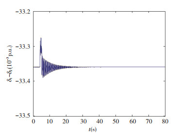
|
Figure 1 The power angle response curve of generator |
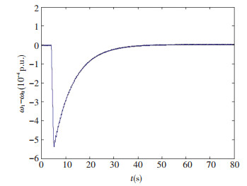
|
Figure 2 The rotor angular velocity response curve of the first generator |
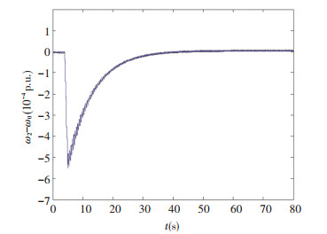
|
Figure 3 The rotor angular velocity response curve of the second generator |
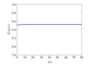
|
Figure 4 The q-axis transient potential response curve of the first generator |
|
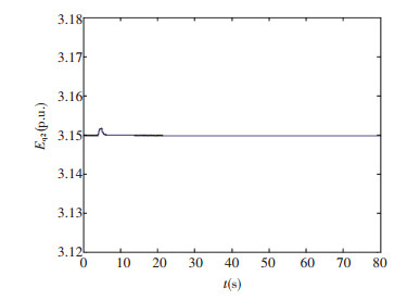
Figure 5 The q-axis transient potential response curve of the second generator |
The goal of power system transient stability control is to make each generator tend to the rated synchronous speed[22]. As can be seen from the simulation results shown in Figs. 1-5, after a period of adjustment, the system can reach a stable operating point again. The difference of angular speed and synchronous speed of generator converges to zero, and the rotor running angle of each generator converges to a fixed angle, and the stability is good. The system has a strong robustness to external disturbance, and the ideal control effect is obtained.
In order to test the control effect, the controller designed in this paper is compared with the controller based on DIEB (Damping Injection Energy Balancing) in Ref.[19].
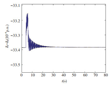
Comparing Fig. 1 and Fig. 6, it can be seen that the turbulence amplitude in the paper is less than that in Ref.[19], and the response time is also less than that in Ref.[19]. The controller designed in the paper is better than that in Ref.[19].
|
Figure 6 The power angle response curve by the method in Ref.[19] |
To verify the adaptive ability of power system, the parameter variations of power system are considered. Let
| $ {{T'}_{d01}} = 8.96\;{\rm{p}}.{\rm{u}}.\;,{{T'}_{d02}} = 6.32\;{\rm{p}}.{\rm{u}}. $ |
| $ \mathit{\boldsymbol{B}} = \left[ {{\mathit{\boldsymbol{B}}_{ij}}} \right] = \left[ {\begin{array}{*{20}{c}} { - 2.8522}&{1.5130}\\ {1.5130}&{ - 2.9138} \end{array}} \right] $ |
Assuming that the sudden three phase short circuit fault takes place at 4 s again, x′d2=0, and is resected after 1.2 s, the simulations are shown in Figs. 7-11.

|
Figure 7 The power angle response curve of generator |

|
Figure 8 The rotor angular velocity response curve of the first generator |

|
Figure 9 The rotor angular velocity response curve of the second generator |
|
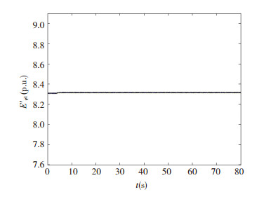
Figure 10 The q-axis transient potential response curve of the first generator |

|
Figure 11 The q-axis transient potential response curve of the second generator |
As can be seen from Figs. 6-10, the controller has a strong adaptive ability to the parameter perturbation of system. When the system parameters have changed, the system tends to be stable, and the good control effect is obtained.
5 ConclusionsIn this paper, the adaptive H∞ control scheme of multi-machine power system with control time delay and parameter uncertainty is studied based on Hamiltonian function. Considered the time delay effect in the transmission process of control, a Hamilton model with control delay is established. Selected the appropriate Lyapunov-Krasovskii function, an adaptive robust H∞ state feedback control law is derived which can guarantee the asymptotic stability of the system. H∞ controller can realize the disturbance suppression, and adaptive control can improve the robustness of system to uncertain parameters. The simulation results show that the designed controller makes the power system to be stable, and the effect of the proposed controller is tested.
| [1] |
Xu L M, Wang Y, Cao J L. Robust controller design for switched two-machine power system. Journal of Southwest University for Nationalities(Natural Science Edition), 2014, 40(1): 115-119. DOI:10.3969/j.issn.1003-4271.2014.01.23 (  0) 0) |
| [2] |
Wang J, Cheng C. Structure Preserving Power System- Bifurcation and Stability Control. Beijing: Science Press, 2009.
(  0) 0) |
| [3] |
Tang Y. Wide area security and stability control of power system based on response. Chinese Journal of Electrical Engineering, 2014, 34(29): 41-50. DOI:10.13334/j.0258-8013.pcsee.2014.29.005 (  0) 0) |
| [4] |
Mazhari S M, Kouhsari S M, Ramirez A. A novel frequency-domain approach for distributed harmonic analysis of multi-area interconnected power systems. Electric Power Systems Research, 2016, 143: 669-681. DOI:10.1016/j.epsr.2016.10.048 (  0) 0) |
| [5] |
Paszek S, Nocoń A. Parameter polyoptimization of PSS2A power system stabilizers operating in a multi-machine power system including the uncertainty of model parameters. Applied Mathematics and Computation, 2015, 267: 750-757. DOI:10.1016/j.amc.2014.12.013 (  0) 0) |
| [6] |
Demirdelen T, Kayaalp R I, Tumay M. Simulation mo-delling and analysis of modular cascaded multilevel converter based shunt hybrid active power filter for large scale photovoltaic system interconnection. Simulation Modelling Practice and Theory, 2017, 71: 27-44. DOI:10.1016/j.simpat.2016.11.003 (  0) 0) |
| [7] |
Islam N N, Hannan M A, Shareef H, et al. An application of backtracking search algorithm in designing power system stabilizers for large multi-machine system. Neurocomputing, 2016, 237: 175-184. DOI:10.1016/j.neucom.2016.10.022 (  0) 0) |
| [8] |
Tang K, Venayagamoorthy G K. Adaptive inter-area os-cillation damping controller for multi-machine power systems. Electric Power Systems Research, 2016, 134: 105-113. DOI:10.1016/j.epsr.2016.01.005 (  0) 0) |
| [9] |
Farah A, Guesmi T, Abdallah H H, et al. A novel chaotic teaching-learning-based optimization algorithm for multi-machine power system stabilizers design problem. International Journal of Electrical Power & Energy Systems, 2016, 77: 197-209. DOI:10.1016/j.ijepes.2015.11.050 (  0) 0) |
| [10] |
Fombu A M, Kenné G, de Dieu Nguimfack-Ndongmo J, et al. Decentralized nonlinear coordinated excitation and steam valve adaptive control for multi-machine power systems. International Journal of Electrical Power & Energy Systems, 2016, 75: 117-126. DOI:10.1016/j.ijepes.2015.08.021 (  0) 0) |
| [11] |
Furtat I B, Fradkov A L. Robust control of multi-machine power systems with compensation of disturbances. International Journal of Electrical Power & Energy Systems, 2015, 73: 584-590. DOI:10.1016/j.ijepes.2015.05.042 (  0) 0) |
| [12] |
Meng J. Research on Nonlinear Robust Control of Ship Power System. Harbin: Harbin Engineering University, 2011.
(  0) 0) |
| [13] |
Shen T, Mei S, Lu Q, et al. Adaptive nonlinear excitation control with L2 disturbance attenuation for power systems. Automatica, 2003, 39(1): 81-89. DOI:10.1016/S0005-1098(02)00175-9 (  0) 0) |
| [14] |
Liu Q J, Sun Y Z, Shen T L, et al. Adaptive nonlinear coordinated excitation and STATCOM controller based on Hamiltonian structure for multimachine-power-system stability enhancement. Control Theory and Applications, IEE Proceedings, 2003, 150(3): 285-294. DOI:10.1049/ip-cta:20030319 (  0) 0) |
| [15] |
Wang F, Liu Q H. Simulationresearch of intelligent power system stabilizer based on fuzzy control. East China Electric Power, 2011, 39(7): 1120-1122. (  0) 0) |
| [16] |
Sun Y, Li Z M, Zhang D S, et al. Power system stabilizer based on fuzzy neural network with improved learning algorithm. Electric Power Automation Equipment, 2009, 29(6): 58-61. (  0) 0) |
| [17] |
Dubey M. Design of genetic algorithm based fuzzy logic power system stabilizers in multimachine power system. Wseas International Conference on Systems. World Scientific and Engineering Academy and Society (WSEAS), 2009, 39-46. (  0) 0) |
| [18] |
Dubey M. Design of genetic algorithm basedfuzzy logic power system stabilizers in multimachine power system. Joint International Conference on Power System Technology and IEEE Power India Conference, 2008. Piscataway: IEEE, 2008, 1-6. (  0) 0) |
| [19] |
Shi F, Wang J, Xue G T. Coordinated excitation and SVC control based on Hamilton theory for improving transient stability of multi machine system. Electric Power Automation Equipment, 2012, 32(10): 48-52. (  0) 0) |
| [20] |
Sun Y, Peng J. A newLyapunov function for transient stability analysis of power system with emergency control. International Conference on Power System Technology, 2002. Proceedings. PowerCon 2002. Piscataway:IEEE, 2002, 3: 1540-1544. DOI:10.1109/ICPST.2002.1067791 (  0) 0) |
| [21] |
Gulizhati H T L, Wang J. Wide-area time-delay damping control of generalized Hamilton multi-machine power system. Chinese Journal of Electrical Engineering, 2014, 34(34): 6199-6208. DOI:10.13334/j.0258-8013.pcsee.2014.34.023 (  0) 0) |
| [22] |
Wu Z Q, Yao Y, Dou C X. Fuzzy adaptive control for multi-machine power system. Power System Protection and Control, 2011, 39(10): 5-10. (  0) 0) |
 2018, Vol. 25


