2. School of Mathematics, Sun Yat-sen University, Zhuhai 519082, Guangdong, China;
3. National Engineering Research Centre for Advanced Polymer Processing Technology, Zhengzhou University, Zhengzhou 450002, China
Ultra-thin injection molding refers to a product whose nominal thickness is at most 0.5 mm or flow length to thickness ratio is greater than 100. In the injection molding process, in order to overcome the high flow resistance and force the melt filling the cavity smoothly, high injection speed is required to form the product, which has a significant impact on the shear stress distribution of the melt flow field[1-2].The most important influence lies in the orientation in the part[3]. Compared with the skin-core structure of the traditional injection molding, the microstructure of the ultra-thin injection molding presents a clear orientation structure from the surface to the core in the thickness direction of the part due to its small wall thickness and large flow shear stress, which increases the anisotropy in mechanical properties[4-5], especially for nano-composites molding. CNT-filled polymer composites have been developed rapidly and applied extensively in recent years due to their excellent electrical properties and mechanical properties[5-6].For CNT-filled polymer injection molding, the highly oriented conductive filler CNT gives the product good electrical conductivity along the flow direction, whereas in the thickness direction the material seepage threshold becomes larger due to the discontinuous conductive network. This is one of the important factors that affect the electrical conductivity of CNT-filled polymer. In order to improve its conductivity, the molding is often treated by isothermal annealing in the practical application. During the isothermal annealing process, the conductive filler, CNT, is gradually changed from a highly oriented state to a uniformly distributed state, so that the conductive anisotropy is gradually restored to isotropic[7-8].
It is well known that high orientation is one of the thermodynamically unstable structures of polymer material which has the characteristics of spontaneous relaxation and recovery into a stable curl structure. The relaxation and the recovery may be accelerated by increasing temperature. For the ultra-thin injection of CNT-filled polymer conductive composites, these questions, such as the recovery dynamics of its high orientation structure, the change of electrical conductivity, and the stability of the conductivity in service, are essential for its industrial application[9]. In order to further study the problem, we applied different compression strains to the molding by a hot-rolling process. The mechanism of relaxation and recovery of highly oriented microstructure was investigated according to the change of orientation degree during rolling.
The relationship between the formation of microstructure and the processing parameters of rolling deformation on polymer has attracted the interest of many researchers. Qiu and Murata[10] studied the change of crystallinity and the distribution of crystal orientation of PP in the process of rolling deformation. Tomita and Uchida[11] proposed several deformation mechanisms for different crystallinity of PP, including phase-separation, interlayer shear and interlayer slip.Uchida and Tada[12] studied the phase transformation behavior of PP during tensile deformation. These studies found that the crystalline structure of PP could disappear in the process of deformations, which was confirmed to be related with the interlayer shear caused by the deflection of the direction of the crystal chip relative to the deformation direction. In addition, the influences of other process conditions, such as deformation temperature, strain level, on the deformation behavior of other semi-crystalline materials have also been studied by Schrauwen et al.[13] extensively.
In the studies mentioned above, the original microstructure of the molding was uniform before the rolling deformation. In this paper, ultra-thin injection molded CNT-filled PP samples were subjected to different thermal rolling compressive deformations. The main purposes were to clarify the relaxation and the recovery mechanism of the molding with strong orientation microstructure, to evaluate the effect of the recovery on the stability of molding's conductivity[14]. We used SEM and two-dimensional wide-angle X-ray diffraction (2D-WAXD) to observe the orientation of the response process. An alternating bending device was used to test the stability of the conductivity of the sample under the dynamic loading.
2 Experiments 2.1 Materials and SamplesCommercial PP (T30S) with a melt flow index of 2.6 g/10 min (190 ℃, 21.6 N) was provided by Lanzhou Petroleum Chemical Co., China. PP was filled with TNIM4CNT (Chengdu Organic Chemistry Corp., China) which the density is 2.1 g/cm3 , 95% carbon purity, 9.5 nm in diameter and 15 μm in length. PP-CNT master batch was prepared using a two-step compounding process to disperse CNT in the PP matrix uniformly. First, a compound with 20 wt% CNT was fabricated using a SHJ-35 twin-screw extruder with a screw length ratio of 40 L/D. The temperature was 200 ℃and a rotation speed of twin screw was 200 r/min and a through put was 20 kg/h. Second, the master batch was diluted to 3 wt% CNT by compounding with PP to get PP-3 wt% CNT. PP-3 wt% CNT pellet was feed into injection molding machine (An 80-ton Demag Plastic Group) to fabricate ultra-thin molding. The mold contained a rectangular cavity with a fan gate. The size of the mold's cavity in length, width, thickness was 100 mm, 10 mm and 0.5 mm, respectively. The temperature profile on the barrel was 200 ℃, 220 ℃, 220 ℃, 200 ℃ and 190 ℃ from the hopper to the nozzle head. The injection speed was 600 mm/s, the cooling time 20 s and the mold temperature 50 ℃.
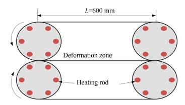
2.2 Hot-rolling ProcessA molding was reheated to temperature 155 ℃ and compressed by a modified hot-rolling device, as shown in Fig. 1. Rolling heating time was set to 90 s. The thickness of the molding after rolling was 0.4 mm and 0.2 mm, and the corresponding thermal compressive strain was 20% and 60%, respectively. The sample was marked as S20 and S60 respectively.
|
Figure 1 Schematic diagram of the hot-rolling device |
In order to explore the reconstruction mechanism of the oriented microstructure under the loading strain, the molding was reheated to the same temperature in a vacuum oven for 90 s, then cooled rapidly in water to keep the heated microstructure. This sample was marked as A90.
2.3 Microstructure ObservationThe sample was dipped into liquid nitrogen, fractured and etched by a solution mixture of 1:1 volume of concentrated sulfuric acid and nitric acid by dissolving 0.7 wt % of potassium permanganate to examine the microstructure of the cross-section. The etched surface was sputter-coated with a layer of gold.SEM was done with an accelerating voltage of 20 kV.2D-WAXD was performed at the beam line BL16B1 of Shanghai Synchrotron Radiation Facility (SSRF). 2D-WAXD data were collected for each point on the library at ambient temperature using Cu-Ka radiation for 180 s. The background of all the 2D-WAXD patterns given in this article had been extracted and thus allowed a qualitative comparison between various samples. CNT angle distribution θ was manually determined by image for 100 CNTs for a unit element. Here, θ is the angle of CNT relative to the flowing direction. Since many CNTs had kinked and showed some waviness, a CNT end-to-end distance vector was defined and used as a reference for the angle determination throughout. To evaluate the orientation degree of CNT, the Herman's orientation function f was calculated:
| $ f = \frac{{3\left\langle {{{\cos }^2}\varphi } \right\rangle-1}}{2} $ | (1) |
where φ is the angle between the chain axis of a CNT and the rolling direction, and 〈cos2φ〉 is definedas:
| $ \left\langle {{{\cos }^2}\varphi } \right\rangle = \frac{{\int_0^{\frac{\pi }{2}} {I\left( \varphi \right){{\cos }^2}\varphi \sin \varphi {\text{d}}\varphi } }}{{\int_0^{\frac{\pi }{2}} {I\left( \varphi \right)\sin \varphi {\text{d}}\varphi } }} $ | (2) |
where I(φ) is the intensity. Because there is no pure reflection from c-axis of PP, 〈cos2φ〉 is calculated by using Wilchinsky's method[15] from the (110) and (040) reflections:
| $ \left\langle {{{\cos }^2}\varphi } \right\rangle = 1-1.090\left\langle {{{\cos }^2}{\varphi _{110}}} \right\rangle-0.901\left\langle {{{\cos }^2}{\varphi _{040}}} \right\rangle $ | (3) |
The orientation function f=1 when all CNTs are oriented with their c-axis parallel to the rolling direction, f=-0.5 when CNTs are oriented with their c-axis perpendicular to the rolling direction, and f=0 for a random orientation[16].
2.4 Measurement of the Conductivity and Mechanical PropertyThe volume resistivity of the part was measured by the DC resistor across the thickness of the sample. For each sample, the I-V curve was obtained and the resistivity of the sample was determined from the slope of the curve. The resistivity was then converted to volume resistivity, ρv, using the formula:
| $ {\rho _\nu } = A{R_v}/D $ | (4) |
where A is the contact surface area, D is the thickness of the sample, and Rv is the measured resistance. Prior to measurements all samples were dried in the vacuum heating oven. In order to eliminate the influence of the background current, an alternating polarity resistance test method was adopted.
The tensile properties of the sample were tested by Instron 1011 universal tensile tester at a crosshead speed of 1 mm/min according to ASTM 638-03. Alternative loading tests were conducted at room temperature on a servo-hydraulic test machine (MTS Model 20Kip). Dog-bone shaped samples were prepared and their edges were sanded to reduce the possibility of edge-related failures. Aluminum tabs were bonded to the ends of the samples using a two-component epoxy to grip. The samples were tested under load-control mode, and the stress ratio R, between the minimum stress and the maximum stress, was set to 0.1. The shape of the loading waveform was sinusoidal and the employed frequency was 3 Hz to avoid sample heating. The number of cycles to failure (N) was recorded for each sample. At least three samples were tested for each condition to ensure the reliability of the data.
3 Results and Discussions 3.1 Recovery of Oriented MicrostructuresIn order to investigate the influence of thermal compressive strain on the recovery of the highly oriented microstructure, the molding was compressed by means of the rolling device shown in Fig. 1 under the temperature 155 ℃, and its microstructure was observed[17]. The results are shown in Fig. 2.
|
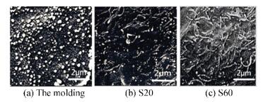
Figure 2 The effect of different thermal compressive strains on the redistribution of oriented CNT |
Fig. 2(a) is a microstructure of the cross-section perpendicular to the flow direction. The uniform distribution of CNT with circular cross-sections can be clearly observed from Fig. 2(a), indicating that CNT are aligned along the flow direction due to high injection rate and large flow shear stress. Fig. 2(b) shows the microstructure of the cross-section of the sample with a transverse hot compressing strain of 20%. Compared with Fig. 2(a), the orientation of CNT is clearly changed, which indicates that the highly oriented polymer molecular chains are partially relaxed under the compression strain, and the orientation of CNT is induced to be deflected by the polymer relaxation. Fig. 2(c) shows the microstructure of the cross-section of the sample with a transverse hot compressing strain of 60%. Compared with Fig. 2(a) and 2(b), the degree of orientation of CNT is further reduced, which is much closer to random distribution, indicating that the polymer chains are further relaxed[18-19]. In order to confirm the inference, we calculated the orientation degree of CNT on the basis of measuring the orientation angle, and analyzed the orientation of the polymer chains by 2D-WAXD[20]. The results are shown in Fig. 3 and Fig. 4.
|
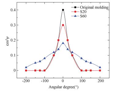
Figure 3 CNT oriented distribution determined by digital image analysis |
|
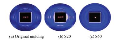
Figure 4 Scattering patterns of 2D-WAXS of the samples |
Fig. 3 shows that the angular deviation of CNT from the flowing direction spanned the range [-50°, +50°] for original molding. With the increase of thermal compressive strain, the angular deviation was obviously widen to [-180°, +180°]. The distributions were characterized by the Herman's function which yielded the values f: 0.97±0.08, 0.78±0.07, 0.31±0.09 and 0.25±0.09 respectively[21].
Fig. 4 shows the representative 2D-WAXD patterns of the molding experienced different thermal compressive strains. For S60, the diffraction patterns show diffuse scattering without any crystal reflection. In contrast, sharp reflection arcs are clearly observed in the samples of the original molding and S20. It should be noted that the appearance of arclike or pointlike diffraction pattern indicates the presence of highly oriented crystal, whereas crystal without preferred orientation exhibits circular ring pattern[22].
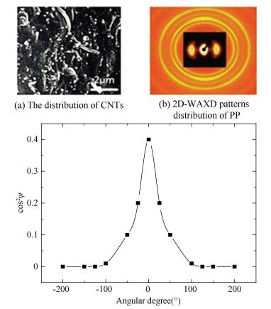
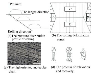
In order to clarify the mechanism of the effect of hot compressing strain on orientation recovery, we annealed the sample with high orientation structure under the same heating temperature and heating time as the hot rolling. The results are shown in Fig. 5. It can be seen from Fig. 5(a) and Fig. 5(b) that the distribution of CNTs and PP polymer chains still maintains some injection molding orientation structure after annealing. The result of the orientation in Fig. 5(c) is consistent with the result of the microstructure. The results show that an additional stress field has the effect of accelerating the relaxation of the nano-filled polymer composites with high orientation back to the equilibrium state. The recovery process and its mechanism can be explained by Fig. 6.
|
Figure 5 The orientation of the samples |
|
Figure 6 The deformation and recovery illustration of the samples during heated rolling |
Fig. 6(a) and 6(b) show the pressure distribution profile of the sample shown in Fig. 1. It can be seen that the pressure at both ends of the rollers is smaller than its center position along the longitudinal direction of the rolling, which makes the deformation resistance of each area of the sample non-uniform in the process of rolling deformation. The rolling deformation of the sample is divided into four zones in the press roll. A and B regions are elongated regions, and C and D are spread regions, as shown in Fig. 6(b). When the compressive strain is larger than a certain value, the deformation resistance in the length direction is greater than the deformation resistance in the width direction. Under this condition, the polymer composite is mainly spread and not elongated. In the process of spread deformation, the highly oriented molecular chain, as shown in Fig. 6(c), relaxes under the action of the external loading field and the temperature field. Meanwhile, polymer chains slide in the direction of spread, which accelerates the recovery of the highly oriented molecular chain to the curled equilibrium state, as shown in Fig. 6(d).
At the same time, CNTs are deflected in different directions under the movement of polymer chains, and finally form a random distribution state. In the process of CNT orientation recovery induced by hot compression deformation, the macromolecules play dual functions: CNTs are pinned by polymer chains to ensure that CNTs are continuous with the matrix, and on the other hand CNTs are in traction of the macromolecular chain.
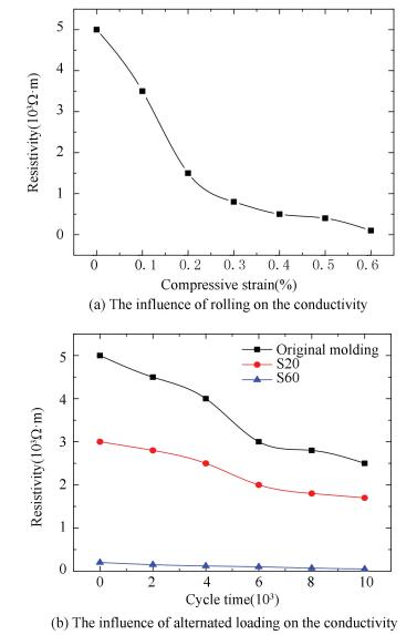
3.2 The Effect of Thermal Compressive Strain on the ConductivityCNT distribution in the matrix is going to be uniform with the increase of thermal compressive strains, which improves the conductivity of the samples. The measurements of the resulting conductivity are shown in Fig. 7(a). In order to explore the thermal dynamic behavior of the samples after hot rolling, the sample of original molding, S20 and S60 was reheated to temperature 120 ℃ respectively under the action of alternated bending load [23]. The change of the conductivity on the samples was recorded and shown in Fig. 7(b).
|
Figure 7 The influence of rolling and alternated loading on the conductivity |
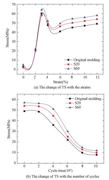
Fig. 7(b) indicates that CNT-filled PP nano-composites that experienced thermal compressive strains present better conductive stability during alternated loading. The results were inspected to be related with the hardening effect of the polymer chains during rolling deformation process. Tensile strength test was carried out to clarify this speculation. The results of tensile strength test are showed in Fig. 8(a). The stress-strain curves depicted in Fig. 8(a) illustrate that the level of compressive strain has a significant influence on tensile deformation behavior. In order to quantitatively estimate tensile properties, the average values of ultimate tensile strength were determined from the stress-strain curves and summarized in Fig. 8(a).
|
Figure 8 The mechanical property of the samples |
As seen in Fig. 8(a), the S60 exhibits maximum tensile strength (TS). Based on the comprehensive analysis of aforementioned microstructure, the increasing strength of S60 likely depends on forming β-crystal morphology of PP[24-25]. From the monotonic stress-strain curves in Fig. 8(a), it can be clearly observed that all the samples exhibit a yield softening point at strain 3% or so, which represents the onset of permanent deformation. After yield deformation, the samples present a region of cold drawing at almost constant stress. Obviously, the strengthening effect from cold drawing of S60 is larger than the other samples. Close to the fracture, strain strengthening phenomenon can be observed in the samples after hot compressive strain. It indicates that CNT-filled PP ultra-thin molding follows Hooke's law before yield point and exhibit high resistance to cold drawing deformation, which is believed to be related to the cracked crystal plate in the amorphous phase during the compressive stain[26].
It is easily seen in Fig. 8(b) that the tensile strength decreases with increasing cycles of alternated loading until the alternated loading cycles is larger than a critical value. This appearance indicates that a stable molecular arrangement is formed in the amorphous phase. The compressive strains of a semi-crystalline polymer material can be viewed as deformation of two interpenetrated networks built up by interlocked lamellae (the crystalline phase) and entangled amorphous phase. The macromolecular chains which exist in both crystalline and amorphous regions will form a bridge chain, acting as physical cross-link, connecting crystal and amorphous regions[27]. During the compressive deformation, the bridge chains gradually change their orientation to the direction of deformation and form a mesophase between crystal and amorphous regions.
4 ConclusionsCompared with the annealing treatment process on ultra-thin injection molding, the hot-rolling can accelerate the relaxation and recovery of high-orientation structure of CNT-filled PP molding.This effect is mainly from the two aspects: the relaxation of polymer macromolecule chains and the transverse deformation induced by hot compression.The recovery of CNT orientations and the macromolecule chains can be sped up through raising thermal compression strain. If the compressive strain is greater than a certain value, the transverse spread deformation of the sample is larger than its elongation in the rolling direction because the deformation resistance in the rolling direction is stronger than one in the spread direction. The slide in intramacromolecule chains result in the transverse deformation which is helpful to the formation of the balanced entanglement structure. Under the dual action of "pinning" and "traction" of the macromolecule chains, the distribution of CNT is changed from high orientation to randomness. The reduction of orientation degree makes CNT form continuous three-dimensional conductive network in PP matrix, which improves the conductivity of the material. The deformation strengthening of PP during the rolling improves the stabilities of the mechanical property and the conductivity of ultra-thin injection molded CNT-filled PP composites under the action of alternating loads.
| [1] |
Huang Han-Xiong, Zhou Run-Heng, Yang Can. Fiber orientation propelled by high-pressure water penetration in water-assisted injection molded fiber-reinforced thermoplastics part. Journal of Composite Materials, 2013, 47(2): 183-190. DOI:10.1177/0021998312438083 (  0) 0) |
| [2] |
Shokri P, Bhatnagar N. Effect of packing pressure on fiber orientation in injection molding of fiber-reinforced thermoplastics. Polymer Composites, 2007, 28(2): 214-223. DOI:10.1002/pc.20234 (  0) 0) |
| [3] |
Villmow T, Pegel S, Pötschke P. Influence of injection molding parameters on the electrical resistivity of polycarbonate filled with multi-walled carbon nanotubes. Composites Science & Technology, 2008, 68(3-4): 777-789. DOI:10.1016/j.compscitech.2007.08.031 (  0) 0) |
| [4] |
Hong C M, Kim J, Jana S C. Shear-induced migration of conductive fillers in injection molding. Polymer Engineering & Science, 2004, 44(11): 2101-2109. DOI:10.1002/pen.20215 (  0) 0) |
| [5] |
Battisti A, Skordos A A, Partridge I K. Percolation threshold of carbon nanotubes filled unsaturated polyesters. Composites Science & Technology, 2010, 70(4): 633-637. DOI:10.1016/j.compscitech.2009.12.017 (  0) 0) |
| [6] |
Yu Feilong, Deng Hua, Zhang Qin, et al. Anisotropic multilayer conductive networks in carbon nanotubes filled polyethylene/polypropylene blends obtained through high speed thin wall injection molding. Polymer, 2013, 54(23): 6425-6436. DOI:10.1016/j.polymer.2013.09.047 (  0) 0) |
| [7] |
Villmow T, Pegel S, Pötschke P, et al. Influence of injection molding parameters on the electrical resistivity of polycarbonate filled with multi-walled carbon nanotubes. Composites Science & Technology, 2008, 68(3-4): 777-789. DOI:10.1016/j.compscitech.2007.08.031 (  0) 0) |
| [8] |
Bhuiyan M A, Pucha R V, Worthy J, et al. Defining the lower and upper limit of the effective modulus of CNT/polypropylene composites through integration of modeling and experiments. Composite Structures, 2013, 95(1): 80-87. DOI:10.1016/j.compstruct.2012.06.025 (  0) 0) |
| [9] |
Coclite A M, Gleacon K. Controlling the degree of crystallinity and preferred crystallographic orientation in poly-perfluorodecylacrylate thin films by initiated chemical vapor deposition. Advanced Functional Material, 2012, 22(10): 2167-2176. DOI:10.1002/adfm.201103035 (  0) 0) |
| [10] |
Qiu J H, Murata T, Wu X L, et al. Plastic deformation mechanism of crystalline polymer materials during the rolling process. Journal of Materials Science, 2013, 48(5): 1920-1931. DOI:10.1007/s10853-012-6957-2 (  0) 0) |
| [11] |
Tomita Y, Uchida M. Computational characterization of micro-to mesoscopic deformation behavior of semicrystalline polymers. International Journal of Mechanical Sciences, 2005, 47(4-5): 687-700. DOI:10.1016/j.ijmecsci.2004.10.011 (  0) 0) |
| [12] |
Uchida M, Tada N. Micro-, meso-to macroscopic modeling of deformation behavior of semi-crystalline polymer. International Journal of Plasticity, 2013, 49(9): 164-184. DOI:10.1016/j.ijplas.2013.03.007 (  0) 0) |
| [13] |
Schrauwen B A G, Janssen R P M. Intrinsic deformation behavior of semicrystalline polymers. Macromolecules, 2004, 37(16): 6069-6078. DOI:10.1021/ma035279t (  0) 0) |
| [14] |
Hu Tingting, Dai Kun, Zheng Guoqiang. Progress in liquid sensing behaviour of conductive polymer composites. Shanghai Plastics, 2012, 40(40): 126-139. (  0) 0) |
| [15] |
Wilchinsky Z W. Orientation in cold-rolled polypropylene. Journal of Applied Polymer Science, 2010, 7(3): 923-933. DOI:10.1002/app.1963.070070311 (  0) 0) |
| [16] |
Duan Y, Saigal A, Greif R. A uniform phenomenological constitutive model for glassy and semicrystalline polymers. Polymer Engineering & Science, 2001, 41(8): 1322-1328. DOI:10.1002/pen.10832 (  0) 0) |
| [17] |
Jia J, Raabe D. Evolution of crystallinity and of crystallographic orientation in isotactic polypropylene during rolling and heat treatment. European Polymer Journal, 2006, 42(8): 1755-1766. DOI:10.1016/j.eurpolymj.2006.02.013 (  0) 0) |
| [18] |
Puchi-Cabrera E S. Simple constitutive description of Al-5·5Mg alloy deformed at elevated temperatures and strain rates. Materials Science and Technology, 2006, 22(6): 699-705. DOI:10.1179/174328406X86137 (  0) 0) |
| [19] |
Bartczak Z, Beris P F M, Wasilewski K, et al. Deformation of the ultra-high molecular weight polyethylene melt in the plane-strain compression. Journal of Applied Polymer Science, 2012, 125(6): 4155-4168. DOI:10.1002/app.36595 (  0) 0) |
| [20] |
Bartczak Z. Effect of chain entanglements on plastic deformation behavior of ultra-high molecular weight polyethylene. Journal of Polymer Science (Part B) Polymer Physics, 2010, 48(3): 276-285. DOI:10.1002/pold.21873 (  0) 0) |
| [21] |
Kibria M A, Anisur M R, Mahfuz M H, et al. A review on thermophysical properties of nanoparticle dispersed phase change materials. Energy Conversion & Management, 2015, 95(5): 69-89. DOI:10.1016/j.enconman.2015.02.028 (  0) 0) |
| [22] |
Suljovrujic E. The influence of molecular orientation on the crosslinking/oxidative behaviour of iPP exposed to gamma radiation. European Polymer Journal, 2009, 45(7): 2068-2078. DOI:10.1016/j.eurpolymj.2009.03.017 (  0) 0) |
| [23] |
Burton A W, Ong K, Rea T, et al. On the estimation of average crystallite size of zeolites from the Scherrer equation: A critical evaluation of its application to zeolites with one-dimensional pore systems. Microporous & Mesoporous Materials, 2009, 117(1-2): 75-90. DOI:10.1016/j.micromeso.2008.06.010 (  0) 0) |
| [24] |
Liu Zhongzhu, Li Guangsen, Fu Yanqin, et al. Influence of annealing temperature on microstructures and mechanical properties of β-nucleated isotactic polypropylene films. Modern Plastics Processing and Application, 2015, 27(4): 10-12. (  0) 0) |
| [25] |
Liu Zhongzhou, Zheng Haili, Zheng Guoqiang, et al. Effect of β nucleating agent on the microstructure and mechanical properties of iPP films. Modern Plastics Processing and Application, 2013, 25(5): 35-37. (  0) 0) |
| [26] |
Sekihara M, Ichikawa K, Imano S. Refurbishment of creep damage using Re-heat process for Ni-based superalloy under bending load. Journal of the Society of Materials Science Japan, 2011, 60(3): 202-209. DOI:10.2472/jsms.60.202 (  0) 0) |
| [27] |
Guseva M A, Gerasin V A, Garishin O K, et al. Thermal effects under elastic and plastic deformation of polyethylene. Polymer, 2015, 56(4): 416-427. DOI:10.1016/j.polymer.2014.11.041 (  0) 0) |
 2018, Vol. 25


