2. Department of Aerodynamics, Nanjing University of Aeronautics and Astronautics, Nanjing 210016, China
With the rapid growth of simulation scale, there exists an urgent demand for higher computational efficiency. According to the Moore's law, the performance of computer chips will double every two years until the physical size of microprocessor reaches tens of nanometer. At present, the most advanced microprocessor is reaching this limit, and the improvement of the chip's performance is slowing down. As a result, traditional multi-core CPUs computers can no longer satisfy researchers′ requests for large computing capability. Therefore, heterogeneous architectures, which combine traditional multi-core CPUs with highly efficient accelerators[1], come into service. Among these accelerators, the graphics processing unit (GPU) has gained great attention because of its remarkable computing power. For example, the NVIDIA Tesla K80 GPU accelerator is capable of processing nearly 3000 G floating-point operations per second, so it is an order of magnitude higher compared with the contemporaneous Intel CPU processor.
During the past two decades, the lattice Boltzmann method (LBM)[2] has evolved into a promising model to simulate various fluid dynamic problems. Considering its algorithmic simplicity, easy boundary treatment and intrinsic nature of parallel computation, LBM can be a high-efficiency tool in fluid simulation. Thus, there exists a great potential to explore in massively parallel programming of LBM by using GPU.
However, the architecture of GPU is a far cry from CPU, which means programmers must be familiar with the hardware architectures before starting the parallel programming. At present, CUDA (Compute Unified Device Architecture) from NVIDIA is widely used to transform the serial code into a parallel one. That's quite a challenge for most researchers. Extra time will be consumed to master a GPU programming language and much more time is needed to rewrite the serial code thoroughly, not to mention the various platforms with uncertain prospect on the market. Whilst, OpenACC (OpenACCelerator)[3] is a platform independent, high level, and directive based programming standard. After adding some OpenACC directives as annotations, the compilers are capable of understanding the programmer's intentions, and then locate and offload the computationally intensive region to the GPU accelerator. Automatically, it will take full advantage of accelerator's extraordinary compute capability. By using the OpenACC directives, users can implement the parallel computation easily. In addition, they also can freely compile the same code and conduct computations on either CPU or GPU from different vendors. To the best of our knowledge, there already exists some research in utilizing the GPU accelerators in parallelizing the LBM simulation codes[4-5], but very few implementations of LBM together with OpenACC acceleration can be found in Refs. [6-9]. On the other hand, some previous studies have shown the great potential of OpenACC in the field of fluid simulation[10-14]. It motivates us to continue to apply OpenACC to the acceleration of LB simulations.
This paper is structured as follows: Section 2 introduces the numerical methods used briefly. Section 3 describes OpenACC programming model and our efforts in OpenACC implementation and optimization. Section 4 analyzes the benchmark performance results, and all the work is summarized in Section 5.
2 Numerical Methods 2.1 Lattice Boltzmann MethodTo simulate the two-dimensional viscous and incompressible flow by using LBM, the following equation is solved, which can be written as[2]
| $ \begin{array}{*{20}{c}} {{f_\alpha }\left( {\mathit{\boldsymbol{x}} + {\mathit{\boldsymbol{e}}_\alpha }\delta t,t + \delta t} \right) - {f_\alpha }\left( {\mathit{\boldsymbol{x}},t} \right) = }\\ { - \frac{1}{\mathit{\boldsymbol{\tau }}}\left[ {{f_\alpha }\left( {\mathit{\boldsymbol{x}},t} \right) - f_\alpha ^{eq}\left( {\mathit{\boldsymbol{x}},t} \right)} \right]} \end{array} $ | (1) |
In Eq.(1), the right hand side means the collision sub-process, and the left hand side represents the stream sub-process. In addition, fα is the density distribution function, fαeq is the equilibrium status, τ is the single relaxation time, δt is the time step, and eα is the lattice velocity. In this paper, the D2Q9 lattice model is used and its lattice velocity set is
| $ {\mathit{\boldsymbol{e}}_\alpha } = \left\{ {\begin{array}{*{20}{c}} \begin{array}{l} \left( {0,0} \right),\\ \left( { \pm 1,0} \right),\left( {0, \pm 1} \right),\\ \left( { \pm 1, \pm 1} \right), \end{array}&\begin{array}{l} \alpha = 0\\ \alpha = 1 - 4\\ \alpha = 5 - 8 \end{array} \end{array}} \right. $ | (2) |
and then the equilibrium distribution function is
| $ \begin{array}{l} f_\alpha ^{eq}\left( {\mathit{\boldsymbol{x}},t} \right) = \\ \;\;\;\;\;\rho {w_\alpha }\left[ {1 + \frac{{{\mathit{\boldsymbol{e}}_\alpha } \cdot \mathit{\boldsymbol{u}}}}{{c_s^2}} + \frac{{{{\left( {{\mathit{\boldsymbol{e}}_\alpha } \cdot u} \right)}^2} - {{\left( {{c_s}\left| \mathit{\boldsymbol{u}} \right|} \right)}^2}}}{{2c_s^4}}} \right] \end{array} $ | (3) |
where ρ is flow density, u is the flow velocity vector, and cs2=1/3. wα is the coefficient, w0=4/9, w1~4=1/9 and w5~8=1/36. The relationship between the relaxation time and the kinematic viscosity of fluid is υ=(τ-0.5)cs2δt.
2.2 Immersed Boundary MethodWhen the object is introduced into the flow field, the immersed boundary method (IBM) can be used to deal with the boundary of object. In the framework of LBM, therefore, the resultant governing equations of immersed boundary-lattice Boltzmann method (IB-LBM) can be written as[15]
| $ \begin{array}{*{20}{c}} {{f_\alpha }\left( {\mathit{\boldsymbol{x}} + {\mathit{\boldsymbol{e}}_\alpha }\delta t,t + \delta t} \right) - {f_\alpha }\left( {\mathit{\boldsymbol{x}},t} \right) = }\\ { - \frac{1}{\mathit{\boldsymbol{\tau }}}\left[ {{f_\alpha }\left( {\mathit{\boldsymbol{x}},t} \right) - f_\alpha ^{eq}\left( {\mathit{\boldsymbol{x}},t} \right)} \right] + {F_\alpha }\delta t} \end{array} $ | (4) |
| $ {F_\alpha } = \left( {1 - \frac{1}{{2\tau }}} \right){\mathit{\boldsymbol{w}}_\alpha }\left( {\frac{{{\mathit{\boldsymbol{e}}_\alpha } - \mathit{\boldsymbol{u}}}}{{c_s^2}} + \frac{{{\mathit{\boldsymbol{e}}_\alpha } \cdot \mathit{\boldsymbol{u}}}}{{c_s^4}}{\mathit{\boldsymbol{e}}_\alpha }} \right) \cdot f $ | (5) |
| $ \rho \mathit{\boldsymbol{u}} = \sum\limits_\alpha {{\mathit{\boldsymbol{e}}_\alpha }{f_\alpha }} + \frac{1}{2}\mathit{\boldsymbol{f}}\delta t $ | (6) |
where Fα describes the effect of immersed boundary, f is the force density in flow field, which can be distributed from the boundary force density.
To guarantee the no-slip boundary condition, the force density f in Eqs. (5) and (6) can firstly be set as unknown. Then the force density f can be transformed to the fluid velocity correction δu, which is determined by the boundary velocity correction δuB. So the equation system related to δuB can be written as
| $ \mathit{\boldsymbol{AX}} = \mathit{\boldsymbol{B}} $ | (7) |
where
| $ X = {\left\{ {\delta \mathit{\boldsymbol{u}}_B^1,\delta \mathit{\boldsymbol{u}}_B^2, \cdots ,\delta \mathit{\boldsymbol{u}}_B^m} \right\}^{\rm{T}}} $ |
| $ \mathit{\boldsymbol{A}} = \left( {\begin{array}{*{20}{c}} {{\delta _{11}}}&{{\delta _{12}}}& \cdots &{{\delta _{1n}}}\\ {{\delta _{21}}}&{{\delta _{22}}}& \cdots &{{\delta _{2n}}}\\ \vdots&\vdots&\ddots&\vdots \\ {{\delta _{m1}}}&{{\delta _{m2}}}& \cdots &{{\delta _{mn}}} \end{array}} \right)\left( {\begin{array}{*{20}{c}} {\delta _{11}^B}&{\delta _{12}^B}& \cdots &{\delta _{1m}^B}\\ {\delta _{21}^B}&{\delta _{22}^B}& \cdots &{\delta _{2m}^B}\\ \vdots&\vdots&\ddots&\vdots \\ {\delta _{n1}^B}&{\delta _{n2}^B}& \cdots &{\delta _{nm}^B} \end{array}} \right) $ |
| $ \mathit{\boldsymbol{B}} = \left( {\begin{array}{*{20}{c}} {\mathit{\boldsymbol{U}}_B^1}\\ {\mathit{\boldsymbol{U}}_B^2}\\ \vdots \\ {\mathit{\boldsymbol{U}}_B^m} \end{array}} \right) - \left( {\begin{array}{*{20}{c}} {{\delta _{11}}}&{{\delta _{12}}}& \cdots &{{\delta _{1n}}}\\ {{\delta _{21}}}&{{\delta _{22}}}& \cdots &{{\delta _{2n}}}\\ \vdots&\vdots&\ddots&\vdots \\ {{\delta _{m1}}}&{{\delta _{m2}}}& \cdots &{{\delta _{mn}}} \end{array}} \right)\left( {\begin{array}{*{20}{c}} {\mathit{\boldsymbol{u}}_1^ * }\\ {\mathit{\boldsymbol{u}}_2^ * }\\ \vdots \\ {\mathit{\boldsymbol{u}}_n^ * } \end{array}} \right) $ |
Here, m is the number of boundary points, n is the number of surrounding Eulerian mesh points, δuBl (l=1, 2, …, m) is the unknown boundary velocity correction vector, δij and δijB are the delta functions, which are used to connect the flow field and the boundary. For more details of the IB-LBM used here, one can refer to our previous work[15].
3 OpenACC TechniqueThe only purpose of parallelization is to make the best use of existing hardware resources thus accelerating the program. This is also a direction where the OpenACC programming model works. In OpenACC, two tasks must be done for parallelization, one is parallelizing the computation and the other is data management. To accomplish these two jobs, OpenACC uses different directives as annotations, compute constructs like kernels or parallel for parallelizing, and data clauses like data/end data or enter/exit data for data management. During the parallel execution, all the data needed is transferred from CPU host to the accelerator device, and the calculation job is offloaded to the GPU.
To assess the performance and efficiency of OpenACC programming precisely, all the attempts in this work are conducted in one computer with Windows 10 (Enterprise Edition) system, which is equipped with an Intel i7-7700K CPU, a Gloway DDR4 RAM with 16GB and a NVIDIA GeForce GTX 1070 GPU accelerator with 8GB under the compiler platform of PGI 17.10 community edition. All the simulations below are performed by using one CPU core.
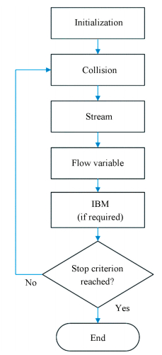
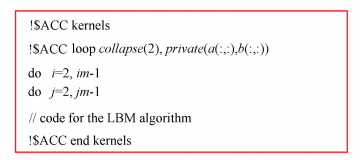
The OpenACC implementation of LB simulations code consists of several steps. The first one is to locate the computationally intensive regions of code. After assessing the numerical algorithm, it's easy to find the hotspot in code which is computationally intensive and contains potential in parallelization. Fig. 1 shows the flow chart of LB simulations. There are several subroutines in the code: collision, stream, flow variable, and IBM if required. Due to the intrinsic parallel nature of LBM, these subroutines are specifically suitable for parallel computation. Then, the second step is to add OpenACC kernels/parallel loop directives to offload the most computationally intense loops to the GPU accelerator, as shown in Fig. 2. At this stage, all the distribution function and flow variable arrays are copied form CPU host to GPU and transferred back to CPU host for each time step. This may result in a significant loss of performance owing to redundant data movement.
|
Figure 1 Flow chart of LB simulations |
|
Figure 2 Use of ACC directives in LB simulations |
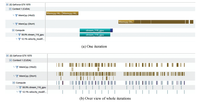
Fig. 3 plots the data movement profiling through NVIDIA Visual Profiler. As a tiny test, the iteration steps are set as 200. As can be seen from the figure, the data movement occurs every time the accelerator launches a parallel kernel. It costs 15.853 s to finish the computation. Comparing with the serial version of LB code (16.318 s), it shows no speedup in efficiency. Nonetheless, the computation task has been offloaded to the GPU and the result obtained is correct. In the next step, it will improve dramatically.
|
Figure 3 Data movement profiling without data clause |
Therefore, the next step is to decrease the meaningless data movement between the host and accelerator. During the iteration, all the data is calculated in GPU accelerator. If they are temporarily stored in the GPU, data exchange can be removed to overcome the high cost of data transfer and kernel launch. After initializing the parameters and flow field, all the arrays needed can be copied to the GPU storage space without exchange until the end of the iteration. To realize this, as shown in Fig. 4, a data region is established by data clauses, which includes "copy", "copyin", "copyout" and "create". All the arrays can obtain allocated memory in GPU by different data clauses depending on their data characteristics (such as global variable, intermediate variable, etc).

|
Figure 4 Use of data region for time iteration |
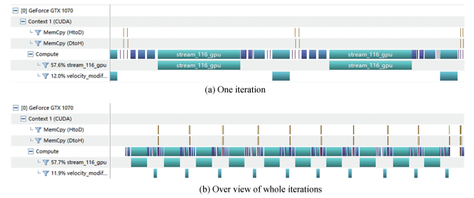
As illustrated in Fig. 4, in this sample code for flow over a stationary circular cylinder, some arrays are declared in the "acc data" clause. Once the flow field initialization is accomplished, the "copyin" clause is used since the mesh and cylinder information is constant, and then updating the data to CPU host is junk effort. These data remain in the device memory and will not be sent back after the end of iteration. There are also some variables acting as intermediate variables and only work in a particular subroutine. They do not need initial values from the CPU host, nor does the host needs theirs. The "create" clause fits them well. Last but not least, the data exchange of flow variables (such as velocity, density) between host and device are necessary, and so "copy" clause works. After adding the data clause, as shown in Fig. 5, the time for data movement is reduced significantly. It costs only 1.525 s to finish the 200 iterations, which is a speed increase of over 10 times. With precise data management, heavy data transfer burden is relieved, which can lead to an improvement in performance.
|
Figure 5 Data movement profiling with data clause |
4 Numerical Examples
In this section, three fluid dynamic problems, i.e., lid-driven cavity flow, flows over a stationary circular cylinder, and an elastically mounted cylinder, are simulated to evaluate the performance of parallel LB codes ported by OpenACC. To show the efficiency and performance of parallel computation, the metrics of million lattice updates per second (MLUPS) is introduced, which is defined as[8]
| $ MLUPS = \frac{{\left( {mesh\;size} \right) \times \left( {iteration\;steps} \right)}}{{\left( {running\;time} \right) \times {{10}^6}}} $ | (8) |
With a given mesh size, the iteration steps are also fixed. Then, the running time can be measured. Less running time consumed, which produces higher MLUPS, means better parallel performance.
4.1 Lid-Driven Cavity FlowTo validate the LBM parallel code with OpenACC, the lid-driven cavity flow at different Reynolds numbers is simulated. For this problem, the Reynolds number is defined as Re=UL/υ. In which, U is the driving velocity of lid, and L is the length of cavity. Three left walls are stationary. The computational domain is discretized by using the uniform mesh. Four Reynolds numbers are considered, i.e., Re=1 000, 5 000, 7 500 and 10 000. Correspondingly, the mesh sizes are 241×241, 361×361, 521×521 and 841×841.
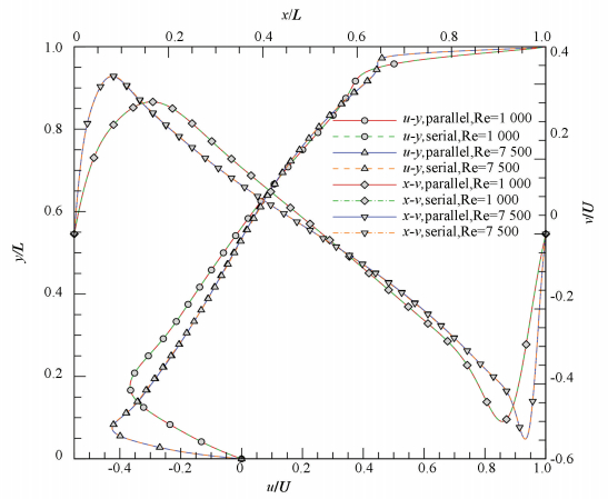
To verify the results obtained by the parallelized LBM code, Fig. 6 presents the velocity profiles along the centerlines of the cavity at Re=1 000 and 7 500. The results computed by using LBM serial code, which have been widely validated[2], are involved to make comparison. It can be found from the figure that both results compare very well with each other. Fig. 7 shows the streamlines of parallel simulations at different Reynolds numbers, in which the clear development of vortex structures is demonstrated[2].
|
Figure 6 Comparison of centerline velocity profiles at Re=1 000 and 7 500 |

|
Figure 7 Streamlines of lid-driven cavity flow at Re=1 000, 5 000, 7500 and 10 000 |
Table 1 summarizes the performance between serial computation and parallel computation at four different mesh sizes and Reynolds numbers. From the table, one can find an interesting tendency. With the increase of mesh size, the speedup also grows. It means that although the parallel efficiency is directly relevant to the capability of accelerator device, the performance of parallelism also can be improved with the boost of computation scale. However, there is a physical limit. When the computation scale increases up to a certain degree, enlarging the scale solely can no longer bring an increased acceleration profit.
| Table 1 Performance comparison of serial and parallel computations for lid-driven cavity flow |
4.2 Flow Over a Stationary Circular Cylinder
To also validate the IB-LBM parallel code with OpenACC, the flow over a stationary circular cylinder is simulated. The Reynolds number for this problem is defined as Re=UD/υ, where U is the free stream velocity and D is the diameter of the cylinder. The free stream condition is applied to four boundaries. The computational domain is discretized by using the non-uniform mesh, in which the mesh is fine and uniform around the cylinder. Two different Reynolds numbers are considered, i.e., Re=40 and 200, which represent steady and unsteady states, respectively. For both states, the mesh size is fixed at 461×421.
Similar to the lid-driven cavity flow problem above, the IB-LBM serial code has also been run. For the case of Re=40, the drag coefficient and recirculation region behind the cylinder from parallel simulation are 1.563 and 4.63, respectively. They are the same as the results of serial simulation. For the case of Re=200, the same time histories of drag and lift coefficients can be observed from the comparison in Fig. 8. In addition, the streamlines and instantaneous vorticity contours from parallel simulations, which are plotted in Fig. 9, also compare very well with that of our previous study[15].

|
Figure 8 Comparison of time history of drag and lift coefficients at Re=200 |

|
Figure 9 Streamlines and instantaneous vorticity contours of flow over a stationary circular cylinder at Re=40 and 200 |
Table 2 provides the performance of serial and parallel computations at different Reynolds numbers. As can be found from the table, the implementation of parallel acceleration for the problem of flow over a stationary circular cylinder gets a speedup about 22×. Compared with the case of lid-driven cavity flow with the similar mesh size, there is a bit of performance loss. It is partially owing to the introduction of an immersed boundary method, which brings in extra complexity in algorithm and parallel implementation. Nevertheless, the improvement of performance comparing with the serial one is still satisfactory.
| Table 2 Performance comparison of serial and parallel computations for flow over a stationary circular cylinder |
4.3 Flow Over an Elastically Mounted Cylinder
After simulating the flow over a stationary circular cylinder, the current IB-LBM parallel code is further used to simulate the flow over an elastically mounted cylinder. Since the cylinder is elastically mounted, it may experience vibration under some specific conditions, which is called as vortex-induced vibration (VIV).
For an elastically mounted cylinder having one degree of freedom, its motion can be described by the following equation[16]:
| $ \ddot Y + {\left( {\frac{{2{\rm{ \mathsf{ π} }}}}{{{U^ * }}}} \right)^2}Y = \frac{{{C_l}}}{{2{m^ * }}} $ | (9) |
where Y=y/D and y is the displacement of the cylinder, U* is the reduced velocity of the cylinder that is related to the response of the cylinder to fluid flow, Cl is the lift coefficient acting on the cylinder, m* is the mass ratio of the cylinder to the fluid. In the current simulation, U*=5 and m*=2 are used, which can produce the obvious periodic VIV of cylinder. Moreover, the Reynolds number is fixed at Re=200. Same as the stationary cylinder problem, the mesh size is also chosen as 461×421.
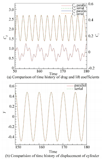
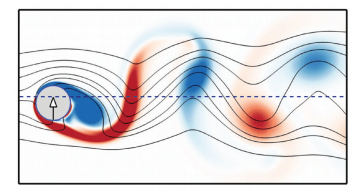
Fig. 10 plots the time histories of drag and lift coefficients and the displacement of cylinder from serial and parallel computations. Again, perfect agreement can be achieved. The maximum displacement is 0.478, which is close to that of Borazjani and Sotiropoulos (0.467)[16]. Fig. 11 presents the streamlines and instantaneous vorticity contours. At this moment, the cylinder is moving upward. Compared with the case of stationary cylinder, it can be found that the streamlines and vorticity contours show clear difference.
|
Figure 10 Comparison of time history of drag and lift coefficients and displacement of cylinder at Re=200 |
|
Figure 11 Streamlines and instantaneous vorticity contours of flow over an elastically mounted cylinder at Re=200 |
Since the cylinder can oscillate along y direction, the position data of cylinder needs to be updated each iteration step. It brings extra complexity for parallelization and burden for data management. But still the performance gets improved about 11 times faster than the serial implementation.
5 ConclusionsIn this work, the acceleration of the lattice Boltzmann simulation has been implemented by using the GPU parallel technique. Different from the CUDA programming language, OpenACC is a high level directive based programming standard. During the code parallelization process, OpenACC directives are very effective. After introducing precise data transfer arrangements, the use of OpenACC can receive a reasonable speedup of over 30 times for the LB simulations. Three typical fluid dynamic problems, i.e., lid-driven cavity flow, flows over a stationary circular cylinder and an elastically mounted cylinder, are simulated to validate the parallel codes. Compared with the serial codes, a dramatic improvement in performance can be achieved. The extension to use the advanced features of OpenACC and the interoperability with platform (like cuBLAS) will be implemented in future work.
| [1] |
Foster I. Designing and Building Parallel Programs: Concepts and Tools for Parallel Software Engineering. New Jersey: Addison-Wesley, 1995.
(  0) 0) |
| [2] |
Aidun C K, Clausen J R. Lattice-Boltzmann method for complex flows. Annual Review of Fluid Mechanics, 2010, 42(1): 439-472. DOI:10.1146/annurev-fluid-121108-145519 (  0) 0) |
| [3] |
Chandrasekaran S, Juckeland G. OpenACC for Programmers: Concepts and Strategies. New Jersey: Addison-Wesley, 2018.
(  0) 0) |
| [4] |
Riesinger C, Bakhtiari A, Schreiber M, et al. A holistic scalable implementation approach of the lattice Boltzmann method for CPU/GPU heterogeneous clusters. Computation, 2017, 5(4): 48. DOI:10.3390/computation5040048 (  0) 0) |
| [5] |
Calore E, Gabbana A, Schifano S F, et al. Optimization of lattice Boltzmann simulations on heterogeneous computers. The International Journal of High Performance Computing Applications, 2018. Online First. DOI: 10.1177/1094342017703771.
(  0) 0) |
| [6] |
Calore E, Kraus J, Schifano S F, et al. Accelerating lattice Boltzmann applications with OpenACC. In: Traff J, Hunold S, Versaci F.(eds) European Conference on Parallel Processing, Lecture Notes in Computer Science, 2015, 9233: 613-624. DOI: 10.1007/978-3-662-48096-0_47.
(  0) 0) |
| [7] |
Calore E, Gabbana A, Kraus J, et al. Performance and portability of accelerated lattice Boltzmann applications with OpenACC. Concurrency and Computation: Practice and Experience, 2016, 28(12): 3485-3502. DOI:10.1002/cpe.3862 (  0) 0) |
| [8] |
Xu A, Shi L, Zhao T S. Accelerated lattice Boltzmann simulation using GPU and OpenACC with data management. International Journal of Heat and Mass Transfer, 2017, 109: 577-588. DOI:10.1016/j.ijheatmasstransfer.2017.02.032 (  0) 0) |
| [9] |
Xu A, Shyy W, Zhao T S. Lattice Boltzmann modeling of transport phenomena in fuel cells and flow batteries. Acta Mechanica Sinica, 2017, 33(3): 555-574. DOI:10.1007/s10409-017-0667-6 (  0) 0) |
| [10] |
Couder-Castañeda C, Barrios-Piña H, Gitler I, et al. Performance of a code migration for the simulation of supersonic ejector flow to SMP, MIC, and GPU using OpenMP, OpenMP+LEO, and OpenACC directives. Scientific Programming, 2015. Article ID 739107. DOI: 10.1155/2015/739107.
(  0) 0) |
| [11] |
Rostami R M, Ghaffari-Miab M. Fast computation of finite difference generated time-domain Green's functions of layered media using OpenACC on graphics processors. 2017 Iranian Conference on Electrical Engineering, Piscataway: IEEE, 2017. 1596-1599. DOI: 10.1109/IranianCEE.2017.7985300.
(  0) 0) |
| [12] |
Zhang S H, Yuan R, Wu Y, et al. Implementation and efficiency analysis of parallel computation using OpenACC: A case study using flow field simulations. International Journal of Computational Fluid Dynamics, 2016, 30(1): 79-88. DOI:10.1080/10618562.2016.1164309 (  0) 0) |
| [13] |
Xia Y, Lou J, Luo H, et al. OpenACC acceleration of an unstructured CFD solver based on a reconstructed discontinuous Galerkin method for compressible flows. International Journal for Numerical Methods in Fluids, 2015, 78(3): 123-139. DOI:10.1002/fld.4009 (  0) 0) |
| [14] |
Ma W, Lu Z, Yuan W, et al. Parallelization of an unsteady ALE solver with deforming mesh using OpenACC. Scientific Programming, 2017. Article ID 4610138. DOI: 10.1155/2017/4610138.
(  0) 0) |
| [15] |
Wu J, Shu C. Implicit velocity correction-based immersed boundary-lattice Boltzmann method and its applications. Journal of Computational Physics, 2009, 228(6): 1963-1979. DOI:10.1016/j.jcp.2008.11.019 (  0) 0) |
| [16] |
Borazjani I, Sotiropoulos F. Vortex-induced vibrations of two cylinders in tandem arrangement in the proximity-wake interference region. Journal of Fluid Mechanics, 2009, 621: 321-364. DOI:10.1017/S0022112008004850 (  0) 0) |
 2018, Vol. 25


