Since 1980's, there are many ways of developments in the study of electromagnetic launching technique, with increasingly wider application fields especially in military tactics, which can be used to develop high technology weapon. For example: used in space-based anti-missile system, air defense system, anti-armor weapon system, equipped with artillery, equipped naval ships[1-2], etc. Electromagnetic energy will gradually replace chemical energy to be the major energy of weapon launching[3], driving and destroying, such as laser weapon, directed energy weapon, dynamic energy weapon and so on. These weapons are all based on the physics of electromagnetic energy high efficiency transformation and releasing high energy transiently, and have incredible application prospects.
The first wholly successful 9MJ range railing gun was manufactured by American in 1992, and was tested in land force Yuma test center[4].
US navy held a test at Naval Surface Warfare Ctr., Dahlgren Div. Detachment at the morning of 31st, Jan. 2008, using a kind of electromagnetic launcher which was known as the biggest in the world to accelerate 3 kg aluminum shell to 2.5 km/s, and the launching energy reached 10.06 MJ. On 10th, Dec. 2010, US navy succeeded another electromagnetic launcher sample. Its shell speed was over 5 times sound velocity and the range was up to 110 miles (204 km) as well as the generated electric energy up to 33 MJ, which was 3 times of the test in Jan. 2008[5]. On 28th, Feb. 2012, US navy tested the first electromagnetic launcher made by military enterprise at Dahlgren on-ground combat center. The shell speed was up to 7 000-8 000 km/h, the attacking range was 90-180 km, and the longest distance could be 400 km. It is expected to deliver guns to the Navy in April[6].
These years, emerging electromagnetic launching techniques broke through the inherent limitations and disadvantages of traditional launching which satisfied the requirement of high launching speed to a certain extent[7] and developed a new approach of launching technique. There are many problems to be resolved in the procedure of designing electromagnetic launcher[8-10]. Concerning rectangular launcher, the rigidity of launching rails and panels must be ensured in order to ensure launching accuracy. However, the relative study is still seldom.
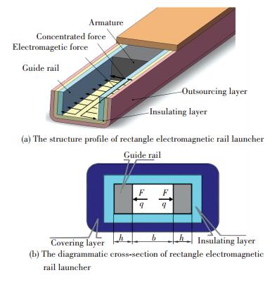
The sketch of rectangular electromagnetic launcher is shown in Fig. 1. The insulation layer between rails and panels can be looked as elastic foundation, and the panels are fixed by bolts with the cover board. The deformation of cover board and bolts under work conditions can be looked as another elastic foundation. Therefore, under launching procedure, thstress and strain of rails and panels should be calculated. When launching, current is coming into rails, armature is forced by strong thrust, from calculating the repulsion q between the rails and the armature expansion under joule heat, the force on the rails can be obtained by armature F[11-12]. Therefore, the launching rail can be simplified as bi-layer elastic foundation beam under the action of electromagnetic force q and armature force F.
|
Figure 1 Diagram of rectangle electromagnetic rail launcher |
The electromagnetic rail launching theory and application have been studied more than one hundred years, but till now most studies are still detained in examination. The technique of electromagnetic rail launching develops slowly because of some problems in engineering technology and manufacture process[13]. Among the problems, the theoretical analysis of strength, rigidity and thermal stress on rails, armature, working tube, filling stuff, outer shell and so on as well as the coupling effect analysis of force field, electromagnetic field and temperature field[14-16], are the major problems to be resolved sooner.
Presently, the study of electromagnetic launcher is mostly concentrated in three fields of electromagnetic analysis, mechanical analysis and new materials. In the field of mechanical analysis, most studies focus on strength, rigidity and dynamic response of the launcher component[11]. But it has to be pointed that the launcher is too heavy and big, one of the reasons is that the calculating study of component strength and rigidity is still plain and far away from the request of application. In thesis of Tzeng[17], classic theory of material mechanics is used to calculate the strength and deformation of launcher shell under stepped loads. In the thesis of Johnson and Moon[18], the rail of electromagnetic launcher is simplified as elastic foundation beam, calculating by material mechanics method, the stress wave's transmission characteristic of the rail under electromagnetic force is preliminary analyzed. However, the physical truth is different from that the rail is only simplified to monolayer elastic foundation beam.
Bi-layer elastic foundation beam is common in the field of aeronautics and astronautics, civil engineering, road engineering and marine engineering. It is pointed out in Ref.[19] that the design and calculation of rocket's sled rails are mostly used by the mechanical mode of bi-layer elastic foundation beam. However, it was always simplified as monolayer, infinite or half infinite elastic foundation beam. This is obviously not suitable to the actual working conditions. The analytical solution of finite bi-layer elastic foundation beam also can be used in such fields mentioned above with the value of generalization[20].
In this thesis, the rails and panels of rectangular electromagnetic launcher under electromagnetic force and armature force are simplified as bi-layer elastic foundation beam under distribution load and concentrated load.The insulation between the rails and panels is equivalent to a layer of elasticity. The panels are usually connected by bolts and covers. The deformation of covers and bolts in the working state can be equivalent to another layer of elasticity for the panels. From basic equations of elasticity and generalized Krylov Function, the analytical solution of the strain and stress of rails and panels can be obtained. The analysis of rigidity and strength of rails and panels can support design consideration to reduce the volume and weight of the launcher as well as improve its strength, rigidity and service life.
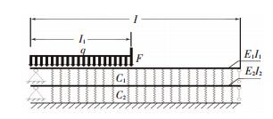
2 Establishment of Differential Equation of Bi-Layer Elastic Foundation Beam 2.1 Establishment of Mechanical Model of Bi-Layer Elastic Foundation BeamThe launcher's rails and panels are simplified as bi-layer beams system on Winkler elastic foundation, as shown in Fig. 2. According to Bernouli-Euler beam theory, presetting the upper and lower part of the beams to be hinged, and their bending rigidity are E1I1, E2I2; c1 is the elastic constant of the elastic foundation between upper and lower beam; c2 is the elastic constant between lower beam and elastic foundation; if the loads are confirmed, the deformation of upper and lower beams are depended on E1I1, E2I2, c1 and c2. Set foundation pressure of the upper beam as p1=c1(w1-w2), and p2=c2w2 for lower beam.
|
Figure 2 Mechanical model of bi-layer beam |
2.2 Establishment of Deflection Curve Equation of Bi-layer Elastic Foundation
The two beams' static balance differential equation can be listed concerning above[21].
As to the upper beam,
| $ {E_1}{I_1}\frac{{{{\rm{d}}^4}{w_1}}}{{{\rm{d}}x_1^4}} = - {p_1} = - {c_1}\left( {{w_1} - {w_2}} \right) $ | (1) |
As to the lower beam,
| $ {E_2}{I_2}\frac{{{{\rm{d}}^4}{w_2}}}{{{\rm{d}}x_2^4}} = - \left( {{p_2} - {p_1}} \right) = - \left( {{c_1} + {c_2}} \right){w_2} + {c_1}{w_1} $ | (2) |
By Eq.(1),
| $ {w_2} = \frac{{{E_1}{I_1}}}{{{c_1}}}\frac{{{{\rm{d}}^4}{w_1}}}{{{\rm{d}}x_1^4}} + {w_1} $ | (3) |
As the length of upper and lower beam is equal, set x1=x2, then
| $ \frac{{{{\rm{d}}^4}{w_2}}}{{{\rm{d}}{x^4}}} = \frac{{{E_1}{I_1}}}{{{c_1}}}\frac{{{{\rm{d}}^8}{w_1}}}{{{\rm{d}}{x^8}}} + \frac{{{{\rm{d}}^4}{w_1}}}{{{\rm{d}}{x^4}}} $ |
Insert it to Eq.(2), then
| $ \begin{array}{l} {E_2}{I_2}\frac{{{E_1}{I_1}}}{{{c_1}}}\frac{{{{\rm{d}}^8}{w_1}}}{{{\rm{d}}{x^8}}} = {E_2}{I_2}\frac{{{{\rm{d}}^4}{w_1}}}{{{\rm{d}}{x^4}}} = - \left( {{c_2} + {c_1}} \right) \cdot \\ \;\;\;\;\;\;\left( {\frac{{{E_1}{I_1}}}{{{c_1}}}\frac{{{{\rm{d}}^4}{w_1}}}{{{\rm{d}}{x^4}}} + {w_1}} \right) + {c_1}{w_1} \end{array} $ |
After sorting,
| $ \frac{{{{\rm{d}}^8}{w_1}}}{{{\rm{d}}{x^8}}} + 2\alpha \frac{{{{\rm{d}}^4}{w_1}}}{{{\rm{d}}{x^4}}} + \left( {\alpha - \beta } \right){w_1} = 0 $ | (4) |
where
| $ \alpha = \frac{{{c_1}\left( {{E_1}{I_1} + {E_2}{I_2}} \right) + {c_2}{E_1}{I_1}}}{{2{E_1}{I_1}{E_2}{I_2}}} $ |
| $ \beta = \frac{{\left( {{c_1} + {c_2}} \right){E_1}{I_1} + {c_1}{E_2}{I_2} - 2{c_1}{c_2}}}{{2{E_1}{I_1}{E_2}{I_2}}} $ |
Then the general solution of Eq.(4) is:
| $ \begin{array}{l} {w_1}\left( x \right) = {{\rm{e}}^{{k_1}x}}\left[ {{C_1}\cos \left( {{k_1}x} \right) + {C_2}\sin \left( {{k_1}x} \right)} \right] + \\ \;\;\;{{\rm{e}}^{ - {k_1}x}}\left[ {{C_3}\cos \left( {{k_1}x} \right) + {C_4}\sin \left( {{k_1}x} \right)} \right] + \\ \;\;\;{{\rm{e}}^{{k_2}x}}\left[ {{C_5}\cos \left( {{k_1}x} \right) + {C_6}\sin \left( {{k_1}x} \right)} \right] + \\ \;\;\;{{\rm{e}}^{ - {k_2}x}}\left[ {{C_7}\cos \left( {{k_1}x} \right) + {C_8}\sin \left( {{k_1}x} \right)} \right] \end{array} $ | (5) |
where Ci(i=1, 2, …, 8) is undetermined coefficient, and
| $ {k_1} = {\mathop{\rm Re}\nolimits} \left[ {\frac{{{{\left( { - \alpha - \sqrt {{\alpha ^2} - \alpha + \beta } } \right)}^{\frac{1}{4}}}}}{{1 + {\rm{J}}}}} \right] $ |
| $ \begin{array}{*{20}{c}} {{k_2} = {\mathop{\rm Re}\nolimits} \left[ {\frac{{{{\left( { - \alpha + \sqrt {{\alpha ^2} - \alpha + \beta } } \right)}^{\frac{1}{4}}}}}{{1 + {\rm{J}}}}} \right]}\\ {{\rm{J}} = \sqrt { - 1} } \end{array} $ |
Insert Eq.(5) to Eq. (2), then
| $ \begin{array}{l} {w_2}\left( x \right) = \left( {1 - \frac{{4{E_1}{I_1}k_1^4}}{{{c_1}}}} \right)\left\{ {{{\rm{e}}^{{k_1}x}}\left[ {{C_1}\cos \left( {{k_1}x} \right) + } \right.} \right.\\ \;\;\;\;\left. {{C_2}\sin \left( {{k_1}x} \right)} \right] + {{\rm{e}}^{ - {k_1}x}}\left[ {{C_3}\cos \left( {{k_1}x} \right) + } \right.\\ \left. {\;\;\;\;\left. {{C_4}\sin \left( {{k_1}x} \right)} \right]} \right\} + \left( {1 - \frac{{4{E_1}{I_1}k_2^4}}{{{c_1}}}} \right)\left\{ {{{\rm{e}}^{{k_2}x}}\left[ {{C_5}\cos \left( {{k_2}x} \right) + } \right.} \right.\\ \left. {\;\;\;\;\left. {{C_6}\sin \left( {{k_2}x} \right)} \right] + {{\rm{e}}^{ - {k_2}x}}\left[ {{C_7}\cos \left( {{k_2}x} \right) + {C_8}\sin \left( {{k_2}x} \right)} \right]} \right\} \end{array} $ | (6) |
It is easily concluded from Eqs.(1) to (4): all equations are without load on the beams, and Eqs. (5) and (6) are the general solutions of the homogenous equation. As the loads are unconfirmed, usually it is hard to get the analytical solution with specific value.
2.3 Establishment of Generalized Krylov FunctionIn order to get the analytical solution of bi-layer elastic foundation beams under ensured load, w1(x) and w2(x) are written as follows:
| $ \begin{array}{l} {w_1}\left( x \right) = {f_1} \cdot {w_1}\left( 0 \right) + {f_2} \cdot {{w'}_1}\left( 0 \right) + {f_3} \cdot {{w''}_1}\left( 0 \right) + \\ \;\;\;\;\;\;\;\;\;\;\;\;{f_4} \cdot {{w'''}_1}\left( 0 \right) + {f_5} \cdot {w_2}\left( 0 \right) + {f_6} \cdot {{w'}_2}\left( 0 \right) + \\ \;\;\;\;\;\;\;\;\;\;\;\;{f_7} \cdot {{w''}_2}\left( 0 \right) + {f_8} \cdot {{w'''}_2}\left( 0 \right) \end{array} $ | (7) |
| $ \begin{array}{l} {w_2}\left( x \right) = {f_9} \cdot {w_1}\left( 0 \right) + {f_{10}} \cdot {{w'}_1}\left( 0 \right) + {f_{11}} \cdot {{w''}_1}\left( 0 \right) + \\ \;\;\;\;\;\;\;\;\;\;\;\;{f_{12}} \cdot {{w'''}_1}\left( 0 \right) + {f_{13}} \cdot {w_2}\left( 0 \right) + {f_{14}} \cdot {{w'}_2}\left( 0 \right) + \\ \;\;\;\;\;\;\;\;\;\;\;\;{f_{15}} \cdot {{w''}_2}\left( 0 \right) + {f_{16}} \cdot {{w'''}_2}\left( 0 \right) \end{array} $ | (8) |
Where
| $ {w_1}\left( 0 \right) = {w_1}\left| {_{x = 0}} \right.,{{w'}_1}\left( 0 \right) = \frac{{{\rm{d}}{w_1}}}{{{\rm{d}}x}}\left| {_{x = 0}} \right. $ |
| $ {{w''}_1}\left( 0 \right) = \frac{{{{\rm{d}}^2}{w_1}}}{{{\rm{d}}{x^2}}}\left| {_{x = 0}} \right.,{{w'''}_1}\left( 0 \right) = \frac{{{{\rm{d}}^3}{w_1}}}{{{\rm{d}}{x^3}}}\left| {_{x = 0}} \right. $ |
| $ {w_2}\left( 0 \right) = {w_2}\left| {_{x = 0}} \right.,{{w'}_2}\left( 0 \right) = \frac{{{\rm{d}}{w_2}}}{{{\rm{d}}x}}\left| {_{x = 0}} \right. $ |
| $ {{w''}_2}\left( 0 \right) = \frac{{{{\rm{d}}^2}{w_2}}}{{{\rm{d}}{x^2}}}\left| {_{x = 0}} \right.,{{w'''}_2}\left( 0 \right) = \frac{{{{\rm{d}}^3}{w_2}}}{{{\rm{d}}{x^3}}}\left| {_{x = 0}} \right. $ |
They are separately shown the initial value and derivative value of the upper and lower beams' left deflection. f1-f16 are undetermined function, which called "generalized krylov function". The method to confirm f1-f16 is listed as follows:
When: w1(0)=1, w1′(0)=1, w1″(0)=1, w1"′(0)=1, w2(0)=1, w2′(0)=1, w2″(0)=1, w2"′(0)=1, and the other 7 initial parameters are 0, then 8 equations can be obtained by Eqs.(5) and (6), which relative C1-C8 can be calculated, then put into Eq. (5), the follow expressions are obtained:
| $ \begin{array}{l} {f_1} = \frac{{\left( {{c_1} - 4{E_1}{I_1}k_2^4} \right)\left( {{{\rm{e}}^{{k_1}x}} + {{\rm{e}}^{ - {k_1}x}}} \right)}}{{8\left( {k_1^4 - k_2^4} \right){E_1}{I_1}}}\cos \left( {{k_1}x} \right) + \\ \;\;\;\;\;\;\;\frac{{\left( {{c_1} - 4{E_1}{I_1}k_1^4} \right)\left( {{{\rm{e}}^{{k_2}x}} + {{\rm{e}}^{ - {k_2}x}}} \right)}}{{8\left( {k_1^4 - k_2^4} \right){E_1}{I_1}}}\cos \left( {{k_2}x} \right) \end{array} $ | (9) |
| $ \begin{array}{l} {f_2} = \frac{{\left( {{c_1} - 4{E_1}{I_1}k_2^4} \right){k_2}}}{{16\left( {k_1^4 - k_2^4} \right){k_1}{k_2}{E_1}{I_1}}}\left[ {\left( {{{\rm{e}}^{{k_1}x}} - {{\rm{e}}^{ - {k_1}x}}} \right)\cos \left( {{k_1}x} \right) - } \right.\\ \;\;\;\;\;\;\;\left. {\left( {{{\rm{e}}^{ - {k_1}x}} + {{\rm{e}}^{{k_1}x}}} \right)\sin \left( {{k_1}x} \right)} \right] - \frac{{\left( {{c_1} - 4{E_1}{I_1}k_2^4} \right){k_1}}}{{16\left( {k_1^4 - k_2^4} \right){k_1}{k_2}{E_1}{I_1}}}\left[ {\left( {{{\rm{e}}^{{k_2}x}} - } \right.} \right.\\ \;\;\;\;\;\;\;\left. {\left. {{{\rm{e}}^{ - {k_2}x}}} \right)\cos \left( {{k_2}x} \right) - \left( {{{\rm{e}}^{ - {k_2}x}} + {{\rm{e}}^{{k_2}x}}} \right)\sin \left( {{k_2}x} \right)} \right] \end{array} $ | (10) |
| $ \begin{array}{l} {f_3} = \frac{{\left( {{c_1} - 4{E_1}{I_1}k_2^4} \right)k_2^2\left( {{{\rm{e}}^{{k_1}x}} + {{\rm{e}}^{ - {k_1}x}}} \right)}}{{16\left( {k_1^4 - k_2^4} \right)k_1^2k_2^2\left( {{E_1}{I_1}} \right)}}\sin \left( {{k_1}x} \right) - \\ \;\;\;\;\;\;\;\frac{{\left( {{c_1} - 4{E_1}{I_1}k_1^4} \right)k_1^2\left( {{{\rm{e}}^{{k_2}x}} - {{\rm{e}}^{ - {k_2}x}}} \right)}}{{16\left( {k_1^4 - k_2^4} \right)k_1^2k_2^2\left( {{E_1}{I_1}} \right)}}\sin \left( {{k_2}x} \right) \end{array} $ | (11) |
| $ \begin{array}{l} {f_4} = \frac{{\left( {{c_1} - 4{E_1}{I_1}k_2^4} \right)k_2^3}}{{32\left( {k_1^4 - k_2^4} \right)k_1^3k_2^3\left( {{E_1}{I_1}} \right)}}\left[ {\left( {{{\rm{e}}^{{k_1}x}} + } \right.} \right.\\ \;\;\;\;\;\;\;\left. {\left. {{{\rm{e}}^{ - {k_1}x}}} \right)\sin \left( {{k_1}x} \right) - \left( {{{\rm{e}}^{{k_1}x}} - {{\rm{e}}^{ - {k_1}x}}} \right)\cos \left( {{k_1}x} \right)} \right] - \\ \;\;\;\;\;\;\;\frac{{\left( {{c_1} - 4{E_1}{I_1}k_1^4} \right)k_1^3}}{{32\left( {k_1^4 - k_2^4} \right)k_1^3k_2^3\left( {{E_1}{I_1}} \right)}}\left[ {\left( {{{\rm{e}}^{{k_2}x}} + } \right.} \right.\\ \;\;\;\;\;\;\;\left. {\left. {{{\rm{e}}^{ - {k_2}x}}} \right)\sin \left( {{k_2}x} \right) - \left( {{{\rm{e}}^{{k_2}x}} - {{\rm{e}}^{ - {k_2}x}}} \right)\cos \left( {{k_2}x} \right)} \right] \end{array} $ | (12) |
| $ \begin{array}{l} {f_5} = \frac{{{c_1}}}{{8\left( {k_1^4 - k_2^4} \right){E_1}{I_1}}}\left[ {\left( {{{\rm{e}}^{{k_2}x}} + {{\rm{e}}^{ - {k_2}x}}} \right)\cos \left( {{k_2}x} \right) - } \right.\\ \;\;\;\;\;\;\left. {\left( {{{\rm{e}}^{{k_1}x}} + {{\rm{e}}^{ - {k_1}x}}} \right)\cos \left( {{k_1}x} \right)} \right] \end{array} $ | (13) |
| $ \begin{array}{l} {f_6} = \frac{{{c_1}}}{{16\left( {k_1^4 - k_2^4} \right){k_1}{k_2}{E_1}{I_1}}}\left[ {\left( {{{\rm{e}}^{{k_2}x}} + {{\rm{e}}^{ - {k_2}x}}} \right){k_1}\sin \left( {{k_2}x} \right) + } \right.\\ \;\;\;\;\;\;\;\left( {{{\rm{e}}^{{k_2}x}} - {{\rm{e}}^{ - {k_2}x}}} \right){k_1}\cos \left( {{k_2}x} \right) - \left( {{{\rm{e}}^{{k_1}x}} + {{\rm{e}}^{ - {k_1}x}}} \right){k_2}\sin \left( {{k_1}x} \right) - \\ \;\;\;\;\;\;\;\left. {\left( {{{\rm{e}}^{{k_1}x}} - {{\rm{e}}^{ - {k_1}x}}} \right){k_2}\cos \left( {{k_1}x} \right)} \right] \end{array} $ | (14) |
| $ \begin{array}{l} {f_7} = \frac{{{c_1}}}{{16\left( {k_1^4 - k_2^4} \right)k_1^2k_2^2{E_1}{I_1}}}\left[ {\left( {{{\rm{e}}^{{k_2}x}} - {{\rm{e}}^{ - {k_2}x}}} \right)k_1^2\sin \left( {{k_2}x} \right) - } \right.\\ \;\;\;\;\;\;\;\left. {\left( {{{\rm{e}}^{{k_1}x}} - {{\rm{e}}^{ - {k_1}x}}} \right)k_2^2\sin \left( {{k_1}x} \right)} \right] \end{array} $ | (15) |
| $ \begin{array}{l} {f_8} = \frac{{{c_1}}}{{32\left( {k_1^4 - k_2^4} \right)k_1^3k_2^3{E_1}{I_1}}}\left[ {\left( {{{\rm{e}}^{{k_1}x}} - {{\rm{e}}^{ - {k_1}x}}} \right)k_2^3\cos \left( {{k_1}x} \right) - } \right.\\ \;\;\;\;\;\;\;\left( {{{\rm{e}}^{{k_1}x}} + {{\rm{e}}^{ - {k_1}x}}} \right)k_2^3\sin \left( {{k_1}x} \right) - \left( {{{\rm{e}}^{{k_2}x}} - {{\rm{e}}^{ - {k_2}x}}} \right)k_1^3\cos \left( {{k_2}x} \right) + \\ \;\;\;\;\;\;\;\left. {\left( {{{\rm{e}}^{{k_2}x}} + {{\rm{e}}^{ - {k_2}x}}} \right)k_1^3\sin \left( {{k_2}x} \right)} \right] \end{array} $ | (16) |
Put Eqs.(7) and (8) into Eq.(3), then
| $ {f_{i + 8}} = \frac{{{E_1}{I_1}}}{{{c_1}}}\frac{{{{\rm{d}}^4}{f_i}}}{{{\rm{d}}{x^4}}} + {f_i},\left( {i = 1,2, \cdots ,8} \right) $ | (17) |
where
As shown in Fig. 2, when the electromagnetic distribution load with density q and concentrated load F, from Eqs.(7) and (8) the follow expressions are obtained:
| $ \begin{gathered} x < {l_1}: \hfill \\ \left\{ \begin{array} {w_1}\left( x \right) = {f_1} \cdot {w_1}\left( 0 \right) + {f_2} \cdot {{w'}_1}\left( 0 \right) + {f_3} \cdot {{w''}_1}\left( 0 \right) + \hfill \\ \;\;\;\;\;\;\;\;\;\;\;\;{f_4} \cdot {{w'''}_1}\left( 0 \right) + {f_5} \cdot {w_2}\left( 0 \right) + {f_6} \cdot {{w'}_2}\left( 0 \right) + \hfill \\ \;\;\;\;\;\;\;\;\;\;\;\;{f_7} \cdot {{w''}_2}\left( 0 \right) + {f_8} \cdot {{w'''}_2} - f{q_{11}} \hfill \\ f{q_{11}} = \int_0^x {q \cdot {f_4}\left| {_{\left( {x - \varepsilon } \right)\xrightarrow{{\% {\text{mp}}}}x}{\text{d}}\varepsilon } \right.} \hfill \\ \end{array} \right. \hfill \\ \end{gathered} $ | (18a) |
| $ \begin{gathered} x \geqslant {l_1}: \hfill \\ \left\{ \begin{array} {w_1}\left( x \right) = {f_1} \cdot {w_1}\left( 0 \right) + {f_2} \cdot {{w'}_1}\left( 0 \right) + {f_3} \cdot {{w''}_1}\left( 0 \right) + \hfill \\ \;\;\;\;\;\;\;\;\;\;\;\;{f_4} \cdot {{w'''}_1}\left( 0 \right) + {f_5} \cdot {w_2}\left( 0 \right) + {f_6} \cdot {{w'}_2}\left( 0 \right) + \hfill \\ \;\;\;\;\;\;\;\;\;\;\;\;{f_7} \cdot {{w''}_2}\left( 0 \right) + {f_8} \cdot {{w'''}_2}\left( 0 \right) - f{q_{12}} - \hfill \\ \;\;\;\;\;\;\;\;\;\;\;\;{f_4}\left| {_{\left( {x - {l_1}} \right)\xrightarrow{{\% {\text{mp}}}}x} \cdot F} \right. \hfill \\ f{q_{12}} = \int_0^{{l_1}} {q \cdot {f_4}\left| {_{\left( {x - \varepsilon } \right)\xrightarrow{{\% {\text{mp}}}}x}{\text{d}}\varepsilon } \right.} \hfill \\ \end{array} \right. \hfill \\ \end{gathered} $ | (18b) |
| $ \begin{array}{l} {w_2}\left( x \right) = {f_9} \cdot {w_1}\left( 0 \right) + {f_{10}} \cdot {{w'}_1}\left( 0 \right) + {f_{11}} \cdot {{w''}_1}\left( 0 \right) + \\ \;\;\;\;\;\;\;\;\;\;\;\;{f_{12}} \cdot {{w'''}_1}\left( 0 \right) + {f_{13}} \cdot {w_2}\left( 0 \right) + {f_{14}} \cdot {{w'}_2}\left( 0 \right) + \\ \;\;\;\;\;\;\;\;\;\;\;\;{f_{15}} \cdot {{w''}_2}\left( 0 \right) + {f_{16}} \cdot {{w'''}_2}\left( 0 \right) \end{array} $ | (19) |
According to Eqs.(18) and (19), using differential relationship, diversion, moment, and shearing equation can be got. Therefore, from the numeric expression of M1(x) and M2(x), the expression of section max normal stress by the moment of upper and lower beams can be written as:
Upper beam,
| $ \left\{ \begin{array}{l} {M_1}\left( x \right) = {E_1}{I_1}\frac{{{{\rm{d}}^2}{w_1}}}{{{\rm{d}}{x^2}}}\\ {M_{1\;\;\max }}\left( x \right) = {\left( {{E_1}{I_1}\frac{{{{\rm{d}}^2}{w_1}}}{{{\rm{d}}{x^2}}}} \right)_{\max }}\\ {\sigma _{1,\max }}\left( x \right) = \frac{{{E_1}{h_1}}}{2}{\left( {\frac{{{{\rm{d}}^2}{w_1}}}{{{\rm{d}}{x^2}}}} \right)_{\max }} \end{array} \right. $ | (20) |
Lower beam,
| $ \left\{ \begin{array}{l} {M_2}\left( x \right) = {E_2}{I_2}\frac{{{{\rm{d}}^2}{w_2}}}{{{\rm{d}}{x^2}}}\\ {M_{2\;\;\max }}\left( x \right) = {\left( {{E_2}{I_2}\frac{{{{\rm{d}}^2}{w_2}}}{{{\rm{d}}{x^2}}}} \right)_{\max }}\\ {\sigma _{2,\max }}\left( x \right) = \frac{{{E_2}{h_2}}}{2}{\left( {\frac{{{{\rm{d}}^2}{w_2}}}{{{\rm{d}}{x^2}}}} \right)_{\max }} \end{array} \right. $ | (21) |
Among them, σ1, max(x), σ2, max(x) are separately the max stress of upper and lower beams.
4 ANSYS Finite Element Simulation Analysis and Comparison with the Theoretical ModelAccording to simplified Beam Theory on Elastic Foundation, rails and panels are modelled by BEAM188 elements in the finite element analysis, the beam element section dimension is the same as the rails and panels section dimension (corresponding to I1, I2 in mechanical model), E1 and E2 are elastic modulus of the beams respectively (corresponding to mechanical model), and the length of the upper or lower beam is l. Finite element model is shown in Fig. 3. Because the upper and lower part of the beams are hinged in the mechanical model, excepting the rotational degree of freedom is free when the beam-end is set in the plane surface, the other 5 degrees of freedom (translations in three directions, rotations in two directions) are all restrained in the finite element model. The elastic elements are used to simulate connection between the upper and lower beams and foundation. c1/m and c2/m are the elastic constants of the elastic elements, where m is the number of elastic elements. The loading F (the acting force between armatures and guide rails) moving on the upper surface of guide rails. And during the movement of load, a uniform force-q is applied as the moving of the F in order to simulate the intensity force q between the guide rails. Besides, the load should have the same velocity as the armature. Then dividing the finite element meshes and submitting to the software for calculation. The finite element analysis procedure is controlled by using ANSYS Parametric Design Language (APDL). To simulate the load moving procedure, using time as parameter to conduct circular calculation, together with the rebooting technique.

|
Figure 3 Finite element model of bi-layer beam |
5 Analysis of Caculation Sample 5.1 Confirmation of Parameters
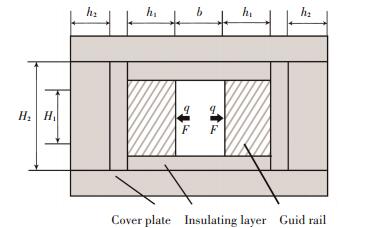
The mechanical model of bi-layer beam of electromagnetic launching rails under distribution force is shown in Fig. 4. In it the length of the beams is l=2 000 mm, the partial loads' action length l1 are separately 500 mm, 1 000 mm and 1 500 mm. The cross section dimension of rectangular launching tube is shown in Fig. 4.
|
Figure 4 Cross-section of electromagnetic rail launcher |
The upper beam (rails) section dimension are H1=30 mm, h1=10 mm, the lower beam (panels) section dimension are H2=50 mm, h2=20 mm. The upper beam is copper, its elastic modulus is E=110 GPa; the lower beam is nylon, its elastic modulus is E=28.3 GPa. The foundation constant between upper and lower beams is c1=3 MPa, the foundation constant between lower beam and fixed board is c2=6 MPa. The distribution load acted on upper beam is q=1.5 N/mm, concentrated load is F=500 N.
5.2 Establishment of Boundary ConditionsThe upper and lower beams are both simple beams and the boundary conditions are:
| $ {w_1}\left( 0 \right) = {w_1}\left| {_{x = 0}} \right. = 0,{{w''}_1}\left( 0 \right) = \frac{{{{\rm{d}}^2}{w_1}}}{{{\rm{d}}{x^2}}}\left| {_{x = 0}} \right. = 0 $ |
| $ {w_1}\left( l \right) = {w_1}\left| {_{x = l}} \right. = 0,{{w''}_1}\left( l \right) = \frac{{{{\rm{d}}^2}{w_1}}}{{{\rm{d}}{x^2}}}\left| {_{x = l}} \right. = 0 $ |
| $ {w_2}\left( 0 \right) = {w_2}\left| {_{x = 0}} \right. = 0,{{w''}_2}\left( 0 \right) = \frac{{{{\rm{d}}^2}{w_2}}}{{{\rm{d}}{x^2}}}\left| {_{x = 0}} \right. = 0 $ |
| $ {w_2}\left( l \right) = {w_2}\left| {_{x = l}} \right. = 0,{{w''}_2}\left( l \right) = \frac{{{{\rm{d}}^2}{w_2}}}{{{\rm{d}}{x^2}}}\left| {_{x = l}} \right. = 0 $ |
Put w1(0), w1″(0), w2(0), w2″(0) into Eq.(18), considering the boundary conditions at x=l, four equations can be obtained and w1′(0), w1"′(0), w2′(0), w2"′(0) calculated out, then put them into Eq.(19), the deflection of upper and lower beams as w1(x) and w2(x can be obtained, then the moment of upper and lower beam separately as M1(x and M2(x as well as the section max normal stress as σ1, max(x) and σ2, max(x) can be obtained by Eqs.(20) and (21).
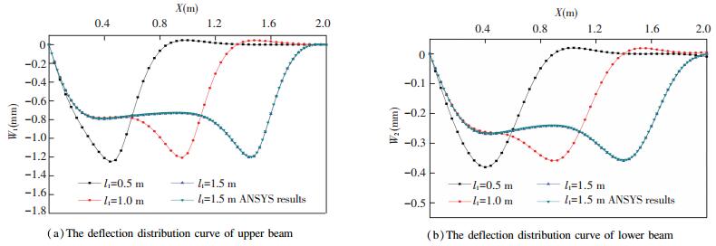
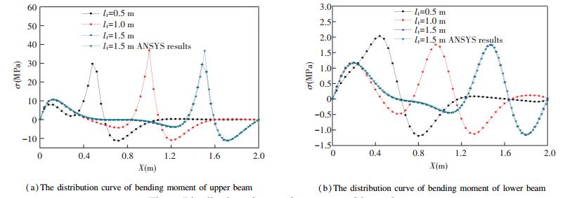
5.3 Calculation Result and AnalysisWhen li separately as 500 mm, 1 000 mm, 1 500 mm and 2 000 mm, the deflection curve are shown in Figs. 5 and 6. From the figure, it is obvious that the max deformation range of upper and lower beams are increasing along with the expansion of the action area of electromagnetic force and armature force. However, the value of max deflection is without obvious change. And the difference of stress value is because of the big difference of inertia moment between upper and lower beams.
|
Figure 5 Distribution of deflection for upper and lower beams |
|
Figure 6 Distribution of stress for upper and lower beams |
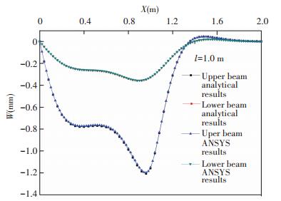
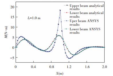
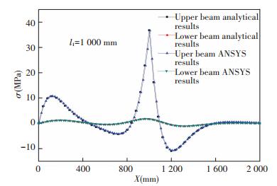
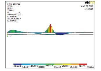
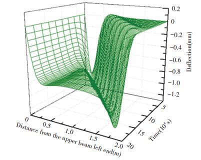
When li= 1 000 mm, the comparison with ANSYS value solution from deflection, moment and stress distribution curve of upper and lower beams are shown in Figs. 7-8 which can be found good coincidence. When li=1 000 mm, the stress distribution cloud maps from ANSYS are shown in Fig. 10 which certified the liability of analytical solution. The whole procedure of launching rails' (upper beams) deflection change when the armature runs at a speed of 1 000 m/s is shown in Fig. 11.
|
Figure 7 Comparison of analytical result and ANSYS result for upper and lower beams' deflection distribution |
|
Figure 8 Comparison of analytical result and ANSYS result for upper and lower beams' moment distribution |
|
Figure 9 Comparison of analytical result and ANSYS result for upper and lower beams' stress distribution |
|
Figure 10 Stress distribution nephogram at l1=1 000 mm |
|
Figure 11 The upper beam deflection changes with time |
5 Conclusions
The present work investigated the mechanical characteristics of rails and panels in a rectangular electromagnetic rail launcher. Major findings are summarized as follows.
1) In calculating the rigidness and strength, it is closer to practical reality to simulate the rails and panels as bi-layer elastic foundation beams rather than single-layer.
2) Under the electromagnetic force, the flexural rigidities of rails and panels and the elastic constants of two layers are the key parameters dictating the strengths and stresses of the rails and panels.
3) The current work develops an effective approach to analytically solve the mechanical analyses of bi-layer elastic foundation beams. Numerical simulations were also performed in ANSYS. Reasonable agreements were observed between the analytical calculations and the ANSYS results.
| [1] |
McNab I R, Beach F C. Naval Railguns. IEEE Transactions on Magnetics, 2007, 43(1): 463-468. DOI:10.1109/TMAG.2006.887446 (  0) 0) |
| [2] |
McNab I R, Stefani F, Crawford M, et al. Development of a naval railgun. IEEE Transactions on Magnetics, 2005, 41(1): 206-210. DOI:10.1109/TMAG.2004.839285 (  0) 0) |
| [3] |
Qiao Zhiming, Lei Bin, Lv qing'ao, et al. Analysis of the key technologies and development tendency of electromagnetic railguns. Journal of Gun Launch & Control, 2016, 37(2): 91-95. (in Chinese) DOI:10.19323/j.issn.1673-6524.2016.02.019 (  0) 0) |
| [4] |
Gu Gang, Xiang Yang, Zhang Jiange. The overview of the international electromagnetic launch technology research. Ship Science and Technology, 2007, 29(Supp. 1): 156-158. (in Chinese) (  0) 0) |
| [5] |
Liu Xiaoping. U.S. Navy electromagnetic rail gun prototype test. Modern Ship, 2011(4): 40-43. (in Chinese) (  0) 0) |
| [6] |
Army breakthrough research on the new sophisticated weapons[video]. http://news.cntv.com/world/20120229/124357.shtml 2012-2-29. U.S.
(  0) 0) |
| [7] |
Lin Lingshu, Yuan Weiqun, Zhao Ying, et al. Scaling method on electromagnetic railgun. High Power Laser and Particle Beams, 2016, 28(1): 66-71. (in Chinese) DOI:10.11884/HPLPB201628.015007 (  0) 0) |
| [8] |
Tan Sai, Liu Junyong, Zhang Xiao, et al. The numerical analysis methods of electromagnetic rail launcher with motion. Journal of Naval University of Engineering, 2016, 28(5): 46-50. (in Chinese) DOI:10.1109/TPS.2016.2605164 (  0) 0) |
| [9] |
Lou Yutao, Li Haiyuan, Li Baoming. Research on proximity effect of electromagnetic railgun. Defence Technology, 2016, 12(3): 223-226. DOI:10.1016/j.dt.2016.01.010 (  0) 0) |
| [10] |
Tan Sai, Liu Junyong, Zhang Xiao, et al. Finite element analysis of melt wave ablation in electromagnetic rail launcher armatures. Journal of Xi'An Jiaotong University, 2016, 50(3): 106-111. (in Chinese) DOI:10.7652/xjtuxb201603017 (  0) 0) |
| [11] |
Tian Zhenguo, Bai Xiangzhong, Yang Yang. Dynamic response of rail under a launching state of an electromagnetic rail. Journal of Vibration and Shock, 2012, 31(2): 10-14. (in Chinese) (  0) 0) |
| [12] |
Tian Zhenguo, Bai Xiangzhong, Yang Yang. The analysis of local contact stress on the side of rail when the electromagnetic rail is at a launching state. Chinese Journal of Solid Mechanics, 2011(1): 74-81. (in Chinese) (  0) 0) |
| [13] |
Xu W, Yuan W, Cheng W, et al. Uncertainty analysis with repeated launch in electromagnetic launch. High Voltage Engineering, 2016, 42(9): 2835-2842. (in Chinese) DOI:10.13336/j.1003-6520.hve.20160907018 (  0) 0) |
| [14] |
Lin Zhipeng, Liu Zhenxiang, Yang Dong, et al. Finite element/boundary element simulation of 3D rail gun with coupling method based on symmetry condition. Journal of Ordnance Equipment Engineering, 2016, 37(3): 42-44. (in Chinese) (  0) 0) |
| [15] |
Tan Sai, Liu Junyong, Zhang Xiao, et al. Numerical analysis method of magneitic-thermal coupling field in electromagnetic rail launchers with motion. Journal of Naval University of Engineering, 2016(B06): 56-60. (  0) 0) |
| [16] |
Tan Sai, Liu Junyong, Zhang Xiao, et al. Numerical simulation of dynamic launching in electromagnetic rail launcher. Journal of National University of Defense Technology, 2016, 38(6): 43-48. (in Chinese) (  0) 0) |
| [17] |
Tzeng J T. Structural mechanics of electromagnetic railguns. IEEE Transactions on Magnetics, 2005, 41(1): 246-250. DOI:10.1109/TMAG.2004.839828 (  0) 0) |
| [18] |
Johnson A J, Moon F C. Elastic waves and solid armature contact pressure in electromagnetic launchers. IEEE Transactions on Magnetics, 2006, 42(3): 422-429. DOI:10.1109/TMAG.2005.862105 (  0) 0) |
| [19] |
Xing Shuzhen. The static calculation of double continuous beam on discrete elastic supports. Journal of theChina Railway Society, 1994, 16(1): 80-86. (  0) 0) |
| [20] |
Zhang Haihua, Xiong Jun, Tan Zhiming. Bi-layer beams on elastic foundation with horizontal frictional resistance. Mechanics in Engineering, 2011, 33(4): 33-37. (in Chinese) (  0) 0) |
| [21] |
Kvznecov V I. Elastic Foundation. Beijing: Building Engineering Press, 1959. (in Chinese)
(  0) 0) |
 2018, Vol. 25


