2. Naval Vessel Technical Evaluation Center for Hull Strucutre Strength, Wuhan 430033, China
Under the influences of electrochemical corrosion, ocean organism adhered and non-metal impurities in metal materials, pitting corrosion damage usually exists in the hull plates. As the main structures of ship, the pitting corrosion of hull plates will lead to the ultimate bearing capacity of hull reduce dramatically, thus impacting the security of ship structures[1-2]. In recent years, as the cognition of pitting corrosion′s failure mechanism has been improved, more attentions have been paid to the impact of pitting corrosion to plate strength[3-5]. The statistical theory was used to analyse the impact of partial corrosion to plate buckling load, and the methods to calculate the critical pressure of plate′s instability were obtained[6]. The ultimate strength of ship structures under the condition of pitting corrosion was analysed through finite element analysis[7-8]. The relationships between distribution of pitting corrosion, positions, plate thickness and ultimate strength were obtained. Some researches on ultimate strength of steel plates with pitting corrosion carried out under experiment and finite element method[9-10]. The results showed that, in terms of plates owning just a single pitting corrosion, the position of pitting corrosion is unimportant for the ultimate compression strength, but extremely significant for post-buckling strength. Low carbon steel plates with pitting corrosion were analysed through nonlinear finite element analysis. One-side pitting corrosion resulted more in the decrease of compressive ultimate power when the thickness of pitting corrosion plate was the same as discovered, and many methods were taken to represent the level of pitting corrosion is imperfect[11-13].
Currently, in terms of the research on impacts of pitting corrosion to ultimate strength of plates, many researchers analyse the situations under axial load and many achievements have been obtained, while the research considering the influence of lateral load will be more useful[14]. As the axial ability bearing compression of bottom plate under horizontal hydrostatic pressure represents the safety level of the whole hull structure under hogging state. Therefore, the plate of real ship with pitting corrosion was taken as the object to analyse pitting characteristic parameters′ impact to the sensitivity of ultimate strength of plate by establishing mechanical and finite element model in this paper. Moreover, the concept of factor of rigidity reduction was proposed to appraise the level of plate′s pitting corrosion. Numerical finite element calculations were used to obtain the equation calculating the axial ultimate strength of plate under the condition of combined load.
2 Pitting Characteristic MatrixThere is still no effective method to precisely describe the characteristics of pitting corrosion due to the complicated distribution. To some extent, it is detrimental for research on pitting corrosion [15-16]. In order to solve this the plates of actual ship were taken as an example, the forms and positions of pitting corrosion were analysed in this paper. The concept of pitting characteristic matrix is proposed to study on the calculating methods of the ultimate strength of plates.
2.1 Pitting Corrosion FormsThe statistical data from actual ship of pitting corrosion shows that most of the shapes of pitting corrosion in bulk freighter are cone, while most are hemispheric in tankers, and most are echelon cone in military vessels[17]. The shapes of pitting corrosion of components such as ribs are usually spherical. Although the shapes are different in different structures and ships, they can be mainly divided into cone and hemisphere(as shown in Fig. 1).

|
Figure 1 Pitting forms |
In addition, research shows that the shapes of pitting corrosion just contribute little to the ultimate strength of components on condition of the same total volume[18]. Therefore, the cone and hemisphere shape of pitting corrosion could be transferred to cylinder shape in the same volume. The transformation equations as follows:
Cone shap→Cylinder shap:
| $ \frac{1}{3}{\left( {\frac{d}{2}} \right)^2}{h_C} = {\left( {\frac{d}{2}} \right)^2}{h_{cy}} $ |
Hemisphere shap→Cylinder shap:
| $ \frac{2}{3}{\left( {\frac{d}{2}} \right)^3} = {\left( {\frac{d}{2}} \right)^2}{h_{cy}} $ |
where hc is the depth of cone pitting corrosion, hs is the depth of hemisphere pitting corrosion, hcy is the depth of cylinder pitting corrosion, and d is the diameter of pitting corrosion.
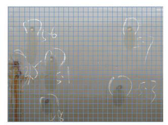
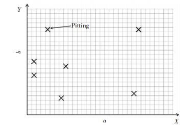
2.2 Distribution of Corrosion PittingThe data from collecting the situation of plates pitting corrosion of actual ships show corrosion distributed randomly in the plates under the influences of plate material situation (such as non-metal impurities and weld crack) and outer environment (such as temperature, humidity and PH value). According to the data, the pitting corrosion of above waterline is always one-side distributed, mainly on the outer side and with rarely perforating phenomenon, is shown in Fig. 2. While at the areas close to waterline, it is always two-side distributed. The pitting characteristic parameters could be divided into geometrical parameters and distribution parameters in order to describe random distribution of pitting corrosion accurately. Geometrical parameters include diameter of pitting corrosion d and depth of pitting corrosion h. Distribution parameters mean the position of pitting corrosion on the coordinate, as shown in Fig. 3.
|
Figure 2 Pitting distribution on ship plate |
|
Figure 3 Pitting distribution on coordinate system |
2.3 Pitting Characteristic Matrix Establishing
Pitting characteristic matrix was proposed in order to describe the shapes, sizes and positions of pitting corrosion of actual ship plates more precisely. The established steps as following:
Step 1 Take the middle surface of hull plate as coordinate planes, the length of plate as x axis, the width of plate as y axis, thus establishing in Dartesian coordinate system.
Step 2 Take the largest diameter c of pitting corrosion as a standard to zone the hull plates and show in Fig. 2. There is the number of f cells along the length and the number of g cells along the width of plate.
| $ \left\{ \begin{array}{l} f = {\rm{int}}\left[ {\frac{a}{c}} \right]{\rm{ }}\\ g = {\rm{int}}\left[ {\frac{b}{c}} \right] \end{array} \right. $ |
where "int" means down round-off number.
Step 3 Take the distance between neighbor pitting corrosion as l, which is within
Step 4 The distribution characteristic matrix of pitting corrosion could be gained after integrating the dates and equations.
| $ \mathit{\boldsymbol{A}}{\rm{ }} = \left( {\begin{array}{*{20}{c}} {{a_{11}}}&{ \ldots }&{{a_{1g}}}\\ \vdots&\vdots&\vdots \\ {{a_{f1}}}&{ \ldots }&{{a_{fg}}} \end{array}} \right){\rm{ }} $ |
where, if aij=0, means no-pitting and if aij=1, means pitting.
3 Sensitivity of Pitting Characteristic Factors on Ultimate StrengthWhen the hull plate loses its stability under combined loads, the corresponding strength is defined ultimate strength. As the mechanism of pitting characteristic parameters influencing the ultimate strength of plates is really complicated, it is necessary to analyze the sensitivity of pitting characteristic parameters to test the level of influence on the plate ultimate strength.
3.1 Sensitivity Analysis Model of Pitting ParametersThe accuracy of analysis of sensitivity based on statistics is effective and reliable. An approach of selecting sample within the scope of parameter value was introduced to achieve analysis and the specific principle, and the method can be found in Ref.[19]. In this approach, the sensitivity of ultimate strength under the condition of combined loads was calculated based on the mechanical model and finite element model. The main parameters contain pitting position, diameter and depth.
3.1.1 Mechanical modelThere are always beams, ribs and other support structures around hull plates, sometimes also longitudinal girder, cross beam, etc. Generally, the hull plates are more vulnerable than these structures, so the boundary of hull plates with pitting corrosion can be seen as simply support. Although the load of hull plates is complicated, it can be divided into two types: 1)The loads perpendicular to plate surface (such as gravity of cargo and hydrostatic pressure); 2)The axial loads on the plate[20] (such as interaction force between plates and plane stress). For the bottom plate, the main load is horizontal hydrostatic q and axial load T under total longitudinal bend. The mechanical model is shown in Fig. 4. The hydrostatic load is determined by ship draught, and in this case q=0.03 MPa, axial pre-compressing load T′=1 N/mm.

|
Figure 4 Mechanical model of hull plate |
3.1.2 Finite element model
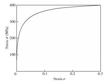
Considering shell element is greatly applicable in the finite element analysis of plate model with pitting corrosion[12], so S4R cell was adopted when building the finite element model in this paper. Moreover, S4R can greatly simulate the flexibility, plasticity and large deformation of shells and plates. In addition, during the process of finite element analysis and calculation in the way of risk method, nonlinear influences of geometrical and material are both considered. In the aspect of initial geometrical imperfections, the first-stage buckling was taken as the initial geometry deformation, and the amplitude w0=0.1β2t. Where
|
Figure 5 Relation between strain and stress of material |
3.2 Sensitivity Analysis
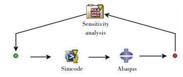
Sensitivity analysis represents the level of input variables′ influence as well as the contribution to output. The reason to study on sensitivity analysis is to confirm the influence level of pitting characteristics to the ultimate strength of plates under the setting condition of loading, thus gaining the fundamental knowledge for future research. Sensitivity analysis of pitting characteristic parameters is performed based on finite element analysis and Isight software through programming Umat program of Abaqus, by changing pitting positions, diameters and depths. The sensitivity calculation process is shown in Fig. 6.
|
Figure 6 Flowchart of sensitivity analysis |
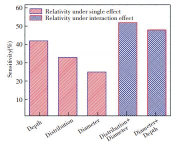
The model of sensitivity analysis is that: length of plate a=640 mm, width b=480 mm, thickness t=8 mm, elasticity modulus E=2.06×10⁵ MPa, Poisson ratio u=0.3. According to ships′ actual records, the diameter changes within [0 mm, 28 mm] and the depth changes within [0 mm, 4 mm], and the pitting corrosion position moves from the central to the edge. Owing to parameters have been normalized, the calculation results are not influenced by parameters′ dimensions. Therefore, the precision of sensitivity analysis has been improved a lot. The sensitivity analysis result of pitting corrosion parameters is shown in Fig. 7.
|
Figure 7 Results of sensitivity analysis |
As shown in Fig. 7, the depth of pitting corrosion is the most influential factor, followed by position and diameter. If considering pitting characteristic factors′ interaction, the influence of diameter and depth of pitting corrosion is the primary factor, followed by the effect between diameter and position of pitting corrosion.
4 Calculation of Ultimate LoadCorrosion volume and degree of pitting intensity are usually taken as the criteria to evaluate the ultimate strength of plate with pitting corrosion. Although those methods are applicable to some extent, rigidity reduction is more reasonable if considering the thin-wall effects and position of pitting corrosion. Therefore, the concept of rigidity reduction factor is proposed to calculate the ultimate load of hull plates with pitting corrosion based on pitting characteristic matrix.
4.1 Calculation of Rigidity Reduction FactorThe essence of pitting corrosion influences on the strength of plates is reducing the stiffness of plates. Given the random distribution of pitting corrosion can decentralize the stiffness and the flexibility β of plates is an important parameter to reflect the buckling strength of plates[21]. The hull plate with pitting corrosion is taken as thickness-changing plate along with width direction in this paper. The method to calculate rigidity reduction factor λ is shown as follows:
Step 1 Based on pitting characteristic matrix, the volume of plate in a cell is V=tc2, the equivalent thickness ti in each unit along the width of hull plate is
| $ {t_i} = t - \frac{{\sum\limits_{i = 1}^f {\pi {a_i}{h_i}{{\left( {\frac{{{d_i}}}{2}} \right)}^2}} }}{{ac}} $ |
where ai is the element in distribution characteristic matrix, hi is pitting depth, and di is pitting diameter.
Step 2 The stiffness of hull plate after pitting corrosion is
| $ D' = E\left( {\sum\limits_{i = 1}^{{\rm{ }}f} {} \left( {c{t_i}Z_i^2 + \frac{{ct_i^3}}{{12}}} \right) - \frac{{{{\left( {\sum\limits_{i = 1}^{{\rm{ }}f} {} c{t_i}Z_i^2} \right)}^2}}}{{\sum\limits_{i = 1}^{{\rm{ }}f} {c{t_i}{Z_i}} }}} \right) $ |
where Zi is the height centroid of unit width.
Step 3 The initial stiffness of hull plate is
| $ D = EI $ |
where I is the inertia moment of marine plate before pitting corrosion.
Step 4 The rigidity reduction factor of hull plate is
| $ \lambda = 1 - \frac{{D'}}{D} $ |
It is necessary to verify the validity of rigidity reduction factor method before it is used to calculate the ultimate strength of hull plates with pitting corrosion. In this case, the axial ultimate load of actual hull plate is calculated in the way of rigidity reduction and actual pitting corrosion situation respectively, based on established mechanical model and finite element model. The specific parameters of hull plates are shown in Table 1.
| Table 1 Parameters of actual ship structural plate |
Distribution characteristic matrix of pitting corrosion of hull plates is
| Table 2 Geometrical elements of pitting corrosion (mm) |
Based on the data from Tables 1 and 2, the axial load-displacement curve for the node which displacement is the largest in pitting plate has been obtained by different calculations methods through finite element under the horizontal uniform load q=0.03 MPa, and is shown in Fig. 8.

|
Figure 8 Axial compression load-displacement curves of pitting plate |
As shown in Fig. 8, the trend between the method of rigidity reduction and pitting corrosion direct simulation is identical before reaching the summit. The largest axial load of pitting plate obtained by rigidity reduction calculation Tc=241.82 N/mm, while in the method of pitting simulation calculation Tc′=234.96 N/mm, and the deviation between them is 2.92%. Therefore, the method to evaluate pitting corrosion damage degree by rigidity reduction is feasible and reliable.
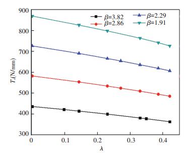
4.3 Calculating Formula of Ultimate StrengthThe validity of rigidity reduction factor method has been demonstrated, and the evaluation formula of ultimate strength of hull plates with pitting corrosion under combined load is proposed based on finite element numerical calculation. According to Classification Rules of Steel Sea-going Vessel from CCS, hull plates would be fixed or replaced when the level of pitting corrosion is reached. So that the actual range of rigidity reduction factor λ is [0, 0.48) and the thickness range of actual hull plates is always [6 mm, 12 mm]. The changing rule between axial ultimate load Tc and rigidity reduction factor λ under different flexibility of β when the horizontal hydrostatic pressure q=0.03 MPa is obtained based on series of finite element numerical calculation, and shown in Fig. 9.
|
Figure 9 Relation between Tc and λ under different flexibility |
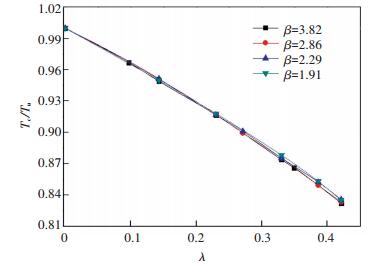
As shown in Fig. 9, the dimension of plate has a remarkable impact on the axial ultimate load. The ultimate strength reduction ratio Tc/Tu (where Tc is the axial ultimate load considering pitting and Tu is the axial ultimate load without pitting) was taken to weigh the damage degree of plate pitting to remove the effect of dimension. The changing trend between Tc/Tu and λ is shown in Fig. 10. As been shown, the geometrical sizes of plate are less influential to the ultimate strength reduction ratio Tc/Tu, thus the purpose of removing the size effect of plates has been achieved.
|
Figure 10 Relation between Tc/Tu and λ under different flexibility |
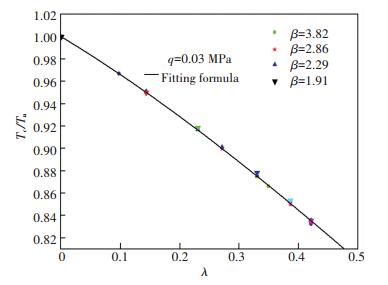
The relationship between ultimate strength reduction ratio Tc/Tu and rigidity reduction factor λ is obtained based a series of finite element numerical calculations, and the rule was shown in Fig. 11. The evaluating formula of ultimate strength of hull plates with pitting corrosion under condition of horizontal hydrostatic pressure q=0.03 MPa was obtained by regression analysis, and as follows:
|
Figure 11 Relation between Tc/Tu and λ under numerical calculation and fitting formula |
| $ \frac{{{T_c}}}{{{T_u}}} = 0.082{\rm{ }}66{\lambda ^3} - 0.201{\rm{ }}4{\lambda ^2} - 0.320{\rm{ }}9\lambda + 1 $ | (1) |
In terms of the formula of ultimate strength of hull plates with pitting corrosion, the correlation coefficient R2 is 0.999 8, and the standard deviation S is 9.75×10⁻⁵. The maximum deviation between Eq.(1) and finite element calculations is 3.25%. Therefore, applying the Eq.(1) to evaluate the ultimate strength of hull plates in that case is reliable and applicable. The evaluating formula of ultimate strength of hull plates with pitting corrosion under different horizontal hydrostatic load would be obtained by the method presented in the paper. However, for those heavy pitting corrosion with holes, more researches need to be performed because of the hull plate′s failure mode has been transformed.
5 ConclusionsThe concept of pitting characteristic matrix has been proposed based on the analysis of the characteristic factors of actual hull plates with pitting corrosion as well as sensitivity of pitting parameters analyzed. The method to estimate the ultimate strength of hull plates with pitting corrosion under certain horizontal hydrostatic load has been carried out by the way of ultimate strength reduction ratio based on the sensitivity analysis and pitting characteristic matrix. The formula to evaluate the ultimate strength of hull plates with pitting corrosion which is proven to be feasible has been presented. The conclusions can be drawn as follows:
1) The depth of pitting is the most influential factor to the ultimate strength of hull plates with pitting corrosion under the condition of single influence of factor, while the inter-influence between diameter and depth of pitting becomes the most influential factor, followed by inter-influence between diameter and distribution of pitting when considering interactive influence between factors.
2) The method to estimate the pitting corrosion′s influence on ultimate strength of hull plates in the way of rigidity reduction is feasible and rational. The formula of calculating ultimate strength of hull plate with pitting corrosion that has been obtained under combined loads in the way of rigidity reduction is reliable and applicable in engineering. Due to the standard deviation S is 9.75×10⁻⁵, and the correlation coefficient R2 is 0.999 8, the formula could be the criteria and relevant standard to calculate the ultimate strength of hull plates with pitting corrosion.
3) The concepts of pitting characteristic matrix and rigidity reduction factor are proposed in this paper, which develop a new way to study the pitting damage. The formula is established to evaluate the degree pitting damage could make a great contribution to further research in this area.
| [1] |
Bhandari J, Khan F, Abbassi R, et al. Modeling of pitting corrosion in marine and offshore steel structures-A technical review. Journal of Loss Prevention in the Process Industries, 2015, 37: 39-62. DOI:10.1016/j.jlp.2015.06.008 (  0) 0) |
| [2] |
Wang Renhua, Fang Yuanyuan, Lin Zhendong, et al. Multi-scale analysis of residual strength of offshore platforms with pitting corrosion. Engineering Mechanics, 2016, 33(1): 238-245. DOI:10.6052/j.issn.1000-4750.2014.06.0524 (  0) 0) |
| [3] |
Huang Y, Zhang Y, Liu G, et al. Ultimate strength assessment of hull structural plate with pitting corrosion damnification under biaxial compression. Ocean Engineering, 2010, 37(17/18): 1503-1512. DOI:10.1016/j.oceaneng.2010.08.001 (  0) 0) |
| [4] |
Ok D, Pu Y, Incecik A. Artificial neural networks and their application to assessment of ultimate strength of plates with pitting corrosion. Ocean Engineering, 2007, 34(17/18): 2222-2230. DOI:10.1016/j.oceaneng.2007.06.007 (  0) 0) |
| [5] |
Nakai T, Matsushita H, Yamamoto N. Effect of pitting corrosion on strength of web plates subjected to patch loading. Thin-Walled Structures, 2006, 44(1): 10-19. DOI:10.1016/j.tws.2005.09.004 (  0) 0) |
| [6] |
Paik J K, Lee J M, Ko M J. Ultimate compressive strength of plate elements with pit corrosion wastage. Proceedings of the Institution of Mechanical Engineering, Part M: Journal of Engineering for the Maritime Environment, 2003, 217(4): 185-200. DOI:10.1243/147509003322596059 (  0) 0) |
| [7] |
Nakai T, Matsushita H, Yamamoto N, et al. Effect of pitting corrosion on local strength of hold frames of bulk carriers. Marine Structures, 2004, 17(5): 403-432. DOI:10.1016/j.marstruc.2004.10.001 (  0) 0) |
| [8] |
Zhang Y, Huang Y, Zhang Q, et al. Ultimate strength of hull structural plate with pitting corrosion damnification under combined loading. Ocean Engineering, 2016, 116: 273-285. DOI:10.1016/j.oceaneng.2016.02.039 (  0) 0) |
| [9] |
Stewart M G, Al-Harthy A. Pitting corrosion and structural reliability of corroding RC structures: Experimental data and probabilistic analysis. Reliability Engineering and System Safety, 2008, 93(3): 373-382. DOI:10.1016/j.ress.2006.12.013 (  0) 0) |
| [10] |
Ahn J-H, Cheung J-H, Lee W-H, et al. Shear buckling experiments of web panel with pitting and through-thickness corrosion damage. Journal of Constructional Steel Research, 2015, 115: 290-302. DOI:10.1016/j.jcsr.2015.08.032 (  0) 0) |
| [11] |
Jiang Xiaoli, Guedes S C. Nonlinear FEM analysis of pitted mild steel square plate subjected to in-plane compression. Journal of Ship Mechanics, 2009, 13(3): 398-405. (  0) 0) |
| [12] |
Vodka O. Computation tool for assessing the probability characteristics of the stress state of the pipeline part defected by pitting corrosion. Advances in Engineering Software, 2015, 90: 159-168. DOI:10.1016/j.advengsoft.2015.08.012 (  0) 0) |
| [13] |
Shekari E, Khan F, Ahmed S. A predictive approach to fitness-for-service assessment of pitting corrosion. International Journal of Pressure Vessels and Piping, 2015, 137: 13-21. DOI:10.1016/j.ijpvp.2015.04.014 (  0) 0) |
| [14] |
Luo Gang, Wu Guomin, Tang Gang, et al. Analyze the influence of lateral pressure on the ultimate strength of the stiffen plate. Journal of Wuhan University of Technology, 2014, 38(6): 1400-1404. DOI:10.3963/j.issn.2095-3844.2014.06.049 (  0) 0) |
| [15] |
Yu L, François R, Dang V H, et al. Distribution of corrosion and pitting factor of steel in corroded RC beams. Construction and Building Materials, 2015, 95: 384-392. DOI:10.1016/j.conbuildmat.2015.07.119 (  0) 0) |
| [16] |
Soltis J. Passivity breakdown pit initiation and propagation of pits in metallic materials review. Corrosion Science, 2015, 90: 5-22. DOI:10.1016/j.corsci.2014.10.006 (  0) 0) |
| [17] |
Chen Debin, Hu Yulong, Chen Xuequn. Progress of microbial influenced corrosion in warship. Journal of Naval University of Engineering, 2006, 18(1): 79-84. DOI:10.3969/j.issn.1009-3486.2006.01.017 (  0) 0) |
| [18] |
Zhang Yan, Huang Yi, Liu Gang. Ultimate shear strength of ship structural plate with pitting corrosion damnification. Journal of Ship Mechanics, 2013, 17(1/2): 102-111. DOI:10.3969/j.issn.1007-7294.2013.hl.013 (  0) 0) |
| [19] |
Hua Lin, Wu Fan, Wang Jin, et al. Structural optimization of ring-stiffened circular cylindrical shell based on sensitivity analysis. Ship Engineering, 2015, 37(5): 15-18. DOI:10.13788/j.cnki.cbgc.2015.05.015 (  0) 0) |
| [20] |
Wu Fan, Zhu Xi, Mei Zhiyuan. Structural Mechanics for Ships. Beijing: National Defense Industry Press, 2010.
(  0) 0) |
| [21] |
Huang Kezhi. Theory of Plate and Shell. Beijing: Tsinghua University Press, 1987.
(  0) 0) |
 2018, Vol. 25


