The square unit and its combination mechanism have many advantages, such as reusability, easy to assemble, small size after folding, and covering a large area after being unfolded. Therefore, since the 1960s, it has been widely used in aerospace[1-3], architecture[4-5], biology[6], and other fields, specifically in spatial stretching arms, deploying antenna reflectors, deploying domes, contracting stomachs treatment instrument, and so on.
The movement process of the square unit and its combined mechanism includes three phases: the start-up phase, the unfolding moving phase, the unfolding finish and locking phase. In the second phase, since the deployable mechanism is composed of a large number of intermediate motion subunits, thus motion pair clearance, created by frictional wear and manufacturing errors, will cause contact collisions between the motion auxiliary elements. Such resulting contact collision force affects movement synchronization and deployment accuracy between different components, and eventually reduces the available life of mechanism. Therefore, in order to ensure the smooth movement and reliable loading of the deployable mechanism, it is necessary to explore its kinematics precision and dynamic characteristics. The Gonthier contact force model and the modified Coulomb friction model were utilized by Li[7] to analyze the contact collision problem of a scissor-type linear array deployable structure. Li [8] considered the contact collision and friction problems of the deployable mechanism during the movement deploying process, and comprehensively analyzed the influence of the position of the clearance joint, the clearance value, and the number of clearance on the dynamic characteristics of the scissor-developing mechanism. In addition, based on linear elastic analysis and substructure methods, Li[9] studied the effect of unit number, deployment angle, and rod length on structural instability after completion of deployment, and the analysis results are conducive to reducing budgets and improving computational efficiency. Hu[10] studied the influence of the joint clearance and the alternating hot load on the dynamic characteristics of large scale space-based space deployable structures during the unfolding movement.
In this paper, the elastic deformation of the square expandable mechanism member was not taken into account. The clearance was introduced into the movement pair of the mechanism. The normal contact force between pin and the pin hole of the joint was established by using the Flours contact force model[11-13], and the tangential contact force between them was obtained from the LuGre friction model[14-15]. Finally, by using the dynamic equations of the square combination mechanism, a dynamic model of the square combined mechanism containing the joint clearance was established. The Baumgarte stability constraint method was used to avoid the problem of constraint violation in the integration process[16-17].
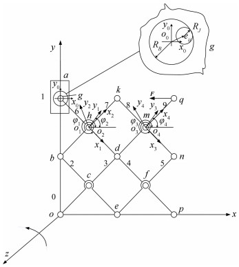
2 Dynamic Equations of Square Combination Mechanism 2.1 Square Combination MechanismThe square unit and its combination mechanism are composed of four scissor units, which are hinged by a movement joint. The Cartesian coordinate system of the square unit combinational mechanism is established, as shown in Fig 1.
|
Fig.1 Square combination mechanism with clearance |
The bars numbers are identified by 0 (frame), 1 (slide), 2, 3, 4, 5, 6, 7, 8, and 9.
Motion pair numbers are identified by o, a, b, c, d, e, f, g, h, k, m, n, p, q. Among these pairs, only pair a is a moving pair[18-19], and the other pairs are rotating pairs.
Without affecting the mathematical description of the square combination mechanisms' model, in order to facilitate the investigation, the motion pair g is locally enlarged, rod 6 and rod 7 are relatively rotated to each other around pin h. Rod 6 and rod 7 are equally divided by o1(o2), and the lateral horizontal load of point q is F=100 N.
The length of all poles of the square combination mechanism is 350 mm. Assume the square combination mechanism shown in Fig. 1 is a rigid body, and rods are axis of the connected local coordinate system xioiyi (i=1, 2, 3, 4). Define xoy as a global coordinate system, the center of mass of the rod and the slider o0, o1, o2, o3, o4 as the origin of the local coordinate system, and φi as the positive angle between the vector x on the global coordinate system and the vector xi on the local coordinate system. Then the position of component can be expressed as
| $ {\mathit{\boldsymbol{q}}_i} = \left[ {\mathit{\boldsymbol{x}},\mathit{\boldsymbol{y}},\phi } \right]_i^{\rm{T}} $ | (1) |
The complete general coordinates of all members of the square assembly are given as
| $ \mathit{\boldsymbol{q}} = {\left[ {\left[ {\mathit{\boldsymbol{x}},\mathit{\boldsymbol{y}},\phi } \right]_1^{\rm{T}},\left[ {\mathit{\boldsymbol{x}},\mathit{\boldsymbol{y}},\phi } \right]_2^{\rm{T}}, \cdots ,\left[ {\mathit{\boldsymbol{x}},\mathit{\boldsymbol{y}},\phi } \right]_n^{\rm{T}}} \right]^{\rm{T}}} $ | (2) |
The complete constraint equation for all motion pairs of square combination can be expressed as
| $ \mathit{\boldsymbol{ \boldsymbol{\varPhi} }}\left( {\mathit{\boldsymbol{q}},t} \right) = 0 $ | (3) |
The speed equation of the square combination mechanism can be obtained by the first derivative of the time t in Eq. (3), and the acceleration equation can be computed by the second order of the time t in Eq.(3). The augmentation method can be used to describe motion pair's counter-force constraints of square combination mechanism, and then determine its kinematic differential equation:
| $ \left\{ \begin{array}{l} \mathit{\boldsymbol{M\ddot q}} + \mathit{\boldsymbol{ \boldsymbol{\varPhi} }}_q^{\rm{T}}\mathit{\boldsymbol{\lambda }} = \mathit{\boldsymbol{Q}}\\ \mathit{\boldsymbol{ \boldsymbol{\varPhi} }}\left( {\mathit{\boldsymbol{q}},t} \right) = 0 \end{array} \right. $ | (4) |
where Φq is Jacobian matrix of the combined mechanism, M is the mass matrix of the square combined mechanism,
| $ \left[ {\begin{array}{*{20}{c}} \mathit{\boldsymbol{M}}&{\mathit{\boldsymbol{ \boldsymbol{\varPhi} }}_q^{\rm{T}}}\\ {{\mathit{\boldsymbol{ \boldsymbol{\varPhi} }}_q}}&0 \end{array}} \right]\left[ {\begin{array}{*{20}{c}} {\mathit{\boldsymbol{\ddot q}}}\\ \lambda \end{array}} \right] = \left[ {\begin{array}{*{20}{c}} \mathit{\boldsymbol{Q}}\\ {\gamma - 2\alpha \mathit{\boldsymbol{ \boldsymbol{\dot \varPhi} }} - {\beta ^2}\mathit{\boldsymbol{ \boldsymbol{\varPhi} }}} \end{array}} \right] $ | (5) |
In the Eq.(5),
The kinematics characteristics of the rotating pair with clearance considered is an important prerequisite to explore the impact of contact collision on the dynamic performance of the square combination mechanism.
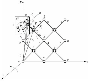
If the clearance is taken into account in the joint g of square combination mechanism, when the contact between pin hole i and pin j is in contact, as shown in Fig. 2, the center of local coordinate system xioiyi and xjojyj coincide with the center of pin hole i and the centroid of pin j respectively.
|
Fig.2 Square combination mechanism with clearance |
In Fig. 2, rjQ and riQ are the position vectors of the center of pin hole oi and the center of pin oj in the global coordinate system, and e represents the eccentricity of the two center points.
| $ \mathit{\boldsymbol{e}} = \mathit{\boldsymbol{r}}_j^Q - \mathit{\boldsymbol{r}}_i^Q $ | (6) |
When the pin hole contacts the pin, the normal vector of the contact surface between the pin hole and the pin is given by
| $ \mathit{\boldsymbol{n}} = \frac{\mathit{\boldsymbol{e}}}{e} $ | (7) |
where
Once c represents the clearance between the pin hole and the pin, then c=RB-RJ. Here RB and RJ are the radius of the pin hole and the pin respectively.
The contact deformation amount between the pin hole and the pin is
| $ \delta = e - c $ | (8) |
In order to more clearly express the contact state between the pin hole and the pin, the total contact deformation δ is used to facilitate judgment. When δ≥0, the pin hole and the pin element are in separated state; when δ≥0, the pin hole and the pin are in contact. For the respective contact points Qi and Qj of pin hole and the pin in a joint with clearance, after contact, their position vector at the global coordinate system xoy can be described by the following formula:
| $ \left\{ \begin{array}{l} \mathit{\boldsymbol{r}}_i^Q = {\mathit{\boldsymbol{r}}_i} + {T_i}\mathit{\boldsymbol{s}}_i^Q + {R_i}\mathit{\boldsymbol{n}}\\ \mathit{\boldsymbol{r}}_j^Q = {\mathit{\boldsymbol{r}}_j} + {T_j}\mathit{\boldsymbol{s}}_j^Q + {R_j}\mathit{\boldsymbol{n}} \end{array} \right. $ | (9) |
where ri and rj are position vectors of centroids of pin holes i and pins j in the global coordinate system respectively, Ti and Tj are transfer matrix between local coordinates and global coordinate system, siQ and sjQ are position vectors of contact points Qi and Qj for pin holes and pins at the local coordinate system xioiyi and xjojyj respectively, and riQ and rjQ represent position vectors of contact points Qi and Qj at the global coordinate system xoy respectively.
Calculating the first derivative of time t with respect to Eq.(9), the relative contact speed between pin hole and pin when considering clearance can be obtained. νN and νt are the normal and tangent vectors of relative contact velocity, respectively:
| $ \left\{ \begin{array}{l} {v_N} = {\left( {\mathit{\boldsymbol{\dot r}}_j^Q - \mathit{\boldsymbol{\dot r}}_i^Q} \right)^{\rm{T}}}\mathit{\boldsymbol{n}}\\ {v_t} = {\left( {\mathit{\boldsymbol{\dot r}}_j^Q - \mathit{\boldsymbol{\dot r}}_i^Q} \right)^{\rm{T}}}\mathit{\boldsymbol{t}} \end{array} \right. $ | (10) |
where the tangent vector t of the contact surface is obtained from the normal vector n by counterclockwise rotating 90°,
Hertz's contact theory has a disadvantage of failing to express the energy transfer during contact collision[20]. Flores solved this problem and proposed a nonlinear contact-damping collision force model:
| $ {F_N} = K{\delta ^n}\left[ {1 + \frac{{8\left( {1 - {c_r}} \right)}}{{5{c_r}}}\frac{{\dot \delta }}{{{{\dot \delta }_0}}}} \right] $ | (11) |
where δ represents contact deformation,
| $ K = \frac{4}{{3{\rm{ \mathit{ π} }}\left( {{\sigma _i} + {\sigma _j}} \right)}}{\left( {\frac{{{R_i}{R_j}}}{{{R_i} - {R_j}}}} \right)^{\frac{1}{2}}} $ | (12) |
where
The friction phenomenon is indispensable when analyzing the contact collision between relative moving bodies. In order to capture the slip phenomenon in the friction between the contact bodies, as well as to avoid the energy increase phenomenon during the contact process of the contact body, LuGre friction model was adopted. The contact force calculation formula for this model is
| $ \begin{array}{l} {F_t} = \left\{ {{\sigma _0}z\left[ {1 - \frac{{{\sigma _1}\left| {{\nu _t}} \right|}}{{{\mu _k} + \left( {{\mu _s} - {\mu _k}} \right){e^{ - \left| {\frac{{{\nu _t}}}{{{\nu _s}}}} \right|\gamma }}}}} \right] + } \right.\\ \;\;\;\;\;\;\;\left. {\left( {{\sigma _1} + {\sigma _2}} \right){\nu _t}} \right\}{F_n} \end{array} $ | (13) |
In Eq.(13)[21-22], Fn represents normal contact force, σ0 is stiffness coefficient of the bristles, σ1 denotes microscopic damping coefficient, σ2 is viscous friction coefficient, z is average deformation of the bristles, μk is dynamic friction coefficient, μs is static friction coefficient, νs is Stribeck velocity, νt is tangent vectors of relative contact velocity, and γ denotes index parameters which is generally taken as 2.
The LuGre model not only describes the slip phenomenon in friction, but also avoids the increase in energy of the contact body during the collision process, which can reflect the hinge gap friction phenomenon more truthfully.
4 Dynamic Analysis of Square Combination MechanismIn order to verify the rationality of the dynamics model and the mechanical model of the square combined mechanism with clearance, a numerical example was demonstrated to verify it. The square combination mechanism consists of homogenous alloy rods and remarks the length of each rod by l=350 mm. The mass of each rod is 2.8 kg, and the mechanism applies a driving force at the hinge point q.
Radius of the pin hole and the pin is 3.75 mm, elastic modulus of the pin hole and the pin's material is Ei=Ej=206.8 GPa, Poisson's ratio is υi=υj=0.32, density is ρ=7.8 g/cm3, cf=0.12.
In order to predict the dynamic characteristics of square combination mechanism with clearance, four physical quantities of square combination mechanism member can be used to determine the dynamic characteristic change, which are displacement, speed, acceleration, and counter-force of joint.
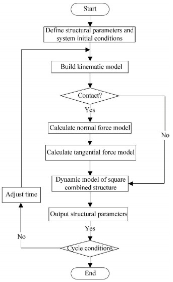
The dynamic analysis process of the square combination mechanism is shown in Fig. 3. Firstly, define initial conditions of movement and properties of the motion pair clearance on the basis of giving structural parameters of the square combination mechanism. Then, build construct kinematics model of the square combination mechanism that considers clearance. Finally, determine the contact state of pin hole and pin, and select corresponding model.
|
Fig.3 Flow chart of dynamic analysis |
When the clearance values fall within the 0.25 mm-0.5 mm interval, the variation trends of dynamic characteristics of joint g are as shown in Figs. 4-9.

|
Fig.4 Displacement response of the centroid of rod 6 with clearance size 0.25 mm and ideal joint |
|
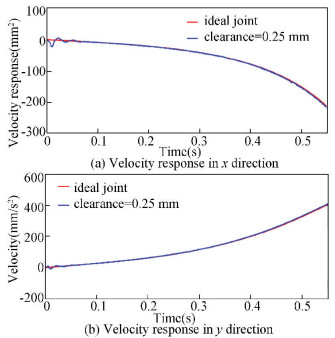
Fig.5 Velocity response of the centroid of rod 6 with clearance size 0.25 mm and ideal joint |
|
Fig.6 Acceleration response of the centroid of rod 6 with clearance size 0.25 mm and ideal joint |
|
Fig.7 Displacement response of the centroid of rod 6 with clearance size 0.25 mm and 0.5 mm |

|
Fig.8 Velocity response of the centroid of rod 6 with clearance size 0.25mm and 0.5mm |
|
Fig.9 Acceleration response of the centroid of rod 6 with clearance size 0.25 mm and 0.5 mm |
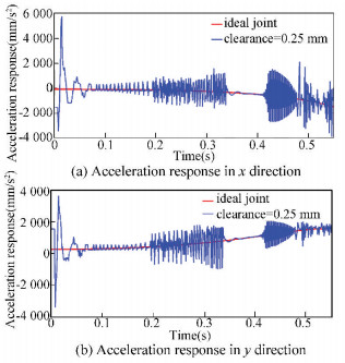
As shown in Fig. 4, for the displacement curve, the trajectories of ideal square deployable mechanism and clearance-containing square mechanism basically coincide. From Fig. 5, it can be seen that, if consider the clearance effect, the centroid velocity of bar 6 transiently fluctuates at the initial movement stage, but the overall trend of movement is stable, and the speed of the square combination member mechanism is less affected by the joint clearance. It can be seen from Fig. 6, with respect to the ideal mechanism, high-frequency oscillation occurs in the acceleration curve of mechanisms with clearances. This feature is correlated with mechanisms′ stability and movement accuracy. In Figs. 4-6, the external load is acting in x direction. Compared with x direction, the physical quantities in y direction, such as displacement, velocity, and acceleration of the centroid of connecting rod, are much more consistent with the ideal curves.
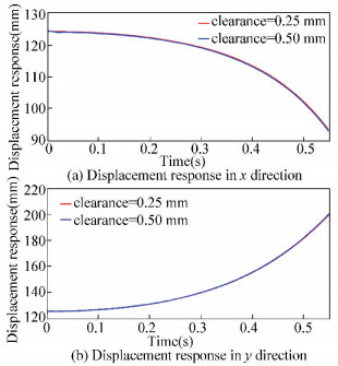
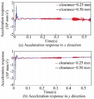
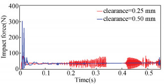
Differences can be identified from the comparison of the square mechanisms′ dynamic characteristics when the clearance value is 0.25 mm and 0.5 mm: as shown in Fig. 7 and Fig. 8, the influence of the clearance value on displacement and speed is not significant; in Fig. 9 and Fig. 10, as the clearance value increases, the acceleration amplitude and the contact force amplitude of the square mechanism gradually increase, notably, the value increases about 3 times in the initial stage. It can be concluded that, with continuing increase of clearance value, the dynamic performance of the square mechanism will subject to further deterioration until failure.
|
Fig.10 Impact force of the centroid of rod 6 with clearance size 0.25 mm and 0.5 mm |
5 Conclusions
(1) Based on the contact-separation-collision process, the clearance effect of joint was successfully introduced into the dynamic model of square deployable mechanism. The contact collision force was calculated by using the Flores model and the LuGre friction model respectively. In addition, the Baumgarte stability constraint method was utilized to effectively avoid constraint violations produced in integration process.
(2) The investigation of the dynamic characteristics of square deployable mechanism with clearance shows that the effect pairs of joint clearance needs to be take into account in mechanism dynamics calculation. Fig. 6 displays that a high-frequency oscillation characteristic appears on the acceleration curve of a mechanism with clearance rather than an ideal mechanism, and then the oscillation process converts to a smooth movement between 0.34 s and 0.42 s. This phenomenon indicates that the element movement of revolute pair with clearance converts from continuous collision to separate contact in this period of time.
(3) By the analysis of joints′ clearance values at 0.25 mm and 0.5 mm respectively, it can be seen that, with the increase of the clearance value, the dynamic curve of square expandable mechanism varied in much wide range, and the fluctuation amplitude was much larger. Moreover, it can be predicted that with further increase of clearance value, the collision process will be more severe until structural fail.
| [1] |
Puig L, Barton A, Rando N. A review on large deployable structures for astrophysics missions. Acta Astronautica, 2010, 67(1-2): 12-26. DOI:10.1016/j.actaastro.2010.02.021 (  1) 1) |
| [2] |
Chu Z R, Deng Z Q, Qi X Z, et al. Modeling and analysis of a large deployable antenna structure. Acta Astronautica, 2014, 95(1): 51-60. DOI:10.1016/j.actaastro.2013.10.015 (  1) 1) |
| [3] |
Zhao J S, Wang J Y, Chu F L, et al. Structure synthesis and statics analysis of a foldable stair. Mechanism & Machine Theory, 2011, 46(7): 998-1015. DOI:10.1016/j.mechmachtheory.2011.02.001 (  1) 1) |
| [4] |
Gantes C J. Deployable Structures:Analysis and Design. Southampton: WIT Press, 2001.
(  1) 1) |
| [5] |
Chen Y, Feng J, Zhang Y T. A necessary condition for stability of kinematically indeterminate pin-jointed structures with symmetry. Mechanics Research Communications, 2014(60): 64-73. DOI:10.1016/j.mechrescom.2014.06.004 (  1) 1) |
| [6] |
Hachem C, Hanaor A, Karni E. Evaluation of biological deployable systems. International Journal of Space Structures, 2005, 20(4): 189-200. DOI:10.1260/026635105775870260 (  1) 1) |
| [7] |
Li B, Wang S, Yuan R, et al. Dynamics analysis of linear array deployable structure based on scissor-like element considering joint clearance. Chinese Space Science & Technology, 2016, 36(3): 41-9. (  1) 1) |
| [8] |
Li B, Wang S M, Makis V, et al. Dynamic characteristics of planar linear array deployable structure based on scissor-like element with differently located revolute clearance joints. Proceedings of the Institution of Mechanical Engineers Part C:Journal of Mechanical Engineering Science, 2017, 232(10): Online. DOI:10.1177/0954406217710277 (  1) 1) |
| [9] |
Li B, Wang S M, Zhi C J, et al. Analytical and numerical study of the buckling of planar linear array deployable structures based on scissor-like element under its own weight. Mechanical Systems & Signal Processing, 2017, 83: 474-488. DOI:10.1016/j.ymssp.2016.06.025 (  1) 1) |
| [10] |
Hu H, Tian Q, Zhang W, et al. Nonlinear dynamics and control of large deployable space structures composed of trusses and meshes. Advances in Mechanics, 2013, 43(4): 390-414. DOI:10.6052/1000-0992-13-045 (  1) 1) |
| [11] |
Flores P, Ambrósio J, Claro J C P, et al. Kinematics and Dynamics of Multibody Systems with Imperfect Joints. Springer, 2008. (  1) 1) |
| [12] |
Flores P, Koshy C S, Lankarani H M, et al. Numerical and experimental investigation on multibody systems with revolute clearance joints. Nonlinear Dynamics, 2011, 65(4): 383-398. DOI:10.1007/s11071-010-9899-8 (  1) 1) |
| [13] |
Zheng E, Zhu R, Zhu S, et al. A study on dynamics of flexible multi-link mechanism including joints with clearance and lubrication for ultra-precision presses. Nonlinear Dynamics, 2016, 83(1-2): 137-159. DOI:10.1007/s11071-015-2315-7 (  1) 1) |
| [14] |
Canudas de Wit C, Olsson H, Astrom K J, et al. A new model for control of systems with friction. IEEE Transactions on Automatic Control, 1995, 40(3): 419-425. DOI:10.1109/9.376053 (  1) 1) |
| [15] |
Makkar C, Dixon W E, Sawyer W G, et al. A new continuously differentiable friction model for control systems design. IEEE/ASME International Conference on Advanced Intelligent Mechatronics. Proceedings. Piscataway:IEEE, 2005, 600-605. (  1) 1) |
| [16] |
Baumgarte J. Stabilization of constraints and integrals of motion in dynamical systems. Computer Methods in Applied Mechanics & Engineering, 1972, 1(1): 1-16. DOI:10.1016/0045-7825(72)90018-7 (  1) 1) |
| [17] |
Machado M, Flores P, Pimenta Claro J C, et al. Development of a planar multibody model of the human knee joint. Nonlinear Dynamics, 2010, 60(3): 459-478. DOI:10.1007/s11071-009-9608-7 (  1) 1) |
| [18] |
Sun Y, Wang S, Mills J K, et al. Kinematics and dynamics of deployable structures with scissor-like-elements based on screw theory. Chinese Journal of Mechanical Engineering, 2014, 27(4): 655-662. DOI:10.3901/CJME.2014.0519.098 (  1) 1) |
| [19] |
Li J, Wang S, Zhi C, et al. Instantaneous mobility analysis of square unit and its combined mechanism based on screw theory. Xibei Gongye Daxue Xuebao/Journal of Northwestern Polytechnical University, 2017, 35(5): 863-869. (  1) 1) |
| [20] |
Hunt K H, Crossley F R E. Coefficient of restitution interpreted as damping in vibroimpact. Journal of Applied Mechanics, 1975, 42(2): 440-445. DOI:10.1115/1.3423596 (  1) 1) |
| [21] |
Muvengei O, Kihiu J, Ikua B. Dynamic analysis of planar multi-body systems with LuGre friction at differently located revolute clearance joints. Multibody System Dynamics, 2012, 28(4): 369-393. DOI:10.1007/s11044-012-9309-8 (  1) 1) |
| [22] |
Tan X, Chen G, Sun D, et al. Dynamic analysis of planar mechanical systems with clearance joint based on LuGre friction model. Journal of Computational and Nonlinear Dynamics, 2018, 13(6): 061003. DOI:10.1115/1.4039877 (  1) 1) |
 2018, Vol. 25


