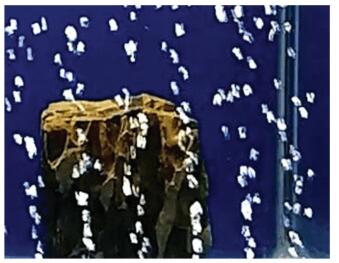
With the development and utilization of marine resources, underwater robots for exploration and operation are becoming increasingly important. Therefore, it is necessary to develop more advanced underwater robot vision technologies to accurately locate and track underwater targets, among which the clarity of underwater images is crucial. When ships, torpedoes, and propellers move at a high speed, a large number of bubbles are generated due to the cavitation effect, causing the target to be blocked and the information to be seriously lost, as shown in Fig. 1. In the underwater welding operation, the high temperature of the welding point vaporizes the water to generate bubbles, and the seam information is blocked, which seriously interferes with the positioning of the weld seam and the welding path planning. Therefore, the image enhancement processing and elimination of the bubble field in the underwater image are pressing problems to be solved. The underwater image bubble noise removal method proposed in this paper can be applied to many fields such as underwater military reconnaissance, resource detection, fish pond inspection, and underwater operation.

|
Fig.1 Underwater bubble noise |
At present, removing bubble noise in underwater images mainly involves spatial method and temporal method. Kong[1] used the independent component analysis (ICA) algorithm to separate the background from the moving object and remove the bubbles for underwater reconnaissance, so as to weaken the bubble field in the image. However, this method is only suitable for background static conditions. When the background moves, the bubble removal effect is poor. Xu[2] proposed to use clustering algorithm to remove the bubble noise in the image for underwater welding, but its threshold needs to be set manually, as it does not take into account the situation that the number of bubbles is large and continuous. Zielinski[3] proposed a method based on the optical flow method for ocean bubble detection. Experiments were conducted on a single bubble detection without considering the overlapping of bubbles. Yamashita[4] used the gray-scale probability distribution of pixels in continuous video frame images to create an image background and remove the bubble interference through the background difference method. Although this method can reduce the interference caused by the background change by continuously updating the background image, the problem of bubble removal in the case of background motion due to camera shake cannot be solved.
Some researchers also studied the removal of other image noise interferences such as snowflakes and raindrops. Hase[5] proposed a method to remove snowfall noise from video while eliminating the influence of pedestrians and other moving objects. Garg[6] analyzed the effect of rainfall on camera imaging. He established a related mathematical model, and proposed an algorithm for detecting and removing rainfall in video. Yamashita[7] proposed a method to remove the water droplet interference on the protective glass by the stereo camera. The two images taken at different positions were compared and synthesized to remove the water drop blocking area. However, due to the phenomenon of deformation, decomposition, and merging of bubbles during ascent, the outline of bubbles is uncertain, and there is movement in the background. The above methods are not applicable to the removal of bubble noise.
In the above studies, the effect of background motion on noise removal in images is not considered. The method in this paper compensates for the lack of consideration of the background motion of the image in other methods, and guarantees a good bubble noise removal rate when the camera shakes or the background changes.
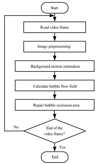
2 Overview of the MethodIn this section, we briefly introduce our method. Overview of the bubble noise removal method is shown in Fig. 2.

|
Fig.2 Outline of the proposed method |
We can see that this method consists of several consecutive steps:
1) Read video frame images. Since the optical flow algorithm is particularly sensitive to background noise, it is necessary to filter the image first;
2) Use LK optical flow algorithm to calculate the background optical flow field, remove the influence of moving targets such as air bubbles, and get the estimated value of background motion;
3) Use HS optical flow algorithm to calculate the bubble optical flow field, and get the area where bubble exists;
4) For the areas that are obscured by bubbles, patching is accomplished by replacing the pixel grayscale values with adjacent frame images.
We repeated the above steps until all the video frames were processed. Finally, we obtained the result of removing the bubble noise.
3 Background Motion EstimationIn this section, we used the LK (Lucas-Kanade) optical flow algorithm to calculate the motion estimation of the background.
3.1 Optical Flow AlgorithmOptical flow is the instantaneous velocity of pixel motion of a moving object in the observation plane. The optical flow field is obtained by arranging the velocity vectors spatially.
The optical flow algorithm assumes that the instantaneous grayscale value does not change. Assume that at time t, the gray value at pixel (x, y) is E(x, y, t) and the speed is V=(u, v). As time goes on, after a period of time Δt, the following formula is established:
| $ E(x, y, t)=E(x+Δx, y+Δy, t+Δt) $ | (1) |
After the derivation, the optical flow constraint equation is:
| $ \frac{{\partial E}}{{\partial x}}u + \frac{{\partial E}}{{\partial y}}v + \frac{{\partial E}}{{\partial t}} = 0 $ | (2) |
Due to the aperture problem, the actual optical flow satisfying the constraint equation can only determine the component of the optical flow in the gradient direction, but it cannot determine its component in the vertical direction of the gradient, so additional constraints need to be added.Horn and Schunck[8] proposed a global smoothing constraint algorithm based on optical flow which uses the global energy function and minimizes it to obtain the optical flow field. Lucas and Kanade[9] proposed a calculation method that assumes that the optical flow is a constant in the neighborhood of the pixel, and then used a least-squares method to solve the basic optical flow equation for all pixels in the neighborhood.
The LK algorithm is a sparse optical flow method that is insensitive to noise and cannot provide optical flow information within the uniform region of the image. The HS algorithm is a dense optical flow method that calculates the optical flow at each pixel, but the amount of calculation is large. In this paper, we used LK optical flow method to calculate the motion of the background, and used HS optical flow method to capture the moving bubbles.
3.2 Background Motion EstimationBackground motion estimation consists of several consecutive sub-steps, including feature point selection, optical flow field calculation, and interference optical flow removal. In this section, we show the details of our method.
3.2.1 Feature Point SelectionThe calculation of the LK optical flow method is based on gradient, and the corner point has gradation change in at least two directions[10], so it is the best feature point of the LK optical flow method.
Commonly used corner point extraction algorithms include Susan, Harris, and Shi-Tomasi[11]. The Shi-Tomasi algorithm is an improvement of the Harris algorithm. In many cases it can get better results than the Harris algorithm. Therefore, in this paper, we used the Shi-Tomasi algorithm to extract feature corners, as shown in Fig. 3(a).

|
Fig.3 Background optical flow field calculation process |
3.2.2 Optical Flow Field Calculation
After obtaining the feature points, the LK optical flow algorithm was used to calculate the optical flow of the feature points. Since the feature points include backgrounds, moving objects, and mismatched points, the calculated result was mixed with these three optical flows, as shown in Fig. 3(b). We must remove the interference between moving objects and mismatched points to get the background motion.
3.2.3 Interference Optical Flow RemovalFrom the image, we can see that the background area occupies a large proportion, so the number of feature points in the background is more than that of bubbles and other moving objects. Therefore, according to the optical flow of the corner point, the motion of the moving object and other external points can be removed and the background motion can be estimated.
We assumed that the optical flow vector obeys a two-dimensional Gaussian distribution. The elimination of non-background feature data points in the optical flow vector was performed in two steps.
1) Firstly, we analyzed the direction angle of the optical flow vector. We calculated the mean and variance of the orientation angle θ and used the Layda criterion to remove data with large angular standard deviation. If there are n optical flow vectors, the direction angle mean θ and variance σθ are:
| $ \begin{array}{l} \;\;\;\;\;\;\;\;\;\;\bar \theta = \frac{1}{n}\mathop \sum \limits_{i = 0}^n {\theta _i}, \\ {\sigma _\theta } = \sqrt {\frac{{\mathop \sum \limits_{i = 0}^n {{\left( {{\theta _i} - \bar \theta } \right)}^2}}}{n}} \end{array} $ | (3) |
If the direction angle θi is within (θ±3σθ), it is retained, otherwise, it is removed.
2) Then, we further analyzed the modulus of optical flow vector. We calculated the mean p and variance σp of the remaining m vector modulus,
| $ \bar p = \frac{1}{m}\mathop \sum \limits_{i = 0}^m {p_i}, {\sigma _p} = \sqrt {\frac{{\mathop \sum \limits_{i = 0}^m {{({p_i} - \bar p)}^2}}}{m}} $ | (4) |
Similar to the first step, we used the Layda criterion to remove data with large modulus standard deviation. If the vector modulus pi is within (p±3σp), it is retained, otherwise, it is removed.
For the processed optical flow vectors, the mean pe of the modulus and the mean θe of the angle were calculated as the motion estimation of the background,
| $ {{\bar p}_e} = \frac{1}{k}\mathop \sum \limits_{i = 0}^k {p_i}, {{\bar \theta }_e} = \frac{1}{k}\mathop \sum \limits_{i = 0}^k {\theta _i} $ | (5) |
Therefore, the background motion homogeneous transformation matrix M is:
| $ \mathit{\boldsymbol{M}} = \left[ {\begin{array}{*{20}{c}} 1&0&{{{\bar p}_e} \cdot \cos ({{\bar \theta }_e})}\\ 0&1&{{{\bar p}_e} \cdot \sin ({{\bar \theta }_e})}\\ 0&0&1 \end{array}} \right] $ | (6) |
In the previous section, we obtained the background motion vector due to camera instability. In this section, we further detected the bubble area and repaired the missing pixels due to the occlusion of the bubble.
4.1 Bubble Area DetectionThe background motion estimation was used as the initial value of the HS dense optical flow algorithm for iterative operations. Because the same initial value was used for the entire image, the problem that the optical flow cannot be calculated by the LK optical flow algorithm in the image smooth region was solved. By using this method, the bubbles can be separated from the background with less iterations, thus speeding up the calculation.
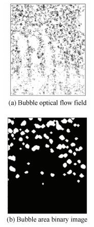
We compared the calculation result of HS algorithm with the background motion estimation vector, and used the mean and standard deviation of previously calculated background motion vector's direction angles and modulus to determine whether each pixel is a background point. If the direction angle is in the range (θe±3σθ) and the mode is in the range (pe±3σp), it is the background point, otherwise, it is the bubble point. Binarizing the obtained results, we can get:
| $ E\left( {x, y} \right) = \left\{ \begin{array}{l} 255, \theta \in \left[ {{{\bar \theta }_e} - - 3{\sigma _\theta }, {{\bar \theta }_e} - + 3{\sigma _\theta }} \right], \\ \;\;\;\;\;\;p \in \left[ {{{\bar p}_e} - 3{\sigma _p}, {{\bar p}_e} + 3{\sigma _p}} \right]\\ 0, \;\;\;\;{\rm{Others}} \end{array} \right. $ | (7) |
Then, we further morphologically filtered, dilated, and eroded the binary image to obtain the bubble region, as shown in Fig. 4(b).

|
Fig.4 Bubble area extraction |
4.2 Occlusion Area Repair
In order to obtain a clearer background image, it is necessary to repair the area occluded by bubbles in the image.For the pixels that are occluded by bubbles in the current frame, they can be repaired by adjacent frames.
Assume that in the frame n, (xn, yn) is a pixel in the occluded area. In the images m frames away from it, the corresponding pixels are (xn-m, yn-m) and (xn+m, yn+m). Considering that there is motion in the background, we aligned the front and rear frame images with the current frame. According to the background motion matrix M obtained in the previous section, we got the transformation between homogeneous coordinates as:
| $ \left\{ \begin{array}{l} {({x^{n - m}}, {y^{n - m}}, 1)^{\rm{T}}} = \mathit{\boldsymbol{M}}_{n - m}^{{n^{\rm{T}}}}{({x^n}, {y^n}, 1)^{\rm{T}}}\\ {({x^{n + m}}, {y^{n + m}}, 1)^{\rm{T}}} = \mathit{\boldsymbol{M}}_n^{n + m}{({x^n}, {y^n}, 1)^{\rm{T}}} \end{array} \right. $ | (8) |
Since there are many frames as repair reference, the priority calculation is introduced here, and the information in the image frame with a high priority was preferentially used for repair. Assuming that the occluded area in the image frame n is An, the annular area after expanding outward by w pixels is Rn.The corresponding annular area in the adjacent frame image is Rn+m. We calculated the average of the grayscale differences of all pixels in the Rn and Rn+m regions to determine the priority.
Assuming that the m+n frame has the highest priority, the pixel corresponding to An was searched in the frame, and the gray value was directly copied to repair An. If the pixel is unknown, it is searched in the next highest priority frame until all pixels in An are repaired.
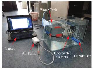
5 Experimental Results and AnalysisIn order to verify the removal effect of image bubble noise, we built an underwater bubble image acquisition experiment device, as shown in Fig. 5. We produced continuous bubbles with air pump, and used underwater camera to take 60fps video. The underwater camera has 2.1 Megapixel, and supports for taking 1080P HD video.

|
Fig.5 Experimental setup |
Three frames from the original video are shown in Fig. 6(a). The images contained a lot of bubble noise, which caused some occlusion to the background. At the same time, we found that the background was in motion. The results of removing the bubble noise is shown in Fig. 6(b). Most of the bubble noise was removed, but the removal rate was low at the location where the bubbles were formed, because the bubbles size were small. The difference between the original and the de-bubble noise frames are shown in Fig. 6(c). The main difference was the bubble area, and the background information was well preserved. We processed the same video with the ICA algorithm and got the de-bubble noise frames as shown in Fig. 6(d).Compared with our method, the ICA algorithm can remove some bubble noise when processing the video with background motion, but the background information becomes more blurred.This is because there is no background motion compensation in the ICA algorithm, resulting in many background pixels being misidentified as moving targets.The experiment shows that our method can effectively remove bubble noise in underwater images.

|
Fig.6 Bubble removal experiment results |
6 Conclusion
In this paper, we proposed a method to remove the bubble noise in the image. We used the optical flow method to detect the motion of the bubble, and used the adjacent frame image to complete the repair of the bubble occlusion area. This method takes into account the background motion caused by the instability of the camera and can compensate for the lack of background translation motion. The experimental results of image processing show that this method is feasible. At present, our method does not consider the rotation and scaling of the image, but we hope to solve these problems in future research work.
| [1] |
Kong X W, Yang J H, Zhou B, et al. Underwater images enhancement method based on motion field separation. Journal of Changchun University of Science & Technology, 2014, 37(1): 61-64. DOI:10.3969/j.issn.1672-9870.2014.01.017 (  0) 0) |
| [2] |
Xu P F, Zhang H, Jia J P, et al. Analyses on interference factors on image in underwater welding robot vision sensor system. Welding & Joining, 2008(5): 33-37. DOI:10.3969/j.issn.1001-1382.2008.05.008 (  0) 0) |
| [3] |
Zielinski O, Saworski B, Schulz J. Marine bubble detection using optical-flow techniques. Journal of the European Optical Society Rapid Publications, 2010, 5(5): 16-21. DOI:10.2971/jeos.2010.10016s (  0) 0) |
| [4] |
Yamashita A, Kato S, Kaneko T. Robust sensing against bubble noises in aquatic environments with a stereo vision system. IEEE International Conference on Robotics and Automation. Piscataway: IEEE, 2006, 928-933. DOI:10.1109/robot.2006.1641828 (  0) 0) |
| [5] |
Hase H, Miyake K, Yoneda M. Real-time snowfall noise elimination. Proceedings 1999 International Conference on Image Processing. Piscataway: IEEE, 1999, 2(2): 406-409. DOI:10.1109/icip.1999.822927 (  0) 0) |
| [6] |
Garg K, Nayar S K. Detection and removal of rain from videos. Proceedings of the 2004 IEEE Computer Society Conference on Computer Vision and Pattern Recognition, 2004. CVPR 2004. Piscataway: IEEE, 2004. 1-8. DOI: 10.1109/cvpr.2004.1315077.
(  0) 0) |
| [7] |
Yamashita A, Tanaka Y, Kaneko T. Removal of adherent waterdrops from images acquired with stereo camera. 2005 IEEE/RSJ International Conference on Intelligent Robots and Systems. Piscataway: IEEE, 2006, 89(1): 2021-2027. DOI: 10.1109/iros.2005.1545103.
(  0) 0) |
| [8] |
Horn B K, Schunck B G. Determining optical flow. Artificial Intelligence, 1981, 281(81): 185-203. (  0) 0) |
| [9] |
Lucas B D, Kanade T. An iterative image registration technique with an application to stereo vision. Proceedings of the 7th International Joint Conference on Artificial Intelligence. San Francisco CA: Morgan Kaufmann Publishers Inc., 1981, 2: 674-679.
(  0) 0) |
| [10] |
Chu J, Shi M, Fu X. Detection of moving target in dynamic background based on optical flow. Journal of Nanchang Hangkong University (Natural Sciences), 2011, 25(3): 1-6. DOI:10.3969/j.issn.1001-4926.2011.03.001 (  0) 0) |
| [11] |
Zhu J, Ren M W, Yang Z J, et al. Fast matching algorithm based on corner detection. Journal of Nanjing University of Science & Technology, 2011, 35(6): 755-758. DOI:10.3969/j.issn.1005-9830.2011.06.005 (  0) 0) |
 2019, Vol. 26


