2. The Engineering & Training Center, Inner Mongolia University of Science and Technology, Baotou 014010, Inner Mongolia, China
Linear rolling guide feed unit and worktable have been gradually replaced the traditional sliding linear guide (except heavy machine tool), and ball linear guide workplace is a key component of CNC machining tools[1]. Precision retaining ability of the linear guide feed unit mainly depends on positioning accuracy and stiffness degeneration because of the friction and wear in the process of running. With the development of 0.1 μ m CNC machine tools and special high precision machine tools, there is a strict requirement for the performance of the linear guide workplace. Therefore, it is of great significance to study the mechanical characteristics of the BLGFU. Yong-sub Y[2] studied comprehensively the dynamic characteristics of linear rolling rail system. In Ref.[3], a commercial guideway system is texted, and the nonlinear parameters of the guideway system are identified. By using Hertz contact theory, Jiang and Zhu[4] calculated the linear rigidity of linear rolling guide, with ball screw pair of machine tool dynamic characteristics of the integration of a linear guide of theory model. Theory model of machine tool dynamic characteristics of the integration of a linear guide with ball screw was established. Their research focuses on the influence law of the work load for the integration of the dynamic stiffness. Liu[5] established the stiffness model of linear rolling guide under several loads in the situation of LMGs. Zhong[6] analyzes the relationship of stress between roller and rail. Through the theoretical mechanics and related knowledge, the horizontal and vertical stiffness model of guide and three directions stiffness model was built based on Palmgren formula. Based on test characteristic parameters of surface per unit area, Rahmani and Bleicher[7] made some analysis and experimental research on the static rigidity of the linear guide guideway, by using Hertz theory of contact. Then, based on the experimental data, they analyzed the static rigidity of the linear guideway on three orthogonal axes. Under the experimental conditions of external force 10 kN and three preload grades, the influence of velocity on rigidity is obtained by comparing experimental data.
Shimizu[8] did several experiments on the four-slider working table to analyze and verify the influence of the stiffness of the sliders in the linear rolling guide on the kinematic and positioning accuracies of whole working table. Wang[9] through the T.L.Horng's deformation computation theory, calculated out the biggest deformation of the linear roller guide rail pair under rated load, and the results verified the correctness of theory calculation through the study of the finite element contact analysis of contact region. Zou, Wang[10] analyzed the initial and failure contact stiffness of guide, and verified the relationship between contact stiffness and temperature through several experiments. They concluded that the stiffness degradation can be separated into two stages which are abrasion and temperature deformation.
The research of linear guide pair of numerical control machine tool mainly includes the following points: first, the staticrigidity and dynamic stiffness of the rolling guide pair; secondly, the vibration produced by the machine tool operation; thirdly, the friction characteristic of the rolling guide rail. Based on the Hertz theory, Wu et al.[11-12] calculated and analyzed the linear stiffness between ball and rail. Eschmann, and Hasbargen[13] studied the factors that affect the stiffness of the rolling guide pair. The analytical studies were conducted using Hertz theory. Then, they carried out some experiments to investigate the static rigidity of industrial ball bearing linear guides in normal, lateral and angular directions. Under three preload levels, the maximum force of 10 KN has been applied to measure it. The results of analytical and experimental investigations had been compared. Then, the guide was driven with different velocities to find the influence of movement on the rigidity. Jui Pin Hung[14] established the finite element model of the rolling rail under different loads based on the Hertz contact theory. Furthermore, they studied the influence of external load on the contact stiffness and modified the finite element model based on test results. Zheng[15] pointed out that the precision of the guide rail, the factors affecting the accuracy of the guide rail, straightness measurement methods and evaluation methods, but did not study the reasons for the accuracy degradation. In addition to the above, Zhang[16] analyzed the feed device of the elliptical roller linear guide, and obtained the relationship between the angle errors or linear errors of the worktable on three orthogonal axes and the external force acting point.
In addition to the above research results, based on the characteristic parameters of test dates, Pawełko P and Berczyński S[17] presented the methodological basis and methods of modeling roller guides. This modeling consist of a carriage and profiled guide rail with introduced preload. Based on the Palmgren Equation[18-19], the stiffness model in the horizontal and vertical direction is established. Mahdi Rahmani, Friedrich B Leicher[20] concerned with experimental investigations on static stiffness of linear motion guides, and carried out some experiments to investigate the static stiffness in normal, lateral and angular directions. Then they measured three different angular deflections in roll, pitch and yaw directions. Jiang and Li[21] provided a new model for calculating the deformation between a rolling body and its raceway. This model is used to calculate contact deformation and is verified by tests and provides a reference for the equipment.
All these researches have revealed many useful findings. However, very few people consider the influence of contact angle changes on the stiffness of the BLGFU. When the force point acting on the worktable is changed, few people pay attention to the influence of the contact angle change on the angle errors and linear errors of the BLGFU. The effect of the change of the contact angle on the contact rigidity was not considered in the previous studies. The linear guide pair and the ball screw pair are important bearing parts of the machine tool, and the contact angle has little influence on the stiffness of the ball screw pair, but the contact angle may have a great influence on the stiffness of the linear guide pair, therefore contact angle has a great influence on the accuracy of the BLGFU. In this paper, a model of the contact stiffness considering the variety of the contact angle is established. Based on this model, the change trend of the contact deformation and the motion accuracy degradation of the BLGFU are analyzed. Furthermore, the five errors of the linear feed unit and the relationship between the external forces are obtained. Finally, through an experiment on the test system of the BLGFU, the horizontal contact stiffness and vertical stiffness can be achieved, and then proof indirectly the correctness of the model accuracy degradation. By comparison the model simulation and the experimental data, verifying the rationality of the model established owing to the simulation dates and experimental dates are in good consistency.
2 Model of Stiffness and Accuracy of Linear Guide Feed Unit 2.1 Establishment of Coordinate System and Load Analysis of GuideThe ball linear guide feed unit is consist of two ball linear guideways and four sliders, and each of which has a series of balls. When the slider slides on the guide rail, assume that the adjacent balls in one column do not contact each other. When the slider is subjected to an external load, in the preload range, all the balls in a column are assumed to bear the same load. Two linear errors and three angle errors produced by load of the workable can be expressed as δy, δz, εx, εy, εz. Among them, δy and δz are the straightness accuracy errors in Y and Z directions. εx, εy and εz are respectively the rotational errors around three axes.
As shown in Fig. 1, the coordinate system O0 (0, 0, 0) in the center of the feed unit is set up. Then, after the slider is loaded, the coordinate system O1(0, δy, δz) is established[16].

|
Fig.1 Coordinate system and errors of linear guide pair |
According to the theory of the multi-body system, the coordinate transformation matrix of O0 to O1 coordinates 0T1 is expressed as[22]:
| $ ^0{\mathit{\boldsymbol{T}}_1} = \left[ {\begin{array}{*{20}{c}} 1&{ - {\varepsilon _z}}&{{\varepsilon _y}}&0\\ {{\varepsilon _z}}&1&{ - {\varepsilon _x}}&{{\delta _y}}\\ { - {\varepsilon _y}}&{{\varepsilon _x}}&1&{{\delta _z}}\\ 0&0&0&1 \end{array}} \right] $ | (1) |
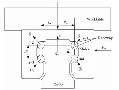
When the sliderbears force from the worktable, the stress distribution and deformation in the contact region between the ball and rail are generated. Qi is the normal contact force loaded on the ball. F1y and F1z are the normal external force loaded on the guide 1 in y direction and z direction respectively. The relative position and the force exerted on every column ball are shown in Fig. 2.
|
Fig.2 Force analysis of slide 1 |
In Fig. 2, Ly is the distance between the center of ball in the 1th (3th) row and the 2th (4th) in Y direction. Lz is the distance between the center ball in the 1th (2th) row and the 4th (3th) in Z direction.
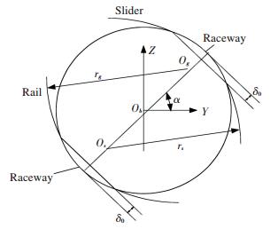
As shown in Fig. 3, without the external load, the distance from the curvature center of the slider raceway to that of the guide raceway is defined as OsOg. In Fig. 3, Os is the curvature center of the slider rail, and Og is the curvature center of the guide rail. The ball is clamped between the slider raceway and the guide rail raceway. The distance between the center of curvature of the slider rail and that of the guide is obtained when the slider is not bearded to external force. This distance is given by the formula (2):
|
Fig.3 Deformation and curvature relationship of rolling body and linear raceway |
| $ {O_s}{O_g} = {r_s} + {r_g} - {D_w} = \left( {2f - 1} \right){D_w} $ | (2) |
where r=fDw, Dw is the diameter of the ball, f is the curvature ratio. The slider and the guide are viewed as a rigidity body, and the deformation of the ball is analyzed.
By the conversion of the coordinate system, the curvature center coordinates of the slider can be expressed as:
| $ \left[ {\begin{array}{*{20}{c}} {{x_{ij(0)}}}\\ {{y_{ij(0)}}}\\ {{z_{ij(0)}}}\\ 1 \end{array}} \right]{ = ^0}{\mathit{\boldsymbol{T}}_1}\left[ {\begin{array}{*{20}{c}} {{x_{ij(1)}}}\\ {{y_{ij(1)}}}\\ {{z_{ij(1)}}}\\ 1 \end{array}} \right] $ | (3) |
Meanwhile, the coordinates of the curvature center of the rail of slider can be expressed as[16]:
| $ \left\{ \begin{array}{l} x{'_{ij(0)}} = {x_{ij(1)}} - {\varepsilon _x}{y_{ij(1)}} + {\varepsilon _y}{z_{ij(1)}}\\ y{'_{ij(0)}} = {\varepsilon _z}{x_{ij(1)}} + {y_{ij(1)}} - {\varepsilon _x}{z_{ij(1)}} + {\delta _y}\\ z{'_{ij(0)}} = - {\varepsilon _y}{z_{ij(1)}} + {\varepsilon _x}{y_{ij(1)}} + {z_{ij(1)}} + {\delta _z} \end{array} \right. $ | (4) |
When the slider bears the force from the worktable, due to force, the ball is deformed, so that the center of curvature of both sides of the ball will change. When the value of the external force or the point of action is changes, the contact angle of each ball in the four sliders is different. Therefore, the variation of each ball must be considered. Assume that Os'Og' represents the distance of the curvature center of the slider rail and the guide rail of the j-th ball in the i-th column.
| $ {O^{'}}_s{O^{'}}_g = {[|{y_{ij(0)}} - y{'_{ij(0)}}|]^2} + {[|{z_{ij(0)}} - z{'_{ij(0)}}|]^2} $ | (5) |
where, Os' is the curvature center after elastic deformation occurs on the raceway surface of slider, and Og' is the curvature center after elastic deformation occurs on the raceway surface of guide.
2.2 Deformation Analysis Between Ball and RacewayThe increase in ball diameter leads to the elimination of the gap and improvement of the stiffness of guide, as well as slight deformation between rolling balls and roller path, where the force causing the deformation is called as the initial preload of guide.Since the material properties of the slider raceway and the rail raceway are the same, the bilateral pressure of the ball is the same when the ball is subjected to normal pressure. Assume that the initial deformation of single ball is δ0, and the initial preload in single row is Q0. Then Eq.(6) can be found as follows, Hertz contact condition of ball and rail as shown in Fig 3:
| $ {\delta _0} = {K_a} \cdot Q_0^{2/3} $ | (6) |
In order to improve the contact stiffness of the rolling linear guide pair, the clearance between the roller and raceway must be eliminated. Usually, each column roller body of the linear rolling guide was applied a preload Q0. The initial deformation of the center of the rolling relative guide raceway produced by the preload is δ0. δij is deformation of single ball in normal direction between ball and raceway. The elastic deformation of each ball is[16]:
| $ {\delta _{ij}} = \frac{{{O'}_s{O'}_g - {O_s}{O_g}}}{2} + {\delta _0} $ | (7) |
Base on hertz theory, the model of contact force and elastic deformation of the ball are defined as follows[23]:
| $ \delta = 1.5 \times \frac{{2K}}{{{\rm{ \mathsf{ π} }} \cdot \mu }}{\left[ {\frac{{{{\left( {1 - {\nu ^2}} \right)}^2}}}{{{E^2}}} \cdot \frac{{\sum \rho }}{3} \cdot {Q^2}} \right]^{1/3}} $ | (8) |
where, E is the elasticity modulus of rail materials, and the material of the rail is the same as that of the ball. δ is the amount of contact deformation between ball and rail, and Q is the normal contact force loaded on the ball. ν is the Poisson ratios of ball and roller path materials, respectively.∑ρ=ρ11+ρ12+ρ21+ρ22 is the sum of curvatures where ρ11, ρ12 are the principal curvatures of balls' contact points on the two orthogonal principle planes while ρ21, ρ22 are the principal curvatures of roller path's contact points on the two orthogonal principle planes, respectively.
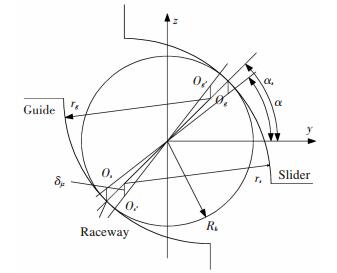
2.3 Analysis of Contact Angle of BallsThe coordinate system Ob is set up in the center of ball, which is shown in Fig. 4.
|
Fig.4 The contact angle changes of upper row of ball |
Before applying the stress, the contact angles are α while they change to αs after the stress the contact angles. Furthermore, before the deformation, the curvature centers of roller paths in the guide and slider are Os and Og respectively while they changed to Os' and Og' after the deformation. The vertical deformation of single ball is δz. rs is the curvature radius of rail of slider and rg is the curvature radius of rail of guide, respectively. fs and fg are the curvature ratios between the roller paths of slider and ball, the roller paths of slider and guide, respectively. Rb is the radius of ball. Using the Hertz theory, the contact angle variation of lower row of ball under external force can be achieved. The following equations can be derived from the geometrical relationship shown in Fig. 4:
| $ \overline {{O'}_s{O'}_g} = {\left[ {{{(\overline {{O_S}{O_g}} \sin \alpha + {\delta _{jz}})}^2} + {{(\overline {{O_S}{O_g}} \cos \alpha )}^2}} \right]^{0.5}} $ | (9) |
| $ \sin {\alpha _{sij}} = \frac{{\overline {{O_S}{O_g}} \sin \alpha + {\delta _{zj}}}}{{\overline {{O'}_s{O'}_g} }} $ | (10) |
where δzj is deformation of single ball in vertical direction. Before applying the stress, the contact angles is α while they change to αsij after the stress the contact angles.
| $ \left\{ \begin{array}{l} {F_{1z}} = \sin {\alpha _{sij}}\left[ {\mathop \sum \limits_{j = 1}^n \left( {{Q_{1j}} + {Q_{2j}}} \right) - \mathop \sum \limits_{j = 1}^n \left( {{Q_{3j}} + {Q_{4j}}} \right)} \right]\\ {F_{1y}} = \cos {\alpha _{sij}}\left[ {\mathop \sum \limits_{j = 1}^n \left( {{Q_{1j}} + {Q_{2j}}} \right) - \mathop \sum \limits_{j = 1}^n \left( {{Q_{3j}} + {Q_{4j}}} \right)} \right] \end{array} \right. $ | (11) |
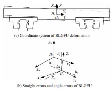
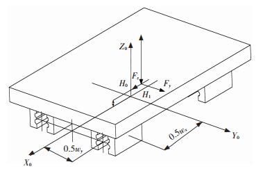
The coordinate system H0 in the geometry center of the linear guide feed unite is established, when the linear guide feed unite is no bearing extra force. The X0 axes is parallel with the movement direction of linear guide feed unite, and the Y0 axes and Z0 axes are parallel with horizontal direction and vertical direction of linear guide feed unite, respectively. The coordinate system H1(0, ΔY, ΔZ) is set up in the center of the linear guide feed unite, while the feed unite is bearing extra force and the deformation occurring, The coordinate system H0 and H1 are shown in Fig. 5.
|
Fig.5 Coordinate system and errors of BLGFU bearing load |
As shown in Fig. 5, the BLGFU is composed of two linear rolling guide pairs and one worktable. Each of the linear rolling guide pairs consists of four rows of balls and two sliders. The BLGFU will have deformations when the worktable bearing the force acting on the spindle tool of the machine tool. Assume that the dotted line represents the BLGFU after loading, and the black graphic represents the BLGFU before loading. The coordinate system H0 (0, 0, 0) in the geometry center of the worktable is set up. Then, after the worktable is loaded, the coordinate system H1(0, Δy, Δz) is established.
Similarly, the coordinate transformation matrix of H0 to H1 coordinates 1T2 is expressed as:
| $ ^1{\mathit{\boldsymbol{T}}_2} = \left[ {\begin{array}{*{20}{c}} 1&{ - {E_Z}}&{{\Delta _Y}}&0\\ {{E_Z}}&1&{ - {E_X}}&{{\Delta _Y}}\\ { - {E_Y}}&{{E_X}}&1&{{\Delta _Z}}\\ 0&0&0&1 \end{array}} \right] $ | (12) |
By the conversion of the coordinate system, the curvature center coordinates of feed unit can be expressed as:
| $ \left[ {\begin{array}{*{20}{c}} {{X_{(0)}}}\\ {{Y_{(0)}}}\\ {{Z_{(0)}}}\\ 1 \end{array}} \right]{ = ^1}{\mathit{\boldsymbol{T}}_2}\left[ {\begin{array}{*{20}{c}} {{X_{(1)}}}\\ {{Y_{(1)}}}\\ {{Z_{(1)}}}\\ 1 \end{array}} \right] $ | (13) |
In the coordinate system, with the external load, the symmetric center of the linear guide feed unit is defined as (X(1), Y(1), Z(1)):
| $ {X_{(1)}} = \left\{ \begin{array}{l} {W_x} - \frac{1}{2}n \cdot {D_w} + {D_w} \cdot j, \;\;\;m = 1, 2\\ - {W_x} + \frac{1}{2}n \cdot {D_w} - {D_w} \cdot j, m = 3, 4 \end{array} \right. $ | (14.1) |
| $ {Y_{(1)}} = \left\{ \begin{array}{l} {W_y} + {L_y} - \left( {f - \frac{1}{2}} \right)\cos {\alpha _S}, m = 1, 2\\ {W_y} - {L_y} + \left( {f - \frac{1}{2}} \right)\cos {\alpha _S}, m = 3, 4 \end{array} \right. $ | (14.2) |
| $ {Z_{(1)}} = \left\{ \begin{array}{l} {L_z} - \left( {f - \frac{1}{2}} \right)\sin {\alpha _S}, \;\;\;\;\;m = 1, 4\\ - {L_z} + \left( {f - \frac{1}{2}} \right)\sin {\alpha _S}, \;\;\;m = 2, 3 \end{array} \right. $ | (14.3) |
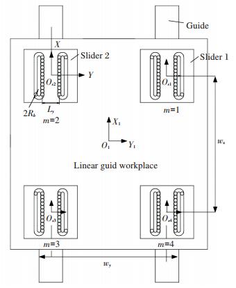
where m is the number of slider. Wy is the distance between the center points of slider in Y direction. Wz is the distance between the geometry centers of adjacent slider in Z direction, as shown in Fig. 6.
|
Fig.6 Structure and geometry of BLGFU |
As shown in Fig. 7, each deformation of the ball has two components in the horizontal and vertical direction, the deformation of which is expressed as:

|
Fig.7 Deformation analysis of feed unit |
| $ \left\{ \begin{array}{l} {\delta _{zj}} = {\delta _j}\sin {\alpha _{sij}}\\ {\delta _{yj}} = {\delta _j}\cos {\alpha _{sij}} \end{array} \right. $ | (15) |
Along with an external load, m is the number of slider. δzm is average deformation of all balls in m-th guide in vertical direction. The new contact angle of the feed unit is expressed as:
| $ {\alpha _{YS}} = \arctan \frac{{\left| {\frac{1}{2}\mathop \sum \limits_{m = 1}^4 {\delta _{zm}}} \right|}}{{\left| {{W_x}} \right|}} $ | (16) |
| $ {\alpha _{XS}} = \arctan \frac{{\left| {\frac{1}{2}\mathop \sum \limits_{m = 1}^4 {\delta _{zm}}} \right|}}{{\left| {{W_y}} \right|}} $ | (17) |
where, m is the number of slider, and αXS is the angle of feed unit around X axis in vertical direction. αYS is the angle of feed unit around Y axis in vertical direction. δzm=1/j(δz1+δz2+…δzj).
By the conversion of the coordinate system, the curvature center coordinates of the feed unit can be expressed as:
| $ \left\{ \begin{array}{l} {X'}_{(0)} = {X_{(1)}} - {E_X}{Y_{(1)}} + {E_Y}{Z_{(1)}}\\ {Y'}_{(0)} = {E_Z}{X_{(1)}} + {Y_{(1)}} - {E_X}{Z_{(1)}} + {\Delta _Y}\\ Z{'_{(0)}} = - {E_Y}{Z_{(1)}} + {E_X}{Y_{(1)}} + {Z_{(1)}} + {\Delta _Z} \end{array} \right. $ | (18) |
The displacement coordination equation of linear feed device is:
| $ \left\{ \begin{array}{l} \frac{{{\delta _{y1}} + {\delta _{y3}}}}{2} = \frac{{{\delta _{y2}} + {\delta _{y4}}}}{2} = {\Delta _y}\\ \frac{{{\delta _{z1}} + {\delta _{z3}}}}{2} = \frac{{{\delta _{z2}} + {\delta _{z4}}}}{2} = {\Delta _z} \end{array} \right. $ | (19) |
In the same way, the force exerted on the other sliders in Y, Z direction are defined as F2y, F3y, F4y, F2z, F3z, F4z.
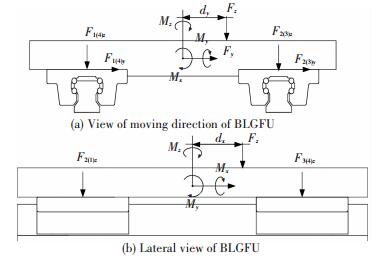
As shown in Fig. 8, it is the complete stress of the linear rolling worktable. Assume that the offset between the bearing point of the force and the geometric center of the worktable is dx in X direction, and that is dy in Y direction. The mechanic balance equations of the BLGFU are expressed as follows:
|
Fig.8 Force analysis of BLGFU |
| $ \left\{ \begin{array}{l} \left( {{F_{1z}} + {F_{2z}} + {F_{3z}} + {F_{4z}}} \right)\sin {\alpha _{mz}} - {F_z} = 0\\ \left( {{F_{1y}} + {F_{2y}} + {F_{3y}} + {F_{4y}}} \right)\cos {\alpha _{mz}} - {F_y} = 0\\ {W_y}\left( {{F_{2z}} + {F_{3z}} - {F_{1z}} - {F_{4z}}} \right)\sin {\alpha _{mz}} + 2{M_x} + {F_z}{d_y} = 0\\ {W_x}\left( {{F_{1z}} + {F_{2z}} - {F_{3z}} - {F_{4z}}} \right)\sin {\alpha _{mz}} + 2{M_y} + {F_z}{d_x} = 0\\ {W_x}\left( {{F_{3y}} + {F_{4y}} - {F_{1y}} - {F_{2y}}} \right)\cos {\alpha _{mz}} + 2{M_z} + {F_y}{d_x} = 0 \end{array} \right. $ | (20) |
where, Mx, My, Mz are the torques around the X axis, Y axis, and Z axis, respectively. As shown in Fig. 9. Wy is the distance between the geometry center of the slider 1 and slider 2. And Wx is the minimum distance between the geometry center of the slider 2 and slider 3.
|
Fig.9 Position of bearing point and coordinate system of BLGFU |
3 Simulation
Based on the established model, a series of simulation can be obtained. The results are shown in Fig. 10-Fig. 15.

|
Fig.10 Vertical deformation analysis of BLGFU |
|
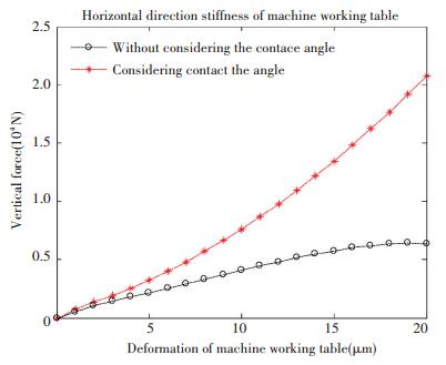
Fig.11 Horizontal deformation analysis of BLGFU |
|
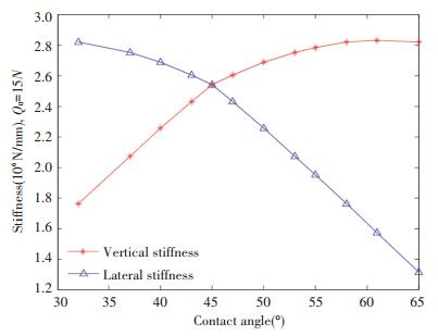
Fig.12 Effect of initial contact angle on X directional stiffness and Y directional |

|
Fig.13 Rotation angle error analysis round X axis of the BLGFU |
|
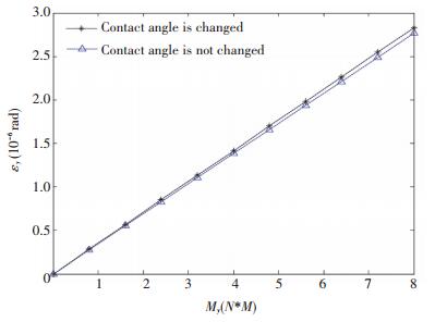
Fig.14 Rotation angle error analysis round Y axis of the BLGFU |
|
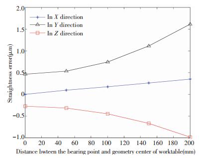
Fig.15 Relationship between the errors and the bearing point of the BLGFU |
From Fig. 10, in the vertical direction, and when the force is equal, we find that, the deformation of the worktable with considering the change of contact angle is bigger than that without considering the change of contact angle. The phenomenon is well explained why the stiffness of the test measurements is always less than the theoretical one. Furthermore, after careful observation of the trend of the star curve in Fig. 10, we find that the tendency of the increase of deformation increases with the increase of the external force. Moreover, the whole curve shows the nonlinear variation.
From Fig. 11, we find that the contact stiffness of the BLGFU in horizontal direction with considering the change of contact angle is bigger than that without considering the change of contact angle. Furthermore, we analyze that the vertical and horizontal deformations are unbalanced after the BLGFU is subjected to a vertical load. With the increase of the external force, the slope of the vertical deformation curve becomes smaller, and the slope of the horizontal deformation curve becomes larger.
The above analysis is the change law of the stiffness under the same initial angle. In addition, the influence of initial contact angle on the stiffness of the BLGFU is analyzed. From Fig. 12, it can be clearly seen that the influence of the initial contact angle on the rigidity of two directions. It can be known from the analysis that the variation in contact angle has an influence on the vertical and lateral (horizontal) stiffness of BLGFU. With the increase of initial contact angle, the trend of the two curves is opposite; the two stiffness values are equal at the contact angle equal 45°. In connection with the actual engineering situation, this paper calculates the change law of the stiffness in two directions of the BLGFU, in the case of contact angles ranging from 30° to 65°.
By applying the model of contact angle variation into the mechanical model of guide, and using the multi-body system theory, as well as considering the initial preload and initial contact angle of every guide, the deformation curve of vertical load can be obtained by solving related equations.
Fig. 13 and Fig. 14 show the effect of external force on the rotation error of the BLGFU in three orthogonal directions.
As shown in Fig. 13 and Fig. 14, due to the variety of the contact angle, and the rotation errors around the X axis and the Y axis are slightly larger. From Fig. 13, the contact angle has a little effect on the three rotational errors. In the direction of movement of the worktable, the angular deformation of the worktable with considering the change of contact angle is bigger than that without considering the change of contact angle. From Fig. 14, in the lateral direction of the worktable, the angular deformation of the worktable with considering the change of contact angle is bigger than that without considering the change of contact angle. The analysis shows that, in the same torque, the angular displacement in the X direction is slightly larger than that in the Y direction. This phenomenon proves the fact that the lateral roll angle rigidity of the BLGFU is smaller than the angular rigidity of its lateral roll.
From Fig. 15, the longer distant between the symmetric center of BLGFU and bearing point, the bigger linear errors all become in varying degrees. The accuracy error of the moving direction (X axis) of the worktable is smaller than that of the lateral direction (Y axis), and the error is smaller than that of the vertical direction (Z axis). The accuracy error in the Y direction is slightly larger than the error in the Z direction. This is due to the structural parameters of the BLGFU. We can know from Fig. 15, with the change of force, the change trend of linear error in Y direction and Z direction shows the nonlinear. The influence of the change of the action point on the linear error of the BLGFU is maximal in the Y direction. Due to the symmetry center table in the origin of coordinates, if the bearing point moves toward the opposite direction illustrated in Fig. 16, the linear errors value remains unchanged, and the direction of the errors is negative.
|
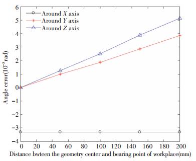
Fig.16 Relationship between the angle error and the bearing point of the BLGFU |
Through computer analysis and calculation, the relationship between the angle error and the bearing point of the BLGFU is shown in Fig. 16, in three orthogonal directions respectively. From Fig. 16, when the distance from the geometry center of the BLGFU to load bearing point is become bigger, three rotational errors all become bigger in varying degrees. The accuracy error around the Y direction is slightly larger than the error in the Z direction. This is due to the structural parameters of the linear guide workplace. When the worktable is bearing to the same external load, the angle error around the X axis is less than that of the Y axis or around the Z axis. As shown in Fig. 8 or Fig. 9, the change law of the errors of worktable is simulated under the condition that the dx remains constant and the dy is increased. Due to the symmetry center table in the origin of coordinates, if the bearing point moves toward the opposite direction illustrated in Fig. 16, the angle error value remains unchanged, and the direction of the errors is negative.
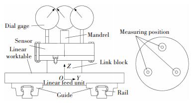
4 ExperimentsIn this paper, the experiments were carried out by applying a high-precision 3-d force transducer to measure the vertical stiffness of the BLGFU under idle loading. The principle of testing apparatus is shown in Fig. 17. The maximum load of gas path system is 20 kN, and the force sensor accuracy is 1 N.
|
Fig.17 Schematic diagram of test measurement |
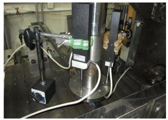
The test system of the BLGFU is shown in Fig. 18. In this paper, the stiffness of each slider is assumed the same. The stiffness of the BLGFU is equivalent to four times of the stiffness of each slider. In order to reduce test errors, the deformation of three points of the worktable are measured through three displacement sensors.
|
Fig.18 Experimental device |
Before the experiment, in order to reduce the installation gap between components, the load was gradually increased to 10 kN, and then unloaded. The loading force is applied to the worktable by a pneumatic path system via an afterburner. The load interval is 50 N, and the average readings of the three sensors are processed after the gas path is pressurized.
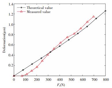
Under the same conditions, the comparison between the experimental measurement data and the theoretical deduction data is shown in Fig. 19 to Fig. 20. Using the previous mathematical model and considering the change of contact angle and initial angle, the theoretical values of the vertical stiffness and the horizontal stiffness are obtained.

|
Fig.19 Vertical deformation curve of experiment and simulation |
|
Fig.20 Horizontal deformation curve of experiment and simulation |
As shown in Fig. 19, the circle line shows the relation between the vertical force and the vertical deformation. The asterisk line represents the theoretical calculation value. In Fig. 20, the red curve shows the relation between the horizontal load and the deformation. The asterisk line represents the theoretical calculation value. The changing regularity of test results is about consistent with the simulation results. When the load is low, the deformation of the BLGFU through experiment is smaller than the simulation result. When the load is high, the deformation of the BLGFU by experiment is bigger than the simulation result.
As shown in Fig. 19 and Fig. 20, it is obvious that the cure of stiffness have the turn point at measured dates. Two obvious turning points appear on the vertical deformation curve of the BLGFU. The vertical stiffness of guide decreases after the first turning point, while increases after the second turning point. The first turning point is caused by a certain gap on the rigid joint surface between the 3-d forces transducer and the rolling guide worktable. Initial deformations of rolling guide worktable show the hysteresis phenomena when the external force is small. There is no turning point on the deformation curve of feed unit under not considering the change of contact angle. In Y direction, there is the second turning point under the conditions of external load of 300 N. In Z direction, there is the second turning point under the conditions of external load of 420 N. The stiffness of linear workplace increases after the second turning point, and still slowly increases when the loading process continues.
By comparing the contact stiffness of the test with the simulation results, there is an error of 18% with the low load and a error of 11% with the high load. The main reason for resulting in the phenomenon is that the contact area between the workbench and the guide exist some clearances. Along with the increase of the load, the clearance is eliminated, and the simulation result is more approaching to the result from the experiment. It is obvious that the model of the contact stiffness has an accuracy and feasibility.
5 Conclusion1) In the vertical direction, with the increase of contact angle, the contact stiffness after considering the change of contact angle is greater than that without considering the contact angle change. But, the contact stiffness in horizontal directions becomes smaller than the contact angle is used as a constant value. The contact angle will change in the vertical loading process, which makes up the deformation to a great extent, this leads to an increase in the stiffness of linear rolling feed unit.
2) Due to the initial contact angle, the linear stiffness in vertical direction is different from the contact stiffness in the horizontal direction. The larger the contact angle, the greater the stiffness in the vertical direction and the smaller the stiffness in the horizontal direction. The accuracy error of the moving direction of the worktable is smaller than that of the lateral direction, and the error is smaller than that of the vertical direction. No matter the vertical direction is horizontal, there is an intersection point between the experimental data curve and the theoretical calculation curve, and the slope of the experimental data curve is larger than the theoretical curve. The reason is that the experimental device is not rigid, but there is a certain gap, which makes always the measured deformation value smaller than the theoretical value.
3) When the distance from the Symmetric center of the BLGFU to load bearing point is become longer, three rotational errors in the three orthogonal directions all become bigger in varying degrees. The accuracy error around the Y direction is slightly larger than the error in the Z direction. We known from analysis on stiffness, when feed unit bearing vertical load, vertical deformation became smaller while horizontal deformation became larger. So change of accuracy error is more sensitively in Y direction than in Z direction.
4) By comparing the contact stiffness of the test with the simulation results, there is an error of 18% with the low load and an error of 11% with the high load. It is obvious that the model of the contact stiffness considering change of contact angle between ball and raceway has an accuracy and feasibility. According simulation and experiment dates, the vertical stiffness bigger than horizontal stiffness of this type feed unite. But, experiment values of stiffness are smaller than simulation values due to the oil film thickness between ball and raceway and gap between link block and linear worktable.
| [1] |
Qu C N, Wu L S, Xiao Y C, et al. Summary of guideway technology research on machine tools. Manufacturing Technology & Machine Tool, 2012(1): 30-36. (  0) 0) |
| [2] |
Yi Y S, Kim Y Y, Choi J S, et al. Dynamic analysis of a linear motion guide having rolling elements for precision positioning devices. Journal of Mechanical Science and Technology, 2008, 22(1): 50-60. DOI:10.1007/S12206-007-1006-9 (  0) 0) |
| [3] |
Dhupia J S, Ulsoy A G, Katz R, et al. Experimental densification of the nonlinear parameters of an industrial translational guide for machine performance evolution. Journal of Vibration & Control, 2008, 14(5): 645-668. DOI:10.1177/1077546307081325 (  0) 0) |
| [4] |
Jiang S Y, Zhu S L. Dynamic characteristic parameters of linear guideway joint with ball screw. Journal of Mechanical Engineering, 2010, 46(1): 92-99. DOI:10.3901/JME.2010.01.092 (  0) 0) |
| [5] |
Liu J S, Zheng S X, Li Z, et al.The rigidity model of linear motion guide in the situation of LMGs standing under several loads.Proceedings of the International Conference on Mechanical Transmissions. Beijing: Chinese Machine Press, 2001.664-666.
(  0) 0) |
| [6] |
Zhong Y, Feng T, Wang Y L. Model for wear prediction of roller linear guides. Wear, 2013, 305: 260-266. DOI:10.1016/j.wear.2013.01.047 (  0) 0) |
| [7] |
Rahmani M, Bleicher F. Experimental and analytical investigations on normal and angular stiffness of linear guides in manufacturing systems. Procedia CIRP, 2016(41): 795-800. DOI:10.1016/j.procir.2015.12.033 (  0) 0) |
| [8] |
Shimizu S. Load distribution and accuracy-rigidity of linear motion ball guides system. Journal of the Japan Society of Precision Engineering, 1990, 56(8): 1445-1451. DOI:10.2493/jjspe.56.1445 (  0) 0) |
| [9] |
Wang W, Wang F J, Zhang X. Contact deformation analysis of the contact region of roller linear guide. Equipment Manufacturing Technology, 2011(1): 4-5. (  0) 0) |
| [10] |
Zou H T, Wang B L. Investigation of the contact stiffness variation of linear rolling guides due to the effects of friction and wear during operation. Tribology Internatinal, 2015, 92: 472-484. DOI:10.1016/j.triboint.2015.07.005 (  0) 0) |
| [11] |
Wu J S S, Chang J C, Hung J P. The effect of contact interface on dynamic characteristics of composite structures. Mathematics and Computers in Simulation, 2007, 74(6): 454-467. DOI:10.1016/j.matcom.2006.07.003 (  0) 0) |
| [12] |
Wu J S S, Chang J C, Tsai G A, et al. The effect of bending loads on the dynamic behaviors of a rolling guide. Journal of Mechanical Science and Technology, 2012, 26(3): 671-680. DOI:10.1007/s12206-011-1228-8 (  0) 0) |
| [13] |
Dai S. Application Handbook of Rolling Bearing of Machine. Beijing: China Machine Press, 1992.
(  0) 0) |
| [14] |
Hung J P. Load effect on the vibration characteristics of a stage with rolling guides. Journal of Mechanical Science and Technology, 2009, 23(1): 89-99. DOI:10.1007/s12206-008-0925-4 (  0) 0) |
| [15] |
Zheng Qianying. High Stiffness of Linear Rolling Guide Design and Precision Analysis. Heilongjiang: Harbin Institute of Technology, 2013(7): 18-23. (  0) 0) |
| [16] |
Zhang W, Wang M, Le B B. Modeling and Simulation on Errors of Feed Unit by Considering Change of Force Bearing Piont. MATEC Web of Conferences, 2017, 104: Article Number: 01012(1-8). DOI: 10.1051/matecconf/201710402012.
(  0) 0) |
| [17] |
Pawełko P, Berczyński S, Grządziel Z. Modeling roller guides with preload. Archives of Civil and Mechanical Engineering, 2014, 14(4): 691-699. DOI:10.1016/j.acme.2013.12.002 (  0) 0) |
| [18] |
Plamgren A. Ball and Roller Bearing Engineering. 3rd edition. Philadelphia: Burbank, 1959. 201-202.
(  0) 0) |
| [19] |
Sun W, Kong X X, Wang B, et al. Contact modeling and analytical solution of contact stiffness by hertz theory for the linear rolling guide system. Engineering Mechanics, 2013, 30(7): 230-234. DOI:10.6052/j.issn.1000-4750.2012.03.0199 (  0) 0) |
| [20] |
Rahmani M, Bleicher F. Experimental and analytical investigations on normal and angular stiffness of linear guides in manufacturing systems. Procedia CIRP, 2016, 41: 795-800. DOI:10.1016/j.procir.2015.12.033 (  0) 0) |
| [21] |
Jiang Z Y, Li S Q, Zeng J M, et al. Contact deformation and abrasion analysis of the contact region for roller linear guide. Advanced Materials Research, 2011, 189-193: 1964-1968. DOI:10.4028/www.scientific.net/AMR.189-193.1964 (  0) 0) |
| [22] |
Wang M, Le B B, Pei E Y. Contact stiffness modeling and analysis of linear ball guide. Journal of Beijing University of Technology, 2015, 8(41): 1129-1132. DOI:10.11936/bjutxb2014120030 (  0) 0) |
| [23] |
Eisman, Haas Bagen, Wiegand. Handbook of Rolling Bearing Design and Application. Liu Jiawen, Transl. Wuhan: Huazhong Institute of Technology Press, 1985. 81.
(  0) 0) |
 2019, Vol. 26


