Permanent magnet synchronous motors (PMSMs) have been more and more widely used in many fields, such as home appliances, machine tools, automobile, military and other fields due to their high torque density, high dynamic performance, and high energy conversion efficiency compared with other motors[1-2]. However, they will generate vibration and noise when they operate. These force people to solve the problems.
The professor Zhu Ziqiang[3] of the University of Sheffield had proved that the radial electromagnetic force acting on the stator surface and various order modes of stator structure were two key reasons for the electromagnetic noise of PMSM. At medium and high frequencies, motors generate a resonance when the frequencies of radial electromagnetic force are close to the natural frequencies of stator structure. The resonance can lead to increase of vibration and noise. Therefore, under the premise of ensuring performance index of motor torque, the natural frequencies of various order modes of stator structure should be far away from the frequencies of radial electromagnetic force. And the accurate determination of the natural frequencies of stator structure at the design stage to reduce resonance noise becomes very important[4-7].
In classical approaches[8-11], the stator system, that is, the stator core, windings, and motor casing are considered as a single thick ring loaded with teeth and windings. These methods only partly consider the effect of quality of stator teeth and windings on the natural frequencies of stator system without considering the effect of stiffness. Hattori[11] and Benbouzid[12] and other scholars have pointed out that the close fit of windings and stator core can increase the stiffness of the stator system, which can improve the natural frequencies of stator system. Gieras et al.[13] proposed to separately establish models of the stator yoke, windings, stator teeth and motor casing. The effects of quality and stiffness of stator yoke, windings, stator teeth and motor casing on the natural frequencies of the stator system were considered.
This paper takes a 36/8 slots/ poles surface-mounted permanent magnet synchronous motor as an example. The end windings are simplified into a hollow cylinder of equal volume. The natural frequencies of stator yoke, stator core, stator core with windings, motor casing and stator system are respectively analyzed through analytical and numerical methods. And in order to make the analytical results of stator core, stator core with windings, motor casing and stator system more close to the numerical results, novel analytical formulas are proposed. And the effectiveness of novel analytical formulas is verified compared with numerical and experimental results.
2 Calculation of Natural Frequency of Stator YokeIn this paper, the physical parameters of stator yoke are shown in Table 1.
| Table 1 Physical parameters of stator yoke |
2.1 Analytical Method for Natural Frequency of Stator Yoke
The natural frequency of the stator yoke of the mth circumferential vibrational mode when m is greater than or equal to 2 can be expressed as[14] :
| $ {f_m} = \frac{{2m\left( {{m^2} - 1} \right)}}{{{\rm{ \mathsf{ π} }}D_c^2\sqrt {{m^2} + 1} }}\sqrt {\frac{{{E_c}{I_c}}}{{{p_c}{L_c}{h_c}}}} $ | (1) |
where Dc is mean diameter of stator yoke; hc is thickness of stator yoke; Lc is effective length of stator yoke, and Ic is the area moment of inertia of stator yoke, the calculated formula is
| $ {I_c} = \frac{{h_c^3{L_c}}}{{12}} $ | (2) |
The natural frequencies of circumferential modes m≥2 of stator yoke are calculated through formula (1). The calculated results are shown in Table 2.
| Table 2 Comparison of analytical and numerical results |
2.2 Numerical Method for Natural Frequency of Stator Yoke
The physical parameters that are used by numerical method are the same as the analytical method. The vibration mode shapes of circumferential modes m=2, 3, 4, 5 of numerical method are shown in Fig. 1 and the numerical results are shown in Table 2.

|
Fig.1 First four vibration mode (m=2, 3, 4, 5) shapes of stator yoke |
2.3 Comparison of Analytical and Numerical Results of Natural Frequency of Stator Yoke
Comparison of the results of the analytical and numerical methods for circumferential modal frequencies of stator yoke is shown in Table 2. The relative errors are in |7.04%|.
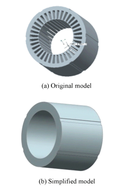
3 Calculation of Natural Frequency of Stator CoreStator core is composed of stator yoke and stator teeth. In order to simplify the analysis, the stator core is simplified into a cylindrical shell in the analytical calculation, as shown in Fig. 2. The physical parameters of the stator core are shown in Table 1.
|
Fig.2 Model of stator core |
3.1 Analytical Method for Natural Frequency of Stator Core
According to the Hoppe theory, the analytical formula for calculating natural frequencies of stator core is formula (1), and the calculated results are shown in Table 3.
| Table 3 Comparison of analytical and numerical results |
In Ref.[15], the length of the cylindrical shell has a small effect on its natural frequency. Therefore, the circumferential modal frequencies of cylindrical shell can be calculated by using formula of natural frequency of the infinite shell. In most mechanical engineering textbooks, the calculated formula for circumferential natural frequencies of the infinite shell is[16]:
| $ {f_m} = \frac{{{\mathit{\Omega }_m}}}{{{\rm{ \mathsf{ π} }}{D_t}}}\sqrt {\frac{{{E_t}}}{{{p_t}\left( {1 - v_t^2} \right)}}} $ | (3) |
where Dt is mean diameter of simplified model of stator core. Et, pt, vt, are respectively the elastic modulus, density and Poisson's ratio of simplified model of stator core. The physical parameters of the simplified model of stator core are the same as the stator yoke. On the basis of Donnel-Mushtari theory, the parameter Ωm, that is, the roots of the second order characteristic equation of motion are:
For circumferential mode m=0:
| $ {\mathit{\Omega }_0} = 1 $ | (4) |
For circumferential modes m≥1:
| $ \begin{array}{l} {\mathit{\Omega }_m} = \\ \;\;\;\;\frac{1}{2}\sqrt {\left( {1 + {m^2} + {k^2}{m^4}} \right) - \sqrt {{{\left( {1 + {m^2} + {k^2}{m^4}} \right)}^2} - 4{k^2}{m^6}} } \end{array} $ | (5) |
where the nondimensional thickness parameter
| $ {k^2} = \frac{{h_t^2}}{{3D_t^2}} $ | (6) |
where ht is thickness of simplified model of stator core. According to the Donnel-Mushtari theory, the calculated results are shown in Table 3.
3.2 Numerical Method for Natural Frequency of Stator CoreThe model used in the numerical method is still the actual model, that is, stator yoke and stator teeth. The model's density, elastic modulus and Poisson's ratio are shown in Table 1. The vibration mode shapes of circumferential modes m=2, 3, 4, 5 of numerical method are shown in Fig. 3 and the numerical results are shown in Table 3.

|
Fig.3 First four vibration mode (m=2, 3, 4, 5) shapes of stator core |
3.3 Comparison of Analytical and Numerical Results of Natural Frequency of Stator Core
As can be seen from Table 3, with the increase of the order of the circumferential modes, the relative errors between Hoppe theory and numerical method are more and more larger, but the relative errors between Donnel-Mushtari theory and numerical method are more and more smaller. In order to analyze the reasons, by comparing the changed rate of respective frequencies to investigate the varied trend of frequencies, the results of changed rate of frequencies of stator core are shown in Table 4.
| Table 4 Comparison of changed rate of circumferential modal frequencies of stator core |
As shown in Table 4, there is an approximately linear relationship between the changed rate of frequencies of Hoppe theory and that of numerical method. The differences between the changed rate of frequencies of Donnel-Mushtari theory and that of numerical method are from negative to positive, which make the relative errors between them fluctuate within a small range.
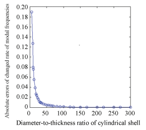
Through the above analysis, the changed trend of frequencies of Hoppe theory is more consistent with the actual situation. Therefore, the main reason which leads to the errors of changed rate of frequencies of Hoppe theory should be analyzed. Through the Ref.[15], diameter-to-thickness ratio has some influence on the natural frequency of cylindrical shell. From the Fig. 4 (ν represents diameter-to-thickness ratio), it shows that the changed rate of circumferential modal frequencies of cylindrical shell is an approximately linear relationship with the diameter-to-thickness ratio. The smaller the diameter-to-thickness ratio of cylindrical shell is, the lower the curve is. The higher the order is, the smaller the changed rate of frequencies is. Therefore, when the diameter-to-thickness ratio of cylindrical shell is smaller, the differences between the changed rate of frequencies calculated by Hoppe theory and that of numerical results are larger. The Hoppe theory is not suitable for the calculation of circumferential modal frequencies of cylindrical shell with the smaller diameter-to-thickness ratio. By changing the diameter-to-thickness ratio of the cylindrical shell, the absolute errors between the changed rate of frequencies of Hoppe theory and that of numerical method are shown in Fig. 5.

|
Fig.4 Changed rate of frequencies of circumferential modes of cylindrical shell with different diameter-to-thickness ratio |
|
Fig.5 Absolute errors between the changed rate of frequencies of Hoppe theory and that of numerical method of different diameter-to-thickness ratio of cylindrical shell |
As can be seen from Fig. 5, when the diameter-to-thickness ratio is greater than or equal to 120, the formula of Hoppe theory can be used. When the diameter-to-thickness ratio is less than 120, the diameter-to-thickness ratio should be taken into account in the formula of Hoppe theory. When the circumferential modal order m is 2, the calculated formula is the same as the formula(1). When the circumferential modal order m is greater than or equal to 3, the formula is:
| $ {f_m} = {f_2}{F_m} $ | (7) |
where f2 is the natural frequency when the circumferential modal order m is 2. Fm is the modal correction coefficient of each order when the circumferential modal order m is greater than or equal to 3.
| $ {F_m} = \prod\limits_{i = 2}^{m - 1} {\left( {{\varepsilon _i} - \Delta } \right)} $ | (8) |
where εi is the influenced coefficient of modal order.
| $ {\varepsilon _i} = \frac{{i + 2}}{{i - 1}}\sqrt {\frac{{{i^2} + 1}}{{{i^2} + 2i + 2}}} $ | (9) |
Δ is the influenced coefficient of diameter-to-thickness ratio, that is:
| $ \Delta = - 0.0473e - \frac{5}{{{v^3}}} + \frac{3}{{{v^2}}} - \frac{{0.048\;58}}{v} + 0.383\;8 $ | (10) |
where e is 2.718 28..., ν is the diameter-to-thickness ratio,
| $ v = \frac{{{D_t}}}{{{h_t}}} $ | (11) |
The circumferential modal frequencies of the stator core are calculated by the improved formula (7). The comparison between the results of analytical calculation using the improved formula and results of numerical method is shown in Table 5.
| Table 5 Comparing circumferential modal frequencies of stator core calculated by improved formula with them of numerical method |
As can be seen from Table 5, the results calculated by improved formula are significantly better than the results calculated by the Hoppe theory and Donnel-Mushtari theory.
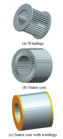
4 Calculation of Natural Frequency of Stator Core with WindingsIn the analytical calculation, the stator core is regarded as a cylindrical shell, and the windings in the slots are regarded as an additional ring internal to the stator core. The end windings are simplified as a hollow cylinder that is equivalent to the volume of the actual end windings.
In the numerical calculation, because of the complicated shape of actual end windings, it is difficult to build the model and produce the finite element mesh with good quality of model. In the establishment of the numerical model, a reasonable simplification of the windings is required. In this paper, the end windings are simplified as a hollow cylinder which is equivalent to the volume of the actual end windings.
The density of the windings in the slots is calculated according to the ratio of copper and epoxy resin. And the calculated methods of elastic modulus and Poisson's ratio refer to the Refs.[17-18]. The numerical model of stator core with windings is shown in Fig. 6, and the physical parameters are shown in Table 6.
|
Fig.6 Numerical model of stator core with windings |
| Table 6 Physical parameters of windings |
4.1 Analytical Method for Natural Frequency of Stator Core with Windings
According to the Ref.[13], the calculated formula of natural frequencies of stator core with windings is as follows:
| $ {f_m} = \frac{1}{{2{\rm{ \mathsf{ π} }}}}\sqrt {\frac{{K_m^t + K_m^d + K_m^n}}{{{M_t} + {M_d} + {M_n}}}} $ | (12) |
where Mt, Md, Mn are the quality of stator core, end windings and internal windings. Kmd, Kmn are the lumped stiffness of the end windings and internal windings. The calculated formula is as follows:
| $ K_m^d = \frac{{{m^2}\left( {{m^2} - 1} \right)}}{{{m^2} + 1}}\frac{{2{\rm{ \mathsf{ π} }}{E_d}{I_d}}}{{R_d^3}} $ | (13) |
where Rd is mean radius of the end windings. Id is area moment of inertia of the end windings, and the calculated method of Kmn is the same as the calculated method of Kmd.
Kmt is the lumped stiffness of the stator core.
1) For circumferential mode m=2:
| $ K_2^t = \frac{{115.2{\rm{ \mathsf{ π} }}{E_t}{I_t}}}{{D_t^3}} $ | (14) |
2) For circumferential modes m≥3,
| $ K_m^t = 4{{\rm{ \mathsf{ π} }}^2}f_2^2F_m^2{M_t} $ | (15) |
The analytical results calculated by formula (12) are shown in Table 7.
| Table 7 Comparing original analytical and improved analytical results with numerical results |
4.2 Numerical Method for Natural Frequency of Stator Core with Windings
The numerical model is imported into the ANSYS Workbench software, and the corresponding material attributes which are the same as the analytical method are attached to each part. The hexahedron is adopted to divide the mesh of the model. The model is divided into 40 662 elements. Finally, the free modal analysis is carried out. The vibration mode shapes of circumferential modes m=2, 3, 4, 5 of numerical method are shown in Fig. 7 and the numerical results are shown in Table 7.

|
Fig.7 First four vibration mode (m=2, 3, 4, 5) shapes of stator core with windings |
4.3 Comparison of Analytical and Numerical Results of Natural Frequency of Stator Core with Windings
From Table 7, the relative errors between analytical and numerical results are very large. The largest relative error between analytical and numerical results is |14.85%|. Therefore, the formula (12) should be corrected.
The reasons for the larger relative errors are that the simplification of the model and impregnating end windings make the stiffness of windings in the slots and end windings changed. Therefore, the stiffness in the formula (12) should be corrected. The improved formula is as follows:
| $ {f_m} = \frac{1}{{2{\rm{ \mathsf{ π} }}}}\sqrt {\frac{{K_m^t + {a_m}K_m^d + {b_m}K_m^n}}{{{M_t} + {M_d} + {M_n}}}} $ | (16) |
where am is the correction coefficient of stiffness of end windings, and
| $ {a_m} = 1.93m + 12.01 $ | (17) |
where bm is the correction coefficient of stiffness of windings in the slots, and
| $ {b_m} = - 53.302m + 111.51 $ | (18) |
According to the improved formula (16), the improved analytical results are shown in Table 7, and relative errors with the numerical results are also shown in Table 7. Now the relative errors between the analytical and numerical results are smaller.
5 Calculation of Natural Frequency of Motor CasingThe physical parameters of motor casing used in this paper are shown in Table 8.
| Table 8 Physical parameters of motor casing |
5.1 Analytical Method for Natural Frequency of Motor Casing
The formula of natural frequency of motor casing is as follows[13] :
| $ {f_m} = \frac{1}{{2{\rm{ \mathsf{ π} }}}}\sqrt {\frac{{K_m^f}}{{{M_f}}}} $ | (19) |
where Kmf and Mf are lumped stiffness and lumped mass of motor casing. The lumped stiffness for motor casing is:
| $ K_m^f = \frac{{4\mathit{\Omega }_m^2}}{{{D_f}}}\frac{{{\rm{ \mathsf{ π} }}{L_f}{h_f}{E_f}}}{{1 - v_f^2}} $ | (20) |
where Lf is effective length of motor casing, hf is thickness of the motor casing, Df is mean diameter of motor casing, the calculated method of the parameter Ωm is shown as the formulas (4) and (5).
According to the formula (19), natural frequencies of m=2, 3, 4, 5 of motor casing are calculated, and the results are shown in Table 9.
| Table 9 Comparing original analytical and improved analytical results with numerical results |
5.2 Numerical Method for Natural Frequency of Motor Casing
The physical parameters of the model which are used by the numerical method to calculate modes are the same as the analytical method. The vibration mode shapes of circumferential modes m=2, 3, 4, 5 of numerical method are shown in Fig. 8 and the numerical results are shown in Table 9.

|
Fig.8 First four vibration mode (m=2, 3, 4, 5) shapes of motor casing |
5.3 Comparison of Analytical and Numerical Results of Natural Frequency of Motor Casing
Comparison of the results of the analytical and numerical methods of circumferential modal frequencies of motor casing is shown in Table 9. The relative errors are larger, which are due to that one side of the model has a motor terminal box when it is considered in the numerical calculation, but it is not considered in the analytical calculation.
In order to make the analytical results more close to the numerical results, the formula (19) should be corrected. Because of the existence of motor terminal box, the stiffness of the motor casing is affected. The influence of the motor terminal box on the stiffness of the motor casing should be corrected, the improved formula is:
| $ {f_m} = \frac{1}{{2{\rm{ \mathsf{ π} }}}}\sqrt {\frac{{{c_m}K_m^f}}{{{M_f}}}} $ | (21) |
where cm is correction coefficient of stiffness of each order of motor casing
| $ {c_m} = 0.036\;7{m^3} - 0.41{m^2} + 1.513\;3m - 1.22 $ | (22) |
According to the improved formula (21), the improved analytical results are shown in Table 9, and relative errors with the numerical results are also shown in Table 9. Now the relative errors between the analytical and numerical results are smaller.
6 Calculation of Natural Frequency of Stator SystemThe stator system is composed of motor casing, stator core and windings. Its physical parameters are shown in Tables 1, 6 and 8.
6.1 Analytical Method for Natural Frequency of Stator SystemAccording to the Ref.[13], the expression for natural frequency of stator system is as follows:
| $ {f_m} = \frac{1}{{2{\rm{ \mathsf{ π} }}}}\sqrt {\frac{{K_m^t + K_m^n + K_m^d + K_m^f}}{{{M_t} + {M_n} + {M_d} + {M_f}}}} $ | (23) |
According to the formula (23), natural frequencies of m=2, 3, 4, 5 of stator system are calculated, and the results are shown in Table 10.
| Table 10 Comparing circumferential modal frequencies of stator system calculated by original and improved formulas with those of numerical and experimental methods |
6.2 Numerical Method for Natural Frequency of Stator System
In the numerical calculation, the contact between stator core and motor casing is set to be bonded. The vibration mode shapes of m=2, 3, 4, 5 of stator system obtained by the numerical method are shown in Fig. 9, and the results are shown in Table 10.

|
Fig.9 First four vibration mode (m=2, 3, 4, 5) shapes of stator system |
6.3 Comparison of Analytical and Numerical Results of Natural Frequency of Stator System
From Table 10, the relative errors between analytical and numerical results are very large. The largest relative error between analytical and numerical results is |22.61%|. Therefore, the formula (23) should be corrected.
Because of the influence of simplified model, impregnating end windings, motor terminal box on the motor casing and constraints on the stiffness of stator system, the relative errors between the analytical and numerical results are larger. The improved formula is as follows:
| $ {f_m} = \frac{1}{{2{\rm{ \mathsf{ π} }}}}\sqrt {\frac{{{k_m}\left( {K_m^t + {b_m}K_m^n + {a_m}K_m^d + {c_m}K_m^f} \right)}}{{{M_t} + {M_n} + {M_d} + {M_f}}}} $ | (24) |
where km is the correction coefficient of stiffness of stator system due to constrains in stator system
| $ {k_m} = - 0.076\;7{m^3} + 0.875{m^2} - 3.368\;3m + 4.96 $ | (25) |
According to the improved formula (24), the improved analytical results are shown in Table 10, and relative errors with the numerical results are also shown in Table 10. Now the relative errors between the analytical and numerical results are smaller.
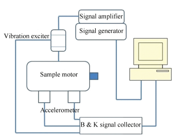
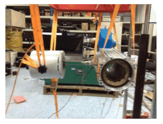
6.4 Modal Test of Vibration Exciter Method of Stator SystemIn order to verify the correctness of modal analysis of analytical method of stator system, the modal test software of vibration acoustic test system 7753 of Danish B & K Company is used to test modes of measured stator system through vibration exciter method. In order to make the restrained conditions of test consistent with them of the numerical method, the measured stator system which is hanged by elastic rope is tested.Fig. 10 shows the modal test sketch of sample motor. Fig. 11 is the photo of experimental site.
|
Fig.10 Modal test sketch of sample motor |
|
Fig.11 Photo of experimental site |
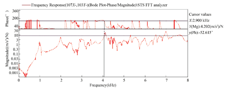
Firstly, the measured stator system is modeled in the B & K PULSE software, and the exciting points and test points are set up. In the stator system, the 81 measuring points are set up, the occurring signal is set as random signal, average vibration 100 times are as one step, and each step uses three acceleration transducers to record the signals of 3 testing points. Secondly, recorded 81 frequency response functions by accelerometers and the simplified model which is built in the PULSE software are imported into the post processing software of the B & K REFLEX[19-20]. Frequency response function of each measured point is summed, the natural frequency of each order of stator system is analyzed and valued. Phase function and frequency response function of some point are shown in Fig. 12. Fig. 13 is the vibration mode shapes of m=2, 3, 4, 5 by experimental test. The natural frequencies of the test are shown in Table 10.
|
Fig.12 Phase and frequency response functions of experimental mode of some point of stator system |

|
Fig.13 First four vibration mode (m=2, 3, 4, 5) shapes of stator system by experimental test |
7 Conclusions
In this paper, the following conclusions were obtained by studying the circumferential modal frequencies of the stator system:
(1) In the analytical calculation of natural frequencies of stator yoke, the relative errors between the calculated results of traditional analytical method (Hoppe theory) and the numerical results are in |7.04%|. Therefore, the analytical formula of natural frequency of stator yoke is not corrected.
(2) In the analytical calculation of natural frequencies of stator core, because of the smaller diameter-to-thickness ratio, calculated results of original analytical formula have larger errors. A novel analytical formula which considers diameter-to-thickness ratio is proposed. That makes the analytical results more close to the numerical results.
(3) In the analytical calculation of natural frequencies of stator core with windings, simplification of model and impregnating end windings make the stiffness of windings in the slots and end windings changed. These make the relative errors between analytical and numerical results larger. A novel formula of correcting the stiffness of end windings and internal windings is proposed. The relative errors between novel analytical and numerical results are in |4.59%|.
(4) In the analytical calculation of natural frequencies of motor casing, the motor terminal box on the one side of the model should be considered which affects the stiffness of motor casing. On the basis of the original formula, a correction coefficient of stiffness is added, which makes the relative errors between the novel analytical and numerical results in |0.56%|.
(5) In the analytical calculation of natural frequencies of stator system, the influence of simplified model, impregnating end windings, motor terminal box on the motor casing, constraints of model on the stiffness of stator system is considered comprehensively. A novel analytical method is proposed. Compared with the experimental and numerical results, the effectiveness of the novel analytical method is verified.
| [1] |
Bianchini C, Immovilli F, Lorenzani E, et al. Review of design solutions for internal permanent-magnet machines cogging torque reduction. IEEE Transactions on Magnetics, 2012, 48(10): 2685-2693. DOI:10.1109/TMAG.2012.2199509 (  0) 0) |
| [2] |
Tang Renyuan. Modern Permanent Magnet Machines: Theory and Design. Beijing: China Machine Press, 2016: 25-30. (in Chinese)
(  0) 0) |
| [3] |
Chen Yongxiao, Zhu Ziqiang, Ying Shancheng. Analysis and Control of Motor Noise. Hangzhou: Zhejiang University Press, 1987: 21-89. (in Chinese)
(  0) 0) |
| [4] |
Watanabe S, Kenjo S, Ide K, et al. Natural frequencies and vibration behavior of motor stators. IEEE Transactions on Power Apparatus & Systems, 1983, PER-3(4): 36. DOI:10.1109/MPER.1983.5519110 (  0) 0) |
| [5] |
Yu Y, Bi C, Jiang Q, et al. Prediction of vibration in PM synchronous motor based on calculation of stator natural frequency. Microsystem Technologies, 2015, 21(12): 2803-2810. DOI:10.1007/s00542-015-2589-1 (  0) 0) |
| [6] |
Wang Tianyu, Wang Fengxiang. Vibration and modal analysis of stator of large induction motors. Proceedings of the Chinese Society for Electrical Engineering, 2007, 27(12): 41-45. (in Chinese) DOI:10.3321/j.issn:0258-8013.2007.12.008.(inChinese) (  0) 0) |
| [7] |
Mori D, Ishikawa T. Force and vibration analysis of induction motors. IEEE Transactions on Magnetics, 2005, 41(5): 1948-1951. DOI:10.1109/TMAG.2005.846262 (  0) 0) |
| [8] |
Sterling H. Harmonic field effects in induction machines. Electronics & Power, 1977, 23(10): 841. DOI:10.1049/ep.1977.0457 (  0) 0) |
| [9] |
Timár P L, Fazekas A. Noise and Vibration of Electrical Machines. Amsterdam: Elsevier, 1989. (  0) 0) |
| [10] |
Yang S J. Low-Noise Electrical Motors. Oxford: Clarendon Press, 1981: 89-100.
(  0) 0) |
| [11] |
Hattori T, Narita K, Yamada T, et al. Modeling method of vibration analysis model for permanent magnet motor using finite element analysis. International Conference on Electrical Machines and Systems, 2009, 2009: 1-6. DOI:10.1109/ICEMS.2009.5382984 (  0) 0) |
| [12] |
Benbouzid M E H, Reyne G, Derou S, et al. Finite element modeling of a synchronous machine:Electromagnetic forces and modes shapes. IEEE Transactions on Magnetics, 1993, 29(2): 2014-2018. DOI:10.1109/20.250805 (  0) 0) |
| [13] |
Gieras J F, Wang C, Lai Joseph C S. Noise of Polyphase Electric Motors. Boca Raton: CRC Press, 2006: 110-116.
(  0) 0) |
| [14] |
Hoppe R. Vibrationen eines ringes in seiner ebene. Journal Für Die Reine Und Angewandte Mathematik, 1871(73): 158-170. DOI:10.1515/crll.1871.73.158 (  0) 0) |
| [15] |
Yu Shenbo, Wang Hui. Investigation of circumferential mode frequencies of circular cylindrical shells of stator in electric motor. Electric Machines and Control, 2014, 18(6): 102-107. (in Chinese) DOI:10.3969/j.issn.1007-449X.2014.06.017.(inChinese) (  0) 0) |
| [16] |
Leissa A W. Vibration of Shells. Melville, NY: American Institute of Physics, 1993.
(  0) 0) |
| [17] |
Witczak P, Brudny J F. Calculations of magnetic vibration forces in induction motors. Anesteziologiia Ⅰ Reanimatologiia, 1998, 57(6): 9-13. (  0) 0) |
| [18] |
Long S A. Vibration behavior of stators of switched reluctance motors. IEEE Proceedings-Electric Power Applications, 2001, 148(3): 257-264. DOI:10.1049/ip-epa:20010255 (  0) 0) |
| [19] |
Yu Shenbo, Wang Weiqi. Modal analysis of permanent magnet synchronous motorized spindle based on experimental and finite element method. Heavy Machinery, 2016(5): 68-71. (in Chinese) DOI:10.3969/j.issn.1001-196X.2016.05.014.(inChinese) (  0) 0) |
| [20] |
Dai Y, Cui S, Song L. Finite element method modal analysis of driving motor for electric vehicle. Proceedings of the Chinese Society for Electrical Engineering, 2011, 31(9): 100-104. (in Chinese) (  0) 0) |
 2019, Vol. 26


