2. Key Laboratory of Marine Environmental Monitoring and Information Processing, Ministry of Industry and Information Technology, Harbin 150001, China
In recent years, the inverse synthetic aperture radar (ISAR) technique has received much attention from the scholars around the world because of its value in military and civilian applications[1-6]. In particular, 3-D InISAR imaging algorithms have been extensively investigated because they can directly reflect the geometric information of the object, making it easier to identify the target. The basic idea of the algorithms is to use a special configuration of the multi-antenna to receive signals and obtain the 3-D geometry construction of the target by interferometric processing of the multiple two-dimensional (2-D) ISAR images after motion compensation and image coregistration[7-10]. Results in previous studies verified the effectiveness of the interference algorithm in 3-D imaging of non-cooperation targets with full aperture.
However, with the continuous enhancement of the radar system, modern radars usually need to have the collaboration capability of multifunction and multi-mode. In addition to achieving high-resolution imaging of the target, complicated tasks of wide-area exploration and multi-target tracking are also needed[11]. Therefore, radar systems are required to perform real-time alternation and switch between different functions, which will be extremely difficult for the broadband observation of the target with long-term and continuous data, making the echoes in gap missing sampling (GMS). Besides, there may be random missing sampling (RMS) of the echoes both in fast and slow times because of external or internal interference. When the echoes of the slow time domain are in these two types of sparse apertures and the signals of the fast time domain are in RMS, the results obtained by the traditional algorithms will have strong grating lobe and side lobe problems, which is a huge challenge for ISAR imaging and will bring lots of difficulties to the 3-D reconstruction of the target. Hence, it is necessary to study new 3-D InISAR imaging algorithms that are suitable for the target under such situations.
Traditional 3-D InISAR imaging algorithms with complete apertures can effectively achieve 3-D reconstruction of all kinds of targets[7, 9-13], but the reconstruction accuracy will decrease when there are some missing data or the received echoes are rare. Fortunately, with the development of the compressed sensing (CS) technology, it has become possible for the 3-D InISAR imaging of the target with sparse apertures[14-19]. Bayesian CS algorithm[15-16] and convex optimization method[17] were adopted to obtain 3-D InISAR images of the target through the signal reconstruction of the received small amount of continuous data. In Ref. [18], the motion-compensated one-dimensional (1-D) range profiles after random sampling and gap sampling were modeled as a joint sparse constraint optimization problem which was solved by combing the joint chirp-Fourier dictionary and the modified orthogonal matching pursuit (OMP) decomposition algorithm, then the 3-D geometry of the target was reconstructed by a joint estimation approach. The method in Ref. [19] regarded the reconstruction of the three 2-D images in sparse apertures as a problem of sparse reconstruction for the multiple measurement vectors, adopted the multiple sparse Bayesian learning algorithm to obtain the matched images, and then gained the 3-D reconstruction of the target. Although the previous studies on 3-D InISAR imaging with sparse apertures have achieved satisfying results, the problem of how to perform motion compensation for the sparse echoes received from the target which has translational and rotational components has not been considered and the sparsity in range dimension has not been discussed.
In this paper, a novel 3-D InISAR imaging algorithm for 2-D sparseness of ship targets with complicated movement is proposed. First of all, we discussed random missing in fast time domain, which is the problem of random sampling of the range dimension signals. Since the signal in range can be approximated as single frequency components, a large number of CS algorithms can be adopted to reconstruct the missing signals and achieve high-resolution of the range dimension. A phase-preserving Fourier basis and the OMP algorithm were combined to reconstruct the signals of the target with the sparsity in range dimension[20]. Similarly, we adopted the gradient adaptive algorithm with higher reconstruction accuracy[21] to recover three radar echoes which were sparse in range dimension. Then it is necessary to compensate the translational component of the echoes and the approach of minimizing the entropy of the average range profile[22-23] was used to realize the range alignment of the sparse echoes, which is different from the conventional motion compensation methods. Next, the joint phase autofocus method applying the improved minimum entropy was adopted to achieve the phase correction and image coregistration of the echoes at the same time after range alignment[24-25]. The method has many advantages under the circumstance of sparse aperture: 1) It has higher compensation accuracy compared with the eigenvector method, the Doppler center correction, and the constant phase difference elimination approach[26-28]; 2) Compared with the general minimum entropy phase correction method, this method is faster when the accuracy of the phase error is the same[29]; 3) Higher registration accuracy can be achieved for sparse apertures, and the error caused by the inaccurate estimation of the parameters in Ref. [30] can be reduced. Finally, combining the interferometric results of the 2-D ISAR images and the information of the range measurement, the 3-D geometry coordinates of the ship target with 2-D sparseness were constructed.
The overall structure of this paper is as follows. In Section 2, the algorithms for signal reconstruction, motion compensation, and image coregistration of the received echoes with 2-D sparsity are presented. The complete procedure of the proposed algorithm for the 3-D geometry reconstruction of the ship target is illustrated in Section 3. In Section 4, simulation experiments are carried out to verify the effectiveness and practicability of the proposed algorithm and the conclusions are drawn in Section 5.
2 Discussion of the 2-D Sparse Aperture EchoesThe 3-D InISAR imaging algorithm for maneuvering targets with full aperture is described in detail in Ref. [31]. According to Ref. [31], the 1-D range profiles of the three radars after motion compensation and image coregistration can be expressed as
| $ \begin{array}{*{20}{c}} {{s_K}\left( {r, {t_m}} \right) = \sum\limits_{p = 1}^P {{\sigma _p}} {\mathop{\rm sinc}\nolimits} \left( {{B_d}\left( {r - \frac{2}{c}\gamma {R_{op0}}} \right)} \right) \cdot }\\ {\exp \left( {{\rm{j}}{\varphi _{pK}}} \right)\exp \left( {{\rm{j}}\frac{{4\pi }}{c}{f_0}{{\tilde R}_{opk}}\left( {{t_m}} \right)} \right)} \end{array} $ | (1) |
where K stands for radars A, B, and C, p is the arbitrary scatterer of the target, and P is the total number of the scatterers. σp is the complex amplitude of the scatterer p, Bd is the bandwidth of the transmit signal, r is the radial distance, and Rop is the distance between scatterer p and the target's center o. φpK is the interference phase for 3-D InISAR imaging, f0 is the carrier frequency, and tm is the slow time. In a short coherent processing interval,
Different from 3-D InISAR imaging of the target with full aperture, it is required for echoes with 2-D sparsity to reconstruct the range dimension signal first, and then perform sparse motion compensation and image coregistration. The detailed theory will be introduced later.
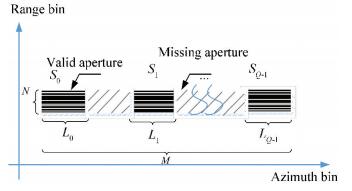
Fig. 1 and Fig. 2 show the two kinds of sparse samplings that are common in practice. As we all know, the number of the echoes in range depends on the sampling frequency and the pulse width, so there will be no continuous missing of the signals under normal circumstances. Therefore, we consider the RMS in range dimension reasonable in this paper. It is assumed in Fig. 1 and Fig. 2 that the echoes in range dimension are missing at the same sampling time in order to make it more convenient for drawing, which is almost impossible to occur in practice. Therefore, the simulation in this paper considers the range dimension to lose data at different sampling times. However, the azimuth echo data is different from the range which only considers random loss of the data in that on the one hand the random missing of the echoes makes the data incomplete during the imaging time, but on the other, multifunctional radars only assign a specific imaging time period for ISAR imaging, and the periodical scan causes the discontinuous reception of the echo data segment. These two types are both considered in the azimuth dimension of the echoes in this paper as shown in Fig. 1 and Fig. 2.

|
Fig.1 Echoes in 2-D RMS |
|
Fig.2 RMS in range dimension and GMS in azimuth dimension |
The previous research shows that when the received echoes are incomplete, they will bring difficulties to the 2-D ISAR imaging of the target, and the accuracy of the motion compensation and image coregistration in 3-D InISAR imaging of the target will be decreased correspondingly. Therefore, it will be discussed in the following parts on how to perform high-precision 3-D reconstruction of ship targets with 2-D sparse echoes.
2.1 Signal Reconstruction of the Range DimensionIt can be seen in Eq. (1) that the target's echo signal of the range dimension can be approximated as a superposition of the multiple single-frequency signals. Although the echoes are not complete due to the RMS of the range, a large number of CS algorithms such as OMP and SL0 can achieve high-precision reconstruction of the missing data. In this paper, we choose the gradient descent method which has high reconstruction accuracy for random missing signal to reconstruct the range dimensional signal of the target.
It is assumed that the discrete of the echoes can be expressed as sK (m, n), m=0, 1, …, M-1, n=0, 1, …, N-1, M is the total number of the echoes, and N is the number of the range bin. The vector matrix of the echoes is expressed as
| $ \begin{array}{c}{\boldsymbol{s}_{r K}=\left[\boldsymbol{s}_{K 0}^{\mathrm{T}}, \boldsymbol{s}_{\mathrm{K} 1}^{\mathrm{T}}, \cdots, \boldsymbol{s}_{K(M-1)}^{\mathrm{T}}\right]} \\ {\boldsymbol{s}_{K_{m}}=\left[s_{K}(m, 0), s_{K}(m, 1), \cdots, s_{K}(m, N-1)\right]}\end{array} $ | (2) |
Use sKm(n), n=0, 1, …, N-1 to substitute sKm, suppose that only ns(ns < N) random data can be obtained, mark the position of these data as ni∈NA={n1, n2, …, ns}, and correspondingly, the position of the missing data is NQ=CNNA. The sparse echoes of sKm(n) are represented as sKmSA(n)=sKm(n), n∈NA, and the values of the signals in position n∈NQ are zero. Since the signal sKm is sparse in the Fourier domain, the signal reconstruction is converted to the following optimization problem[21]
| $ \min \left\|X_{K m}\right\|_{1}, s_{K m}^{S A}(n)=s_{K m}(n), n \in N_{A} $ | (3) |
where
| $ X_{K m}(k)=\mathrm{FFT}\left(s_{K_{m}}^{S A}(n)\right), k=0, 1, \cdots, N-1 $ |
In order to obtain the minimum value of ||XKm||1, the calculation of the missing sample (variable) values can be defined by using the gradient descent on the sparsity measure of ||XKm||1. According to Ref. [21], the gradient vector of ||XKm||1 is
| $ g\left(n_{i}\right)=\frac{\left\|X_{K m}^{+}\right\|_{1}-\left\|X_{K m}^{-}\right\|_{1}}{2 N \triangle}, n_{i} \in N_{Q} $ | (4) |
| $ X^{+}_{K m}(k)=\operatorname{FFT}\left(s_{K m}^{S A}(n)+\triangle \delta\left(n-n_{i}\right)\right) $ | (5) |
| $ X^{-}_{K m}(k)=\mathrm{FFT}\left(s_{K m}^{S A}(n)-\triangle \delta\left(n-n_{i}\right)\right) $ | (6) |
where
| $ s_{K m}^{S A 1}(n)=s_{K m}^{S A}(n)-\alpha g(n) $ | (7) |
where the step α=2△. Then the new signal
1) Given the number of the iterations J, the iteration step
2) Start iteration, l=1;
3) YY1=YY2=srKSA, if n∈NSA, do the calculation:
| $ \begin{array}{c}{Y_{1}(m, k)=\operatorname{FFT}\left(s_{r K}^{S A}\left(m, n_{x}\right)+\triangle(m)\right)} \\ {Y_{2}(m, k)=\operatorname{FFT}\left(s_{r K}^{S A}\left(m, n_{x}\right)-\triangle(m)\right)}\end{array} $ |
and the gradient of the mth signal at n is
| $ G_{r}\left(m, n_{x}\right)=\frac{1}{2 N \triangle(m)} \sum\limits_{k=0}^{N-1}\left(Y_{1}(m, k)-Y_{2}(m, k)\right) $ |
4) If n∈CN NSA, Gr (m, nx) =0;
5) Update the signal
srKSA(m, n)=srKSA(m, n)-α(m)Gr(m, n), l=l+1
6) If l>J, stop the iteration and the reconstructed signal matrix is sK=srKSA. Otherwise, return to 3) to continue the iteration.
After we obtain the reconstructed echoes sA, sB, and sC of radars A, B, and C, the next step is to perform the motion compensation for them.
2.2 Envelope Alignment of the Sparse Aperture EchoesMotion compensation is a necessity for obtaining ISAR images after the high-precision reconstruction of the RMS echoes in range dimension. Envelope alignment is the first step, and the coherence of the echoes is reduced due to the missing sampling, especially for the non-continuous aperture as shown in Fig. 2. Traditional methods of compensation such as the accumulation of cross-correlation and minimum entropy[32-33] are not applicable. It has been verified that the global minimum entropy method which uses the value of the average range profile entropy as the basis of the range alignment to realize envelope alignment can achieve effective convergence even though the received data is extremely incomplete[22-23].
It is assumed that the 1-D range profiles fASA, fBSA, and fCSA of radars A, B, and C can be obtained by the range compression of the reconstruction signals sA, sB, and sC, respectively. The average range profile of radar A is thus expressed as
| $ {f_{{\rm{ }}A{\rm{ave }}}}(\Delta \mathit{\boldsymbol{r}}, r) = \sum\limits_{m = 0}^{M - 1} {f_A^{SA}} (m, r + \Delta r(m)) $ | (8) |
where r is defined as the range, and
| $ \triangle \boldsymbol{r}=[\triangle r(0), \cdots, \Delta r(M-1)] $ |
is the distance vector which is employed to shift the range profile of the other pulse to coincide with the first pulse. The Shannon entropy of fAave(△r, r) is calculated as
| $ \begin{array}{l}{E(\triangle \boldsymbol{r})=} \\ {-\sum\limits_{m=0}^{M-1} \frac{f_{A\text { are }}(\triangle r(m), r)}{F} \ln \frac{f_{\text { Aare }}(\triangle r(m), r)}{F}}\end{array} $ | (9) |
where
| $ E(\Delta \boldsymbol{r})=-\sum\limits_{m=0}^{M-1} f_{\mathrm{Aave}}(\Delta r(m), r) \ln f_{\mathrm{Aave}}(\triangle r(m), r) $ |
in which minimizing E(△r) means to seek the vector △r when
| $ \left.\frac{\partial\left[f_{A}^{S A}(m, r) \oplus \ln \left(f_{\text { Aave }}(m, -r)\right)\right]}{\partial r}\right|_{r=\Delta r(m)}=0 $ | (10) |
where ⊕ represents convolution. The solution of Eq. (10) is △r when fASA(m, r)⊕ln (fAave(-r)) obtains the maximum value. Using △r to shift all the pulses of radar A, the average range entropy which will decrease until the envelope is aligned can be updated correspondingly. The steps of the envelope alignment algorithm are as follows:
1) Given the initial range vector △r=0, the 1-D range profile is fASA(m, r), and calculate the average range profile
2) The Shannon entropy is
| $ E=-\sum\limits_{r=0}^{N-1} f_{\text { Aave }}(r) \ln \left(f_{\text { Aave }}(r)\right) $ |
3) Find the maximum value of fASA(m, r)⊕ln (fAave(-r)); Use fast Fourier transform to find △r since the convolution is difficult to achieve. Then
| $ \begin{aligned} \Delta \boldsymbol{r}(m)=& \max\limits_{r=0, 1, \cdots, N-1} \operatorname{IFFT}\left(\left(\operatorname{FFT}\left(f_{A}^{S A}(m, r)\right)\right)^{*}\right.\cdot \\ & \operatorname{FFT}\left(\ln \left(f_{\text { Aave }}(-r)\right)\right) \end{aligned} $ |
4) Update fAave(r) by using Eq. (8), and then update the Shannon entropy E;
5) If E is reduced, return to 3) to continue the iteration, otherwise, stop the iteration and get the final value of △r.
In 3-D InISAR imaging, the range alignment of each radar is determined by the parameters of the center antenna A, and △r is used to compensate all echoes. The compensated 1-D range profiles of radars A, B, and C can be obtained as follows:
| $ \left\{\begin{array}{l}{f_{A 1}^{S A}(m, r)=f_{A}^{S A}(m, r+\triangle r(m))} \\ {f_{B 1}^{S A}(m, r)=f_{B}^{S A}(m, r+\Delta r(m))} \\ {f_{C 1}^{S A}(m, r)=f_{C}^{S A}(m, r+r(m))}\end{array}\right. $ | (11) |
There are still some phase errors after the envelope alignment including range-aligned residuals and the portions caused by the missing data, which will prevent the echoes from ISAR imaging. Therefore, it is essential to eliminate the phase error. In order to reduce the amount of computation and improve the accuracy of phase correction, useless echoes of fK1SA are removed and valid echoes are retained. The matrix of the valid data is expressed as fK1(m, r), m=0, 1, …, Ms, where Ms is the length of the valid echoes as shown in Fig. 2, and Ms=L0+…+LQ-1. Then the algorithms proposed in Refs. [24-25] can all be used for phase correction.
After motion compensation, the wave path differences of the three radars will cause the three ISAR images to mismatch so that the interference cannot be achieved and the 3-D InISAR image of the target cannot be obtained. The algorithm in Ref. [30] needs to estimate parameters first which will then be used to achieve the image coregistration. This algorithm works well when the echo is complete. While in this paper, the discontinuity of the echoes makes the parameter estimation not applicable. A new method based on the joint phase autofocus to achieve phase correction and image coregistration at the same time is proposed in Ref. [24], which is very effective for sparse aperture echoes because it is based on the fast global minimum entropy criterion. The phase correction and ISAR imaging of the echoes can be expressed as
| $ \begin{array}{*{20}{l}} {{g_{K1}}(k, r) = }\\ {\quad \sum\limits_{m = 0}^{{M_s} - 1} {{f_{K1}}} (m, r)\exp \left( {{\rm{j}}{\varphi _K}(m)} \right)\exp \left( { - {\rm{j}}\frac{{2\pi }}{{{M_s}}}km} \right)} \end{array} $ | (12) |
where k is the discrete frequency, φK(m) is the adjustment phase, and gK1(k, r) is the complex image. It can be seen in Eq. (12) that the main problem for ISAR imaging is the estimation of φK(m). φK(m) is designed to minimize the entropy of |gK1(k, r)| since entropy can be used to measure the focus quality of the ISAR images. The entropy is defined as
| $ {E_1} = - \sum\limits_{k = 0}^{{M_s} - 1} {\sum\limits_{r = 0}^{N - 1} {\frac{{\left| {{g_{K1}}(k, r)} \right|}}{S}} } \ln \frac{{\left| {{g_{K1}}(k, r)} \right|}}{S} $ | (13) |
where
| $ {E_1} = - \sum\limits_{k = 0}^{{M_s} - 1} {\sum\limits_{r = 0}^{N - 1} {\left| {{g_{K1}}(k, r)} \right|} } \ln \left| {{g_{K1}}(k, r)} \right| $ | (14) |
When Eq. (14) takes the minimum, ∂E1/∂φK(m)=0. From Ref. [25], we have
| $ \frac{{\partial {E_1}}}{{\partial {\varphi _K}(m)}} = 2{M_s}{\mathop{\rm Im}\nolimits} \left\{ {\exp \left( {{\rm{j}}{\varphi _K}(m)} \right){a_K}(m)} \right\} = 0 $ | (15) |
where
| $ \begin{array}{*{20}{c}} {{a_K}(m) = \sum\limits_{r = 0}^{N - 1} {{f_{K1}}} (m, r)(\sum\limits_{k = 0}^{{M_s} - 1} {\ln } \left| {{g_{K1}}(k, r)} \right| \cdot }\\ {{g^*}_{K1}(k, r)\exp ( - {\rm{j}}\frac{{2\pi }}{M_s}km))} \end{array} $ | (16) |
Finally, the phase error can be obtained by
| $ \varphi_{K}(m)=-\operatorname{angle}\left(a_{K}(m)\right) $ | (17) |
In order to get a high quality ISAR image, φK(m) is obtained through iteration. The algorithm steps are as follows:
1) Initialize the phase error φK(m)=0, m=0, 1, …, Ms;
2) Obtain the ISAR image
| $ g_{K 1}(k, r)=\operatorname{FFT}\left(f_{K 1}(m, r) \exp \left(\mathrm{j} \varphi_{K}(m)\right)\right) $ |
3) Calculate
| $ {a_K}(m) = \sum\limits_{r = 0}^{N - 1} {{f_{K1}}} (m, r){\mathop{\rm FFT}\nolimits} \left( {\ln \left| {{g_{K1}}(k, r)} \right|g_A^*(k, r)} \right) $ |
4) Update φK(m)=-angle(aK(m));
5) Decide whether φK(m) meets the precision requirement. If it is satisfied, the iteration stops; otherwise, return to 2) to continue the iteration.
When K=B, C, the ISAR image gA(k, r) of radar A is obtained after the joint phase adjustment. Finally, the images after coregistration can be obtained and the 3-D geometry reconstruction of the ship target with 2-D sparse aperture can be achieved by using the three ISAR images gA(k, r), gB(k, r), and gC(k, r)[31].
3 3-D InISAR Imaging Procedure of the TargetThe 3-D InISAR imaging algorithm of ship targets with 2-D sparse apertures proposed in this paper mainly includes the following sections: 1) Conduct signal reconstruction of the sparse echoes received from radars A, B, and C in range dimensionl; 2) Use the global minimum entropy of the average range profile method to eliminate the translational components of the echoes; 3) Apply the joint phase adjustment approach to obtain the registered ISAR images of the three radars; 4) Interfere the three ISAR images and combine the range measurement to reconstruct the 3-D coordinates of the target. The technological procedure of the algorithm is illustrated in Fig. 3.

|
Fig.3 Flow chart of the 3-D InISAR imaging algorithm of the ship target |
4 Simulation Results 4.1 The Target Model and Parameter Setting
In this section, a series of simulation experiments are presented to verify the effectiveness of the proposed algorithm for 3-D InISAR imaging of the ship target with 2-D sparseness. The 3-D ideal model of the ship target is given in Fig. 4, where Fig. 4(a) is the position of the scatterers in ξ- η plane, Fig. 4(b) is the position of the scatterers in η-ζ plane, Fig. 4(c) is the position of the scatterers in ξ-ζ plane, and Fig. 4(d) is the position of the scatterers in ξ-η-ζ. Table 1 shows the parameters of the radar system, and the distance between radar A and the center of the ship target at the time t=0 is 8 km. The ship target has complex motion parameters, and Table 2 lists the 3-D rotation parameters of the target in detail. In addition to rotation, the ship target has translation velocity in UOV plane, where vU=38.6 knots and vV=10.4 knots.

|
Fig.4 3-D ideal model of the ship target |
| Table 1 Parameters of the simulation radar system |
| Table 2 3-D rotation parameters of the ship target |
4.2 Simulation Experiments
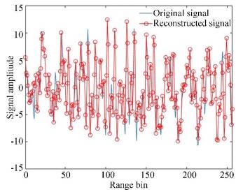
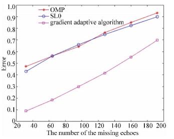
Experiment 1: Reconstruct the echoes in range dimension. When the echoes are randomly missing in the range dimension, it will affect the accuracy of motion compensation, image coregistration, and interference imaging. In order to obtain a more accurate 3-D InISAR image, the missing signal should be reconstructed in the first place. There are lots of CS algorithms such as OMP and SL0, which can be used to restore the original signal with less data. Since the gradient adaptive algorithm is particularly effective for the recovery of the echoes with random missing sampling, it is chosen to reconstruct the echoes which are missing in range dimension. Taking the 33rd echo of radar A as an example, suppose that there are 64 data losses. Fig. 5 shows the comparison between the original signal and reconstructed signal, in which the two signals were almost the same. The reconstruction errors of different CS algorithms are given in Fig. 6, which shows that as the number of the missing echoes increased, the signal reconstruction errors increased gradually. But the errors of the gradient adaptive algorithm were always smaller than that of the other two CS algorithms.
|
Fig.5 Comparison of the original signal and the reconstructed signal |
|
Fig.6 Reconstruction error comparison of different algorithms |
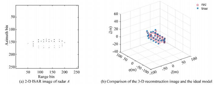
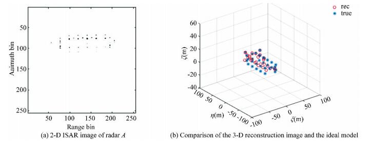
Experiment 2: Discuss 3-D InISAR imaging of the ship target with 2-D random missing sampling. It is supposed that there are 64 data random losses in each range unit at different sampling time, the total number of the echoes are 512. The results in Figs. 7-9 show the 2-D ISAR images and 3-D InISAR images of the ship target under different sparse apertures. Fig. 7 gives the results of the target when the echoes are 3/4 sparse aperture, which means the random missing number of the echoes are 128. The 2-D ISAR image of radar A in 3/4 sparse aperture is shown in Fig. 7(a), in which all scatterers were well separated and concentrated in the imaging plane. The ISAR images of radars B and C after image coregistration are not presented in this paper since they are the same as radar A except that they carry the interference phase of the ship target which are used for 3-D reconstruction. Fig. 7(b) gives the 3-D InISAR image of the ship target after the interference processing of the three images. It can be seen that all the coordinates of the scatterers were reconstructed, and the position of the reconstructed scatterers coincided exactly with the true scatterers. The imaging results of the target with 2/4 sparse aperture are shown in Fig. 8, in which the 2-D ISAR image in Fig. 8(a) was in good quality even though it was a little worse than that of Fig. 7(a). Although the reconstruction coordinates of some scatterers in Fig. 8(b) were not as accurate as that in Fig. 7(b), the scatterers were still completely reconstructed. In Fig. 9, the echoes are 1/4 sparse aperture and the missing data are 384. It can be found that the general contour of the target was still available although the results of the 2-D ISAR image in Fig. 9(a) and the 3-D InISAR image in Fig. 9(b) were not as good as those in Fig. 7 and Fig. 8. Therefore, we can draw the conclusions as follows: 1) The accuracy of the 3-D reconstruction coordinates will decrease with the increase of the missing echoes; 2) The 3-D InISAR imaging results are almost the same as the real target when the missing echoes are controlled within a certain range, and the approximate contour of the target can be obtained even when the missing echoes are absent.

|
Fig.7 Echoes with 3/4 sparse aperture |
|
Fig.8 Echoes with 2/4 sparse aperture |
|
Fig.9 Echoes with 1/4 sparse aperture |
Experiment 3: Discuss 3-D InISAR imaging of the ship target with random missing in range dimension and gap missing in azimuth dimension. We assumed that the randomly missing data is 64 in each range unit at the same time, and the received effective echo is 256. Suppose that there are 64 echoes in each aperture, a total of 4 apertures are used for imaging. Fig. 10 shows the 1-D range profile of radar A with the effective echoes accounts for 1/4 of the received echoes, which is an example of GMS.

|
Fig.10 1-D range profile of the effective echoes accounts for 1/4 of the received echoes |
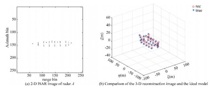
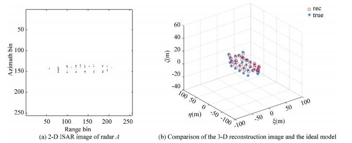
The total number of the echoes in Fig. 11, Fig. 12, and Fig. 13 are 512, 1024, and 2048, respectively. In these figures, (a) shows the 2-D ISAR image of radar A and (b) is the comparison between the 3-D reconstruction of the ship target and the ideal model. Obviously, the quality of the results in (a) and (b) is influenced by the interval between effective apertures that the effect of the images gets worse when the interval increases. However, the 3-D geometry coordinates of the target with the effective echoes accounting for 1/8 of the received echoes were still well reconstructed, which confirms that the algorithm proposed in this paper is appropriate for GMS echoes.
|
Fig.11 Effective echoes accounts for 1/2 of the received echoes |
|
Fig.12 Effective echoes accounts for 1/4 of the received echoes |

|
Fig.13 Effective echoes accounts for 1/8 of the received echoes |
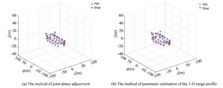
Experiment 4: Discuss 3-D InISAR imaging of the target by adopting different methods of image coregistration. The number of the missing data in range dimension is the same as that of Experiment 3. Fig. 14 and Fig. 15 present the results of the 3-D reconstruction of the ship target by adopting different image coregistration algorithms, where (a) shows the image of using joint phase autofocus and (b) indicates the method of parameter estimation of the 1-D range profile. According to Fig. 14(a) and Fig. 15(a), all the scatterers on the target were reconstructed with high precision and it is clear that the coordinates of the 3-D InISAR image almost exactly corresponded with the real model because the global joint phase adjustment algorithm is appropriate to phase correction and image coregistration when the echoes are in sparse aperture. The algorithm of image coregistration based on the parameter estimation of the 1-D range profile were not accurate enough in the absence of the echoes so that most scatterers could not be reconstructed accurately as shown in Fig. 14(b) and Fig. 15(b).

|
Fig.14 3-D InISAR imaging of ship by using different image coregistration algorithm with randomly missing 2/4 sparse aperture of the 512 echoes |
|
Fig.15 3-D InISAR imaging of ship by using different image coregistration algorithms with gap missing and the effective echoes accounts for 1/4 of the received echoes |
5 Conclusions
A novel 3-D InISAR imaging algorithm for ship targets is proposed in this paper to deal with the problem which is difficult for traditional 3-D InISAR imaging methods when the received echoes are in 2-D sparseness. The gradient adaptive algorithm was adopted to reconstruct the signals in range dimension, and the method of minimizing the entropy of the average range profile was applied to achieve the range alignment of the reconstructed echoes. The phase adjustment and the image coregistration of the three radars were completed at the same time by using the joint phase autofocus approach. We finally obtained the 3-D geometry coordinates of the ship target with 2-D sparsity after interfering the three registered images. The simulation results show that the proposed algorithm can effectively achieve 3-D InISAR imaging of the ship target both in RMS and GMS. Although the quality of the 3-D image decreases with the increase of the missing data, the contour of the target can be obtained even if the echoes are random missing 3/4 sparse aperture. Besides, the complete information of the 3-D geometry coordinates of the ship target can be obtained when the received echoes are in large aperture intervals.
| [1] |
Zheng J B, Su T, Zhu W T, et al. ISAR imaging of targets with complex motions based on the keystone time-chirp rate distribution. IEEE Geoscience and Remote Sensing Letters, 2014, 11(7): 1275-1279. DOI:10.1109/LGRS.2013.2291992 (  0) 0) |
| [2] |
Zheng J B, Su T, Zhang L, et al. ISAR imaging of targets with complex motion based on the chirp rate-quadratic chirp rate distribution. IEEE Transactions on Geoscience and Remote Sensing, 2014, 52(11): 7276-7289. DOI:10.1109/TGRS.2014.2310474 (  0) 0) |
| [3] |
Bai X, Tao R, Wang Z J, et al. ISAR imaging of a ship target based on parameter estimation of multicomponent quadratic frequency-modulated signals. IEEE Transactions on Geoscience and Remote Sensing, 2014, 52(2): 1418-1429. DOI:10.1109/TGRS.2013.2251348 (  0) 0) |
| [4] |
Thayaparan T, Lampropoulos G, Wong S K, et al. Application of adaptive joint time-frequency algorithm for focusing distorted ISAR images from simulated and measured radar data. IEE Proceedings-Radar, Sonar and Navigation, 2003, 150(4): 213-220. DOI:10.1049/ip-rsn:20030670 (  0) 0) |
| [5] |
Li G, Zhang H, Wang X Q, et al. ISAR 2-D imaging of uniformly rotating targets via matching pursuit. IEEE Transactions on Aerospace and Electronic Systems, 2012, 48(2): 1838-1846. DOI:10.1109/TAES.2012.6178106 (  0) 0) |
| [6] |
Rao W, Li G, Wang X Q, et al. Adaptive sparse recovery by parametric weighted L1 minimization for ISAR imaging of uniformly rotating targets. IEEE Journal of Selected Topics in Applied Earth Observations and Remote Sensing, 2013, 6(2): 942-952. DOI:10.1109/JSTARS.2012.2215915 (  0) 0) |
| [7] |
Qiu W, Martorella M, Zhou J, et al. Three-dimensional inverse synthetic aperture radar imaging based on compressive sensing. IET Radar, Sonar and Navigation, 2015, 9(4): 411-420. DOI:10.1049/iet-rsn.2014.0260 (  0) 0) |
| [8] |
Liu Y, Song M, Wu K, et al. High-quality 3-D InISAR imaging of maneuvering target based on a combined processing approach. IEEE Geoscience and Remote Sensing Letters, 2013, 10(5): 1036-1040. DOI:10.1109/LGRS.2012.2227935 (  0) 0) |
| [9] |
Ng B, Tran H T, Phan A. Total rotational velocity estimation using 3D interferometric ISAR with squint geometry. Proceedings of 2016 IEEE Radar Conference (RadarConf). Piscataway: IEEE, 2016.1-6. DOI: 10.1109/RADAR.2016.7485206.
(  0) 0) |
| [10] |
Martorella M, Stagliano D, Salvetti F, et al. 3D interferometric ISAR imaging of noncooperative targets. IEEE Transactions on Aerospace and Electronic Systems, 2014, 50(4): 3102-3114. DOI:10.1109/TAES.2014.130210 (  0) 0) |
| [11] |
Nasirian M, Bastani M H. A novel model for three-dimensional imaging using interferometric ISAR in any curved target flight path. IEEE Transactions on Geoscience and Remote Sensing, 2014, 52(6): 3236-3245. DOI:10.1109/TGRS.2013.2271875 (  0) 0) |
| [12] |
Xu X, Narayanan R M. Three-dimensional interferometric ISAR imaging for target scattering diagnosis and modeling. IEEE Transactions on Image Processing, 2001, 10(7): 1094-1102. DOI:10.1109/83.931103 (  0) 0) |
| [13] |
Lv Q, Su T, Zheng J, et al. Three-dimensional interferometric inverse synthetic aperture radar imaging of maneuvering target based on the joint cross modified Wigner-Ville distribution. Journal of Applied Remote Sensing, 2016, 10(1): 015007. DOI:10.1117/1.JRS.10.015007 (  0) 0) |
| [14] |
Bacci A, Staglianó D, Giusti E, et al. 3D interferometric ISAR via compressive sensing. Proceedings of 2014 11th European Radar Conference. Piscataway: IEEE, 2014. 233-236. DOI: 10.1109/EuRAD.2014.6991250.
(  0) 0) |
| [15] |
Liu Y, Li N, Wang R, et al. Achieving high-quality three-dimensional InISAR imageries of maneuvering target via super-resolution ISAR imaging by exploiting sparseness. IEEE Geoscience and Remote Sensing Letters, 2013, 11(4): 828-832. DOI:10.1109/LGRS.2013.2279402 (  0) 0) |
| [16] |
Wang Y, Li X. Three-dimensional interferometric ISAR imaging for the ship target under the bi-static configuration. IEEE Journal of Selected Topics in Applied Earth Observations and Remote Sensing, 2016, 9(4): 1505-1520. DOI:10.1109/JSTARS.2015.2513774 (  0) 0) |
| [17] |
Chen Q, Xu G, Zhang L, et al. Three-dimensional interferometric inverse synthetic aperture radar imaging with limited pulses by exploiting joint sparsity. IET Radar, Sonar and Navigation, 2015, 9(6): 692-701. DOI:10.1049/iet-rsn.2014.0275 (  0) 0) |
| [18] |
Xu G, Xing M, Xia X G, et al. 3D geometry and motion estimations of maneuvering targets for interferometric ISAR with sparse aperture. IEEE Transactions on Image Processing, 2016, 25(5): 2005-2020. DOI:10.1109/TIP.2016.2535362 (  0) 0) |
| [19] |
Zhang S, Liu Y, Li X. Sparse aperture InISAR imaging via sequential multiple sparse Bayesian learning. Sensors, 2017, 17(10): 2295. DOI:10.3390/s17102295 (  0) 0) |
| [20] |
Zhang S, Zhang W, Zong Z, et al. High-resolution bistatic ISAR imaging based on two-dimensional compressed sensing. IEEE Transactions on Antennas and Propagation, 2015, 63(5): 2098-2111. DOI:10.1109/TAP.2015.2408337 (  0) 0) |
| [21] |
Stanković L, Daković M. On a gradient-based algorithm for sparse signal reconstruction in the signal/measurements domain. Mathematical Problems in Engineering, 2016.Article ID 6212674. DOI: 10.1155/2016/6212674.
(  0) 0) |
| [22] |
Zhu D, Wang L, Yu Y, et al. Robust ISAR range alignment via minimizing the entropy of the average range profile. IEEE Geoscience and Remote Sensing Letters, 2009, 6(2): 204-208. DOI:10.1109/LGRS.2008.2010562 (  0) 0) |
| [23] |
Zhu D, Li Y, Yu X, et al. Compressed ISAR autofocusing: Experimental results. Proceedings of the 2012 IEEE Radar Conference. Piscataway: IEEE, Proceedings of the 2012. 425-430. DOI: 10.1109/RADAR.2012.6212178.
(  0) 0) |
| [24] |
Wu W, Hu P, Xu S, et al. Image registration for InISAR based on joint translational motion compensation. IET Radar Sonar and Navigation, 2017, 11(10): 1597-1603. DOI:10.1049/iet-rsn.2017.0140 (  0) 0) |
| [25] |
Qiu X H. Fast minimum entropy phase compensation for ISAR imaging. Journal of Electronics and Information Technology, 2004, 26(10): 1656-1660. (  0) 0) |
| [26] |
Zhang L, Duan J, Qiao Z J, et al. Phase adjustment and ISAR imaging of maneuvering targets with sparse apertures. IEEE Transactions on Aerospace and Electronic Systems, 2014, 50(3): 1955-1973. DOI:10.1109/TAES.2013.130115 (  0) 0) |
| [27] |
Lv X, Xing M, Wan C, et al. ISAR imaging of maneuvering targets based on the range centroid Doppler technique. IEEE Transactions on Image Processing, 2010, 19(1): 141-153. DOI:10.1109/TIP.2009.2032892 (  0) 0) |
| [28] |
Qiu X, Zhao Y, Cheng A H W, et al. Phase compensation in ISAR imaging: Comparison between maximum likelihood-based approach and minimum entropy-based approach. IEEE Antennas and Propagation Society International Symposium, 2004. Piscataway: IEEE, 2004. 2107-2110. DOI: 10.1109/APS.2004.1330625.
(  0) 0) |
| [29] |
Wang J, Liu X, Zhou Z. Minimum-entropy phase adjustment for ISAR. IEE Proceedings-Radar, Sonar and Navigation, 2004, 151(4): 203-209. DOI:10.1049/ip-rsn:20040692 (  0) 0) |
| [30] |
Zhang Q, Yeo T S, Du G, et al. Estimation of three-dimensional motion parameters in interferometric ISAR imaging. IEEE Transactions on Geoscience and Remote Sensing, 2004, 42(2): 292-300. DOI:10.1109/TGRS.2003.815669 (  0) 0) |
| [31] |
Wang Y, Chen X. 3-D Interferometric inverse synthetic aperture radar imaging of ship target with complex motion. IEEE Transactions on Geoscience and Remote Sensing, 2018, 56(7): 3693-3708. DOI:10.1109/TGRS.2018.2806888 (  0) 0) |
| [32] |
Liu J, Feng Y, Li H, et al. Supercontinuum pulse measurement by molecular alignment based cross-correlation frequency resolved optical gating. Optics Express, 2011, 19(1): 40-46. DOI:10.1364/OE.19.000040 (  0) 0) |
| [33] |
Wang G, Bao Z. The minimum entropy criterion of range alignment in ISAR motion compensation. Radar Systems(Radar 97). London: IET, 1997. 236-239.DOI: 10.1049/cp:19971669.
(  0) 0) |
 2019, Vol. 26


